multicarrier modulation and Reed Solomon Coding to obtain system that has excellent .... In this work a Matlab simulation program for an OFDM system with RS error correction capability ..... [10]Ye (Geoffrey) Li and Gordon L. Stiiber.
Journal of Engineering and Development, Vol. 16, No.3, Sep. 2012 ISSN 1813- 7822
Reed Solomon Coding in Orthogonal Frequency Division Multiplexing (OFDM) Communication Systems Dr. Kadhum Al-Majdi,
Dr. Raed Saleem Al-Moussawy
Laith Anwer Hasan
Department of Electrical Engineering AL-Mustansriaya University, Baghdad-IRAQ
Department of Electrical Engineering Kufa University, Najaf-IRAQ
AL-Mustansriaya University, Baghdad-IRAQ
Abstract: This paper presents a MATLAB simulation that has been developed to investigate Orthogonal Frequency Division Multiplexing (OFDM) communication system using Reed Solomon (RS) Coding process. The efficient encoding and decoding algorithm, and the powerful of error correction capability of Reed Solomon Coding make it one of the most widely used error correction codes algorithm, so we use it with OFDM systems to merge the benefits of multicarrier modulation and Reed Solomon Coding to obtain system that has excellent performance capability in multipath and fading channels. Single-carrier QAM and multicarrier OFDM are compared to demonstrate the strength of OFDM in multipath channels. The bit error rate and the number of error bits are calculated during each test on the system. Two simulations of OFDM are developed with inter modulation QPSK or 16-QAM with Reed Solomon Coding are using to correct errors of transmitted data. Keywords: Multicarrier OFDM, Reed Solomon Coding, Single-carrier QAM, Multipath and Fading channels.
الترميز بتقنية ريد سلمون في أنظمة االتصاالت المتعامدة التردد بالتقسيم :الخالصة والتي تمم تطويرهما لتحقيم نظمام االتصماالت المتعاممد التمردد بالتقسميمMATLAB تعرض هذه الورقة المحاكاة باستخدام برنامج عملية الترميمز وفم الترميمز الوءمووة والقمدرة القويمة لمعالصمة وتصمحي. (RS) (باستخدام تقنية الترميز ريد سلمونOFDM) لمذل تمم اسمتخدامع مم, ) جعلها واحدة من اكثر التقنيات المستخدمة بصورة واسعة لتصحي الخطأRS( الخطأ لتقنية ريد سلمون )RS( ) وتقنيممة الترميممز ريممد سمملمونmulticarrier modulation( ) لممدمج فوا ممد الت مممين متعممدد النواق مOFDM( أنظمممة 162
Journal of Engineering and Development, Vol. 16, No.3, Sep. 2012 ISSN 1813- 7822
) وقنموات التشيميmultipath channels ( لغرض الحصول على نظمام يمتلم قمدرة ممتماالة االداو فمي القنموات متعمددة المسمار ) لتوضمي قموة نظمامQAM( ) ونظمام الناقم الواحمدOFDM( اي ا تتم المقارنة بين نظام متعدد النواقم.)fading channels( ) Bit Error Rate ( حيم تمم حسماس نسملة الخطمأ. ) multipath channels (متعمدد النواقم فمي القنموات المتعمددة المسمار )OFDM( واخيمرا تمم تطموير محاكماتين لنظمام متعمدد النواقم. ) في ك اختلار اجري على النظامError Bits ( وعدد االخطاو ) وتمم اسمتخدام16-QAM( ) واالخر م الت مين الداخلي باستخدام النظامQPSK( احدهما م الت مين الداخلي باستخدام النظام . ) في كلتا المحاكاتين لتصحي االخطاو الحاصلة في الليانات المرسلةRS( تقنية الترميز ريد سلمون
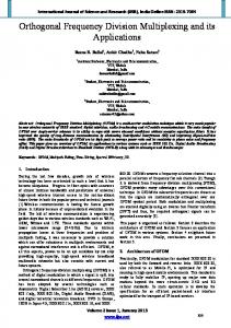
1. Introduction With the rapid growth of digital communication in recent years, the need for high-speed data transmission has increased. New multicarrier modulation techniques such as Orthogonal Frequency Division Multiplexing are currently being implemented to keep up with the demand for more communication capacity. Multicarrier communication systems “were first conceived and implemented in the 1960s, but it was not spread until the FFT is discovered by Cooly and Tukey at the beginning of the computer resolution [1] , so OFDM became feasible and economical [2- 4]. Two of the fundamental advantages of OFDM are its robustness against channel dispersion and its ease of phase and channel estimation in a time-varying environment [5]. A common problem found in high-speed communication is inter-symbol interference (ISI). ISI occurs when a transmission interferes with itself and the receiver cannot decode the transmission correctly. Because the signal reflects from large objects such as mountains or high buildings, the receiver sees more than one copy of the signal. In communication terminology, this is called multipath. Since the indirect paths take more time to travel to the receiver, the delayed copies of the signal interfere with respect to the direct signal, causing ISI. As communication systems increase their information transfer speed, the time for each transmission necessarily becomes shorter. Since the delay time caused by Multipath remains constant, ISI becomes limited in high-data-rate communication [6]. OFDM avoids this problem by sending many low speed transmissions simultaneously. High data rates can be achieved in OFDM by transmitting a number of orthogonal subcarriers [7]. So OFDM is especially suitable for high-speed communication due to its resistance to ISI. The second problem is fading channel, where the delayed reflected signals added to the main signal and cause either gains in the signal strength or deep fades. For deep fades case, the signal is nearly wiped out. The signal level is very small, therefore; the receiver cannot decide what was there. One of the main reasons of using OFDM is to increase robustness against frequency-selective fading or narrowband interference [8]. OFDM signal offers advantage for the channel that has a frequency selective fading response. As shown in figure (1), when an OFDM signal spectrum is lying against the frequency- selective response of the channel, only two sub-carriers are affected, while the remaining others are not [9]. OFDM has been
163
Journal of Engineering and Development, Vol. 16, No.3, Sep. 2012 ISSN 1813- 7822 proved to be an effective technique to combat multipath fading in wireless channels [10]. Besides its implementational flexibility, the low complexity required in transmission and reception as well as the attainable high performance render OFDM a highly attractive candidate for high-datarate communications over time-varying frequency-selective radio channels [11]. Coding in OFDM systems are able to achieve excellent performance on frequency selective channels because of the combined benefits of multicarrier modulation and coding [12, 13]. Reed Solomon or RS codes are the most well-known and the most widely-used codes having non-binary symbols [14]. Reed Solomon (RS) coding process has the ability to correct random errors, as well as many random bursts of errors, for this reason RS Codes are popular in many practical systems [15]. In this work a Matlab simulation program for an OFDM system with RS error correction capability have been developed and implemented. This paper is organized as follows. The description of the system blocks are detailed in section 2. Simulation results are discussed in section 3 and the final section gives conclusions.
Figure(1). Spectrum of OFDM signal against the response of channel.[9]
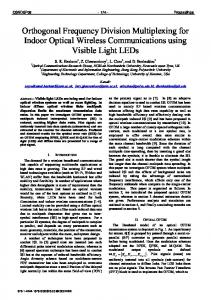
2. System Description The block diagram in figure (2) illustrates a general block diagram for the proposed simulation model. In the input data block, the data are converted to a binary representation. We can see that the data pass through RSEncoding. Then, it pass through modulation process. In the modulation block, we can choose the inter-modulation type for OFDM (QPSK or 16-QAM) and compare it with16-QAM. After that, the modulated data will pass through the channel. Then, the received modulated data will pass through demodulation and RS Decoding. Finally, the received data are converted to the original form in the output data block.
164
Journal of Engineering and Development, Vol. 16, No.3, Sep. 2012 ISSN 1813- 7822
Transmitter Input data
RS encoding
Modulation
Channel
Output data
RS decoding
Demodulation
Receiver
Figure(2)General Simulation block diagram The details of each block are illustrated in the following.
2.1 Input and Output Data Blocks The input data block can accept three different types of input: binary random data, text, and audio. The output format of this block is binary. So for the text data, the ASCII code of each character is taken and converted to 8-bit binary data string. For the audio data, at first the audio waves are converted to samples, the range level of these samples is between -1and +1. Then, the sample’s level is normalized to be a real number between 0 and 255. After that, it is converted to 8 bit-binary data. In the output data block, the same operations of the input data block are applied on the received data but in reverse order, this means the received data are converted back to the original form.
2.2 Reed Solomon Encoding and Decoding Blocks Figure 3 shows the RS block diagram of the procedure of encoding and decoding data. First in the RS encoder block, the input data is converted to symbols (each m binary data converted to a decimal symbol). This symbols is converted to a number of parallel messages (message length = s) knowing that, before this procedure zeros must be padded to generate an integer number of messages if necessary. Then the data encoded (messages become codes). After that the parallel codes are converted to serial codes. These codes are passed through a modulator (modulation procedure), channel and demodulator (demodulation process). In the RS decoder block, the procedure that has been applied on the received codes will be opposite to that in the RS encoder block.
165
Journal of Engineering and Development, Vol. 16, No.3, Sep. 2012 ISSN 1813- 7822
Input data
Convert binary data to symbol (symbol length=m)
Convert binary data to symbols
Serial symbols To parallel codes (cods length=N)
Serial symbols To parallel Msgs (Msg length=s)
Parallel msgs to serial symbol
Parallel codes to serial symbols
Convert symbols to binary data
modulation
channel
Demodulation
decode codes
Encode Msgs
Convert symbols to binary data
Output data
Figure(3)Reed Solomon block diagram
2.3 Modulation and Demodulation Blocks In the modulation block, the inter-modulation type for OFDM as either QPSK or 16-QAM can be chosen. The operation in the demodulation block will be opposite to that in the modulation block. The construction of the modulation and demodulation blocks for each system will be illustrated in the following paragraphs.
2.3.1 OFDM Block The block diagram in figure (4) shows the OFDM configuration. In all types of modulation the input binary data (0,1) is converted to polar form (-1,1). Inter-modulation type (QPSK or 16-QAM) is chosen as described before. The input data are converted from serial to parallel (chunks) where chunks length = number of carrier. In our simulation program 32 carriers are used, FFT size =128. Also a number of zeros are padded in between, so that chunk length will be compatible with FFT size. After the channel, the operation in the demodulation block will be opposite to that in the modulation block. In our simulation program the BER in percentage is computed.
Input data
RS encoding
QPSK or QAM Mod.
Serial to Parallel
IFFT
Parallel to Serial
Channel
Output data
RS decoding
QPSK or QAM Demod.
Parallel to Serial
Figure(4)OFDM detailed block diagram 166
FFT
serial to parallel
Journal of Engineering and Development, Vol. 16, No.3, Sep. 2012 ISSN 1813- 7822
2.3.2 16- QAM Block The block diagram in figure (5) shows the 16-QAM configuration. The input binary data are converted from binary form to polar form. Then the polar form data are converted to four levels data form (-1, 1,-3, 3). After that, the data are converted into two types, in phase (I) and quadrature phase (Q). The in phase data are multiplied by cosine and quadrature are multiplied by sine. Both of them are summed together and then are transmitted .The previous procedures are reversed in blocks followed channel block, the received data are changed (may increases or decreases) because channel’s effects, so using make decision between (-1,1,-3,3) will be accomplished. Then the BER will be calculated. Quadrature phase
RS encoding
Inputdata
Binary to polar(1,1)
Polar to 4 level converter (-1,-3,1,3)
shift by 90
Serial to parallel(I,Q )
∑ LO
Inphase
Channel Quadrature phase
Output data
RS decoding
Polar (1,-1) to binary
Make decision between (-1,-3,1,3)
4 level to Polar converter (1,-1)
shift by 90
Parallel to serial
LO
Inphase
Figure (5) 16-QAM block diagram
2.3.3 Channel Block In the proposed simulation program, multipath channel with Additive White Gaussian Noise (AWGN) is used. Knowing that, the channel can be turned ON or turned OFF. Also, the SNR of different values for testing the system in different situation are applied. The block diagram in figure (6) shows the channel configurations.
167
Journal of Engineering and Development, Vol. 16, No.3, Sep. 2012 ISSN 1813- 7822
Multipath
Mod. Data in
AWGN
Mod. Data out
Figure(6) Channel block diagram
3. Simulation Results The OFDM with QPSK inter modulation system and OFDM with 16-QAM inter modulation system versus 16-QAM system with different input data types and different channel types are extensively tested. The bit error rate and the number of error bits during each test are calculated. In some tests, we used Reed Solomon Coding with the systems to correct errors and reduce the bit error rate as demonstrated in table bellow :Table(1) Simulation results
OFDM with (7,3)
Channel Type
Reed
of input data
Solomon
Random
Multipath
AWGN
channel
channel
ON
OFF
ON
coding
QPSK inter-modulation
OFDM with 16-QAM Inter-
16-QAM
modulation
BER
Bit
BER
Bit
BER
Bit
%
errors
%
errors
%
errors
OFF
0
0
9.63
1577
22.1
3615
ON
OFF
1
164
14
2301
23.6
3859
ON
ON
OFF
0.993
17
12.7
217
22.4
383
ON
ON
ON
0
0
9.75
167
20.1
344
ON
ON
OFF
1.07
1812
12.3
20807
20.2
34316
ON
ON
ON
0.00707
12
8.77
14877
19.8
33659
binary data(214 bit) Text
Audio
168
Journal of Engineering and Development, Vol. 16, No.3, Sep. 2012 ISSN 1813- 7822
The Original Data
OFDM with QPSK
OFDM with 16-QAM
inter-modulation transmission
Inter-modulation transmission
BER = 0.993%
BER = 12.7%
Bit Errors = 17
Bit Errors = 217
16-QAM transmission BER = 22.4% Bit Errors = 383
OFDM is a combination of
OGDM is a
KFD`is`p` czlb_na´ij^$jV$
O_E^$¹rT ±d£__bYm!´yo^
modulation and multiplexing.
comcination#ofmodulatinn and
m•`ulat-_o0Q~d mylyepm`