Int J Adv Manuf Technol DOI 10.1007/s00170-010-2571-0
ORIGINAL ARTICLE
Retrieval of CAD model data based on Web Services for collaborative product development in a distributed environment Byung Chul Kim & Duhwan Mun & Soonhung Han
Received: 1 November 2009 / Accepted: 4 February 2010 # Springer-Verlag London Limited 2010
Abstract Web Services, a distributed component technology based on XML and the Internet, is used for integrating heterogeneous systems under a distributed environment. Since CAD data is used as master data across the lifecycle of a product, it is important to share CAD data efficiently among the systems that are used for collaborative product development in a distributed environment. In this study, the concept of Web Services for CAD (WSC), which provides CAD data when required by organizations participating in the collaborative product development, is introduced. In addition, the technical details of WSC, including the system architecture of WSC, XML-based neutral CAD model, and interface for retrieving CAD model data are discussed. Finally, the implementation of WSC to Pro/ENGINEER and its experimental result are explained. Keywords CAD data retrieval . Collaborative product development . Service-oriented architecture . Web services B. C. Kim Institute of Industrial Technology, Samsung Heavy Industries Co., Ltd., 103-28 Munji-dong, Yuseong-gu, Daejeon 305-380, South Korea e-mail:
[email protected] D. Mun (*) Marine Safety & Pollution Response Research Department, Maritime & Ocean Engineering Research Institute, KORDI, 171 Jang-dong, Yuseong-gu, Daejeon 305-343, Republic of Korea e-mail:
[email protected] S. Han Department of Mechanical Engineering, Korea Advanced Institute of Science and Technology, 373-1 Gusong-dong, Yuseong-gu, Daejeon 305-701, South Korea e-mail:
[email protected]
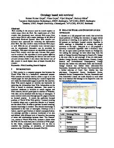
1 Introduction Today's companies strive to survive in a competitive global environment by providing customers with high-quality products at low prices in a timely manner. As one of these efforts, companies, moving away from the traditional method in which all the product development activities are carried out by one company, are attempting to introduce a collaborative product development method in which a company concentrates only on its core activity and collaborates with other companies for other activities. In other words, collaborative product development in a distributed environment is a new product development process in which multidisciplinary stakeholders participates in the design decision making and share product data across enterprise boundaries in an Internet-enabled distributed environment [1]. In collaborative product development in a distributed environment, the participating companies, which are geographically distributed and have different cultures, are assigned their tasks according to a predefined product development process; these companies perform their tasks and share the results of their tasks with other participating companies in order to develop the product (see Fig. 1). From the viewpoint of engineering systems, an integration of the engineering systems that are used by the participating companies is required for sharing product data after the development process for a product is defined and the companies that are responsible for activities consisting of the process are decided. The integration of the engineering systems for collaborative product development is affected by the level of data exchange and the collaborative relationship among participating companies. &
Level of data exchange: The participating companies are responsible for the activities of designing the sub-
Int J Adv Manuf Technol Fig. 1 System integration for collaborative product development in a distributed environment
&
assemblies or parts that make up a product or other activities such as analysis, testing, and manufacturing. In order to perform these activities, the data equal or above the part level is shared among participating companies through a variety of forms such as boundary representation (B-rep) models and parametric models. Collaborative relationship: The collaborative relationship among participating companies is not permanent; it changes according to the interest of the companies that participate in the collaborative projects. The companies that are in cooperation may also be in competition, depending on the projects. Therefore, it is essential to provide only the minimum data that are required for the collaboration and to block access to all unnecessary data or the internal system of the company.
The fact that the collaborative relationship may change according to projects or with time also implies that integration of engineering systems should be carried out independently of each company's internal systems. In this regard, the integration of the systems for collaborative product development should be loosely coupled. Loosely coupled integration enables data sharing among the systems on the basis of the definition of the standardized interface, data format, and protocol. Furthermore, it reduces the interdependence among the systems. In loosely coupled integration, the interface is developed in such a way that the dependency between the systems is minimum and the change in other systems caused by a change in an application system or a module is minimized. Collaborative product development based on loosely coupled integration is not always a solution. The automotive
industry or the aerospace industry sometimes constructs a product development environment that is based on tightly coupled and homogeneous CAX (CAD/CAM/CAE) systems and PLM (Product Lifecycle Management) systems. However, as can be seen in the case of the iPod development by Apple Inc. [2], there is no gainsaying that product development is also trending toward concentrating on what a company does best and establishing flexible partnerships with other companies for developing products collaboratively. The distributed object technologies such as CORBA [3], COM [4], JavaRMI, and Web Services [5] are adequate for loosely integrating the various application systems used in a collaborative product development environment. Among them, Web Services can resolve the limitations that the previous distributed object technologies, such as CORBA and COM had; can represent service-oriented Architecture (SOA) well; and has the advantage that it is a framework based on XML and the Internet. Because Web Services is an adequate technology to share product lifecycle data, including CAD data, manufacturing data, process planning data, and resource management data among participating companies on a network, it has been used in recent studies in the engineering domain [1, 6–10]. The application systems used in product development are classified into two categories: (1) systems that generate product data such as CAD, CAM, and CAE and (2) systems that manage product data and development processes like PLM. Similarly, Web Services in a distributed product development environment can be divided into the Web Services that carries out engineering activities and Web Services that is responsible for change management, versioning, data management, and so on. In addition, it is necessary to
Int J Adv Manuf Technol
establish a process or a mechanism to integrate these Web Services. Business Process Execution Language (BPEL) [11] is the representative language for such integration. BPEL is an OASIS standard executable language for specifying executable business processes and abstract business processes. Because the CAD data generated in a design phase are used in the next stages of the product lifecycle as master data, the data sharing between CAD systems or between a CAD system and other downstream applications is required. Previous studies on Web Services in engineering environments usually focused on CAD modeling [1], real-time collaborative design [6–8], and the control and composition of Web Services [9, 10]. However, studies on Web Services that provide the data designed by using a CAD system to other Web Services in the format they require have been unsatisfactory. Basically, CAD data can be considered to contain the design information and knowledge of products. Based on CAD data, various types of knowledge on products and their related processes are accumulated and evolved during the product lifecycle. In order to completely exploit product and process knowledge that is normally known implicitly to the separate designers, it must be made explicit and shared among designers across the enterprise [12]. Regarding knowledge management and reuse, various studies on knowledge management and integration platforms for a design process [12], knowledge-based conceptual design [13], ontology-based assembly information representation and sharing [14], and reference design knowledge retrieval technology [15] have been performed. This paper proposes Web Services for CAD (WSC) as a framework for sharing CAD models using Web Services. In particular, we have focused on essential technological elements required for implementing Web Services, which provides CAD data, the system architecture, the XML-based neutral CAD model for representing CAD data, and the interface definition for interaction between systems. The remainder of this paper is organized as follows: Section 2 describes previous work regarding the integration of engineering systems. Section 3 introduces the concept of WSC and explains the technical details. Section 4 discusses the implementation of WSC for Pro/ ENGINEER and experiments with test CAD models. Section 5 presents the conclusions and directions for future works. Table 1 CAD data exchange and CAD data sharing [16]
2 Review of related literature and studies 2.1 CAD data exchange and sharing When software systems participate in a product design process, they obtain CAD model data in two ways. The first of these is via CAD data exchanges; the second is by CAD data sharing [16]. CAD data exchange utilizes a data file for the exchange of CAD models; in contrast, CAD data sharing usually uses an application programming interface (API) to access CAD model data. A comparison of these two methods is shown in Table 1. CAD data exchange generally uses standard formats for the exchange of CAD models. Among them, representative standard formats are ISO 10303 [17], which is known as the Standard for the Exchange of Product Model Data (STEP) as published by the International Organization for Standardization (ISO) and the Initial Graphics Exchange Specification, which is the national standard of the United States. Standard CAD model data is exchanged in a text format. While the text format has a larger file size and slower process time than a binary format, it can be easily interpreted by a computer as well as by a human. In addition, it is not dependent on an operating system or a hardware platform. The pioneering studies on CAD model exchange have focused on the exchange of a B-rep model [18], which consists of topological and geometric data. Since the early 2000s, exchange of parametric models that include features, design constraints, and design history has been studied [19– 22]. Recently, studies [23, 24] that attempt to represent the semantics contained in CAD models and thus, to increase the range and accuracy of the data, exchange using ontology have been conducted. However, there has been no study that has suggested a rigid solution to the important issues in the exchange of CAD models, such as persistent naming [25], feature mapping [26], and the tolerance problem. The concept of CAD data sharing is to share CAD model data using the API provided by a CAD system. However, an API is usually oriented to or customized for a specific CAD system; thus, it is difficult to use it for the purpose of data sharing with other CAD systems. In order to resolve this problem, standard CAD APIs such as the Application Interface Specification (AIS) [27], ISO 13584-31 [28], Djinn [29], and OMG CAD Services [30] have been proposed. In particular, OMG CAD Services is the standard interface
CAD data exchange
CAD data sharing
Initiated by data originator Transformed into a neutral format Content determined by discrete event in time Redundant copy of data created
Initiated by data receiver Use of API of data originator Data on demand in real-time Appears as single data source
Int J Adv Manuf Technol
specification used to share CAD model data between a CAE system and a CAD system in a distributed environment using CORBA technology. Standard interfaces for CAD sharing, like OMG CAD Services, are realized by using the API provided by a CAD system. However, since the data types of the input and output arguments that are used in the standard interfaces are different from those in a CAD system API, data translation is required in the realization process. This implies that the CAD data sharing also has the data loss problem, the same as the CAD data exchange. 2.2 Distributed object technology The traditional approach for sharing CAD models in a distributed environment is to use a distributed object technology, such as CORBA, COM, or Java RMI, as the basis for implementing the distributed data sharing functionality [31–33]. The role of the distributed object technology is to enable the applications to call on the services of distributed software components (objects) in a transparent manner, hiding the details of the underlying networks, platforms, and implementation languages. Coupled with an interface that provides standard access to data repositories, distributed object technology can provide transparent access to remote data, without the need for building a different interface for each application, storage system, network, and operating system in the integrated environment. However, the use of distributed object technologies presents several disadvantages, which were pointed out in [34]. Distributed object technologies have been developed to support the frequent exchange of small amounts of data. However, in collaborative product development, the partlevel data is sequentially exchanged among systems according to the product development process that is addressed in Section 1. This fact requires an asynchronous type of communication and the exchange of large volumes of data. In addition, implementing CORBA or COM on the basis of distributed environments over wide-area networks, such as the Internet, is a challenging task as CORBA and COM traffic finds it difficult to pass through firewalls; they are also platform-dependent. 2.3 Web Services As an alternative to using distributed object technologies, Web Services, which is based on XML and the Internet, has emerged. Web Services comprises a number of standard recommendations, but the most basic recommendations among these are Web Services Description Language (WSDL) [35], which enables a service provider to describe the interface of the service, and Simple Object Access Protocol (SOAP) [36], which is a protocol to let applica-
tions exchange data over the Internet. Essentially, a WSDL document and a SOAP document are XML documents as they are written in XML. WSDL is a language that describes the interface of Web Services. A service requester of Web Services can identify the function that Web Services provides using a WSDL document. WSDL has a similar role to that of interface description language (IDL), which is used to describe the interface of CORBA, and Microsoft IDL (MIDL), which is used to describe the interface of COM. A WSDL document usually contains the protocol binding for interacting with Web Services, the interface specification, the data structure, the port type, and the message types written in XML. The data structure implies the structure of the data exchanged between a service provider and a service requester, and it is defined by XML Schema [37]. A SOAP document describes the protocol used for exchanging a message over a computer network. SOAP enables Web Services to exchange an XML document that contains the input and output of the Web Services. The XML message, which has a structure that is based on XML tags, contains the input and output data of Web Services. The Web Services platforms such as AXIS and .NET Framework can automatically generate the class definitions in a specific language from the XML Schema defined in a WSDL document. Using these classes, a developer can implement Web Services. The SOAP message is marshaled or unmarshaled in order to bind to the instance of the class. As a result, a service provider or a service requester can use Web Services using the syntax of its development language. In addition, there is Universal Description, Discovery, and Integration (UDDI) [38], which is the W3C recommendation regarding how to register Web Services on a public registry that a service provider wants to deploy and how to search the Web Services that a service requester wants to use. There is also a DISCO file, which specifies the location of the WSDL document that a Web server provides. The use of XML and its related technologies in a distributed environment can overcome the aforementioned problems arising from the use of distributed object technologies, which is shown in Table 2. Web Services is more suited to the asynchronous mode of communication and the exchange of large volumes of data. In addition, XML traffic could easily pass through firewalls and is more platform-independent because SOAP can use HTTP as its underlying transfer protocol even though SOAP can use several transfer protocols. However, most importantly, XML and its related technologies provide a plethora of tools that are easily available [34]. Comparison with similar studies is shown in Table 3. The study that is most similar to the current one is OMG CAD Service [30], which provides CAD data in a distributed environment using CORBA. Other similar studies are those
Int J Adv Manuf Technol Table 2 Comparison of distributed object technologies and Web Services
Distributed object technologies
Web Services
Better at synchronous communication Better at frequent exchange of small amounts of data Difficult to pass through firewalls Platform-dependent
Better at asynchronous communication Better at exchange of large volumes of data Easily pass through firewalls Platform-independent
conducted by Wang et al. [1] and Chen et al. [8]. Wang et al. [1] proposed document-driven design approach using Web Services, and Chen et al. [8] developed Web Services for the exchange of procedural CAD models. & 3 Web Services for CAD
&
3.1 Basic concept
&
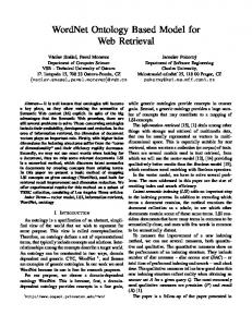
The tasks assigned to companies participating in a collaborative product development project include the design of sub-assemblies or parts, analysis, manufacturing, and testing. Because participating companies in each product development project vary from project to project, the systems operated by the companies should be integrated in a loosely coupled form. WSC, which is proposed in this study in the context of collaborative product development in a distributed environment, is defined as “Web Services that provide CAD model data that is used as underlying data during the product lifecycle by processing and converting it into the form that a service requester requires in order to support the integration of the systems operated by the companies participating in the collaborative product development in a distributed environment”. A service requester such as a CAD system and a PDM system calls the WSC function and then obtains the necessary CAD model data from WSC using the interface defined by the WSDL document of WSC. The procedure is as follows and is shown in Fig. 2. &
Generally, a service requester searches the necessary Web Services using UDDI. However, because in
& &
&
collaborative product development, the participating companies know the endpoint of the Web Services that the companies want to use, UDDI is not necessary in this situation. A service requester requests the WSDL document that specifies the WSC interface to WSC (Fig. 2-1). WSC returns the WSDL document to the service requester (Fig. 2-2). The service requester asks WSC to send a CAD file to the service requester by calling “the operation for CAD model data retrieval” defined by the WSDL document (Fig. 2-3). WSC extracts the necessary data from the proprietary CAD file using CAD API (Fig. 2-4). WSC transforms the data to the XML format corresponding to the predefined XML-based neutral CAD model and then returns it to the service requester (Fig. 2-5). The service requester transforms the XML-based CAD data received from WSC to the format that the service requester needs. Then, the service requester uses the data for its purpose. This paper does not mention the post-processing that transforms the XML-based CAD data to other formats.
Technological features of WSC are multilayered system architecture, XML-based neutral CAD model, and WSDL that will be separately elaborated in Sections 3.2, 3.3, and 3.4. 1. Multilayered system architecture Servicing CAD data to downstream applications requires reading, processing, and providing CAD data in various forms suitable to downstream applications. In this study, the XML-based neutral CAD model and neutral API are
Table 3 Comparison with similar studies
Distributed object technology Interface type Multilayered architecture Support of various input and output data types/formats
This study
OMG CAD Services [30]
Chen et al. [8]
Wang et al. [1]
Web Services Data-centric O O
CORBA Method-centric N/Aa X
Web Services Method-centric X
Web Services Data-centric X O
△b
a
Because OMG CAD Services only provide interface specifications, the system architecture is not mentioned
b
It supports only the exchange of procedural CAD models
Int J Adv Manuf Technol Fig. 2 Use of Web Services for CAD
WSC : Service Requester
1 : Request WSDL() WSDL
2 : WSDL
3 : Retrieve CAD model data()
4 : Extract CAD model data using API()
5 : XML document
defined at the Web Service layer of WSC. The neutral API is implemented in the CAD adapter layer below the Web Service layer with the use of the native API of commercial CAD systems. This architecture enables the Web Services to have extensibility and reusability. 2. XML-based neutral CAD model Web Services for CAD data service should have a capability of providing various types of information that applications require. For example, in order to support collaborative design, CAD systems require all information contained in original CAD data while the downstream applications such as CAE, CAPP, and CAM systems usually require geometric data. The XML-based neutral CAD model defined in this study can represent not only geometric data but also parametric information. It also can represent both CAD part data and CAD assembly data. In addition, the Web Services should convert CAD data to forms that other applications need. The implementation of such transformations can be easily achieved without any structural change in WSC, which is attributed to the multilayered architecture of WSC. 3. Data-centric interfaces While OMG CAD service defined method-centric interfaces, this study proposes the concept of data-centric interfaces and applies it so as to define the interfaces of WSC (Web Services for CAD). Method-centric interfaces that have complex hierarchical structures are used in order to retrieve simple data. During the retrieval process, simple and small amounts of data are repeatedly exchanged. Method-centric interfaces are of advantage to synchronous communication as they need a tightly coupled relationship. In contrast, data-centric interfaces are simple interfaces with simple structures to retrieve complex hierarchical data. This data, irrespective of its complexity, can be retrieved in
a single transaction. Data-centric interfaces are of advantage to asynchronous communication as they require a loosely coupled relationship. In collaborative product development, CAD part or assembly data are exchanged in a single transaction, which does not require synchronization. Hence, data-centric interfaces have an upper hand in servicing CAD data in such environments. 3.2 System architecture of WSC The system architecture of WSC consists of a Web Service layer, a CAD adaptor layer, and a CAD system, as shown in Fig. 3. There are two methods of implementing the specific function used in a product development process as Web Services. The first of these is to implement the function as Web Services from scratch; the second is to make the Web Services adaptor of the existing system. Because the function and the data structure of CAD systems are too complex to implement from scratch, the latter method was applied to implement WSC. If a service requester calls for the operation of the interface defined in the WSDL document (e.g., RetrievePartShape(…) in Fig. 3), the Web Service layer extracts the necessary data using the neutral low-level API provided by the CAD adaptor layer. The data is processed to conform to the XML-based neutral CAD model, and then the processed data is sent back to the service requester. In this process, for the communication between the service requester and the Web Service layer, SOAP is used. The CAD adaptor layer is adopted to bridge the highlevel interface provided by the Web Service layer and the low-level API provided by the underlying CAD system. The CAD adaptor layer provides the neutral low-level API (e.g., NeutralGetEdge(…) in Fig. 3) for processing the CAD
Int J Adv Manuf Technol Fig. 3 WSC system architecture
Client
service requester bound to
SOAP
WSC
Web Service layer
has the interface of
RetrievePart Shape (…)
Structured neutral data
RetrieveDesign History (…)
WSDL Structured neutral data
COM
CAD adaptor layer RPC or COM
conform to
Edge data NeutralGetEdge(…)
CAD system
NeutralGetLoop(…)
Face data NeutralGetFace(…)
Native CAD Model
Native data
CAD APIs
system data. Composed of the neutral low-level API, this layer defines the high-level API for the Web Service layer. The structure of the data returned by the neutral low-level API defined in the CAD adaptor layer conforms to that of XMLbased neutral CAD model. By adopting the CAD adaptor layer, the effect caused by the change in the underlying CAD system is minimized, and the reusability increases. The CAD system in Fig. 3 indicates the software system used by a product designer. The CAD system may be a commercial CAD system or a geometric modeling kernel. To realize the neutral low-level API in the CAD adaptor layer, the proprietary API provided by the CAD system is used. For the communication between the Web Service layer and the CAD adaptor layer, COM technology is used. The communication between the CAD adaptor layer and the CAD system depends on the method that the CAD system provides. A CAD system usually provides a communication method that is based on remote procedure call or COM-like methods. The XML document generated by WSC is transferred to a service requester using SOAP, which is the protocol for Web Services. Using the post-processor of the service requester, the XML document is transformed to the internal data format. WSC provides data-centric interfaces that are specified in WSDL. Data-centric interfaces use simple structured interfaces to retrieve complex hierarchical data. This data, irrespective of its complexity, can be retrieved in a single transaction. WSC has a lower network overhead than the OMG CAD Service.
Loop data
XML-based Neutral CAD Model
conform to
The total time required to provide CAD data is the sum of the following times: (a) the time taken to extract CAD data and to process it in WSC (or OMG CAD Service), (b) the time taken to initialize and uninitialize WSC (or OMG CAD Service), and (c) the time taken to transport data via a network. Processing time (a) and initialization and uninitialization time (b) are almost the same in both WSC and OMG CAD Service. However, in the case of transportation time (c), they show a different tendency. The reason is as follows: When data are transported via a network, addition protocol data used for ensuring data reliability are also transported. The more often the data are transported, the more the additional data are also transported. As the transportation distance increases, the time for transporting additional data increases. In method-centric interfaces, methods are frequently called, which causes the total transportation time to increase because of the drastic increase in the time taken to transport additional protocol data. In contrast, data-centric interfaces require less additional protocol data because they transport data in a single transaction. Therefore, additional data in data-centric interfaces do not significantly affect the total time. The best way to show such a difference is to measure the time differences according to the distance for WSC and OMG CAD Service. In Section 4, the comparison results between WSC and OMG CAD Service are explained. They show the aforementioned tendency.
Int J Adv Manuf Technol
attributes and a portion of the sub-classes are omitted in the figure. There is a Part class at the top of the data model. The Part class is associated with an ExplicitShapeRepresentation class and a ProceduralShapeRepresentation class, where the ExplicitShapeRepresentation class represents the explicit model of a part model and the ProceduralShapeRepresentation class represents the procedural model of the part model. ProceduralShapeRepresentation, which represents the procedural model, comprises Feature classes that represent design features, in which the concrete sub-classes of the Feature class are omitted in the figure. An ExplicitShapeRepresentation class is associated with a ManifoldSolidBrep class, a Point class, an Axis2Placement class, an Axis1Placement class, a Plane class, a Path class, and an OpenShell class. These represent a solid model, a datum point, a coordinate system, an axis, a datum plane, a datum curve, and a datum surface, respectively. A ManifoldSolidBrep class represents a manifold solid model. It is defined by referring to the manifold_solid_brep entity of STEP Part 42. Figure 5 shows the structure of the WSC data model for representing an assembly model. A SubassemblyComponent class represents the placement of an assembly component and the assembly structure that contains other assembly components and parts.
3.3 Data model of WSC–XML-based neutral CAD model WSC defines an XML-based neutral CAD model for specifying CAD model data. The types of CAD models covered in this study are CAD part models that include Brep and parametric data, and CAD assembly models. The XML-based neutral CAD model is first described using Unified Modeling Language (UML). Then, the UML model is again converted into an XML Schema in order to represent it as a physical file. The data model specified in the XML Schema is used when WSC returns the result in the form of an XML document to a service requester. 3.3.1 UML model for representing CAD model data The mechanical CAD systems represent part models using a hybrid model, which is a mixture of an explicit model and a procedural model. The explicit model of the part model contains data regarding solid shapes, datum curves, datum surfaces, and datum planes. The procedural model represents design features, design constraints, design parameters, and design history. The data model suggested in this paper also represents a CAD part model as a hybrid model. To represent the data types for the explicit model, STEP Part 42 [39] was referred to. In addition, STEP Part 55 [40] and STEP Part 111 [41] were referred to for defining the data types for the procedural model. A study on representing the procedural model using XML [42] was referred to. Figure 4 shows the structure of the WSC data model for representing a CAD part model. For simplicity, detailed Fig. 4 Overall UML diagram of the WSC data model
3.3.2 XML Schema representation of the UML model In order to use the WSC data model described by UML for Web Services, the model is translated to XML Schema. The B-rep model, which is a typical model in use for representing +proceduralShapeRepresentation
Part 1
ProceduralShapeRepresentation
1
1
1 *
1
+explicitShapeRepresentation
ExplicitShapeRepresentation
+name: String +status: FeatureStatus = Active
1 1
1
1
1
*
+solidModel 1
1
1
+datumPoint
ManifoldSolidBrep
Point
*
+datumCurve
Path
1
+edgeListItem
*
+featureItem
Feature
+datumAxis * Axis1Placement
* +datumPlane Plane
+coordinateSystem *
*
Axis2Placement
+datumSurface OpenShell
1 *
+cfsFace
OrientedEdge
Face
+orientation: Boolean
+sameSense: Boolean
Int J Adv Manuf Technol Fig. 5 UML diagram of the WSC data model of an assembly model
SubassemblyComponent
Part
1 *
+componentPlacement
ComponentPlacement +componentFileName: String
+component 1
AssemblyComponentSelect
1
1 1
+position
Axis2Placement
the shape of objects in a CAD model, is based on a cyclic graph structure. The cyclic graph is implemented by using a pointer in C or C++. Usually, in a B-rep-based CAD model, one entity is referred to by multiple entities; for instance, two different edges could refer to one common vertex. Therefore, the XML representation of the commonly referenced entities, including the vertex, should be considered when representing the UML model with XML. XML uses a nested tag to represent the relationship between entities. This is of advantage while representing an acyclic graph. However, the nested tag is not appropriate for representing a directed cyclic graph. Therefore, it is difficult to represent the B-rep model with XML. In order to represent B-rep data in XML, a specialized method has to be provided. In this paper, a reference relationship is represented by defining handle tags, which act like a pointer. Handle tags (i.e., VertexHandle of Fig. 6) can select Fig. 6 XML Schema representation. a Entity data type and vertex data type b VertexHandle data type
either one entity (i.e., Vertex of Fig. 6) or its referencing entity (i.e., VertexRef of Fig. 6). Every referenced entity has an identifier. When it is necessary to reference the same entity, the original entity is referenced via the identifier. Every data type to be referenced should be inherited from an Entity type like a Vertex type, as shown in Fig. 6a. Every data type inherited from an Entity type has an id attribute. The XML Schema representations of Entity, Vertex, and VertexHandle are visualized in Fig. 6a by using XmlSpy by Altova. The VertexRef element represents a reference to the vertex. A vertex is represented by both a Vertex element that represents the vertex itself and a VertexHandle type that selects either a Vertex element or a VertexRef element is then defined, as shown in Fig. 6b. The element of a VertexHandle type is used as the EdgeStart element and the EdgeEnd element in the Edge type, as shown in Fig. 7.
Int J Adv Manuf Technol Fig. 7 XML Schema definition of the Edge data type
In an XML document, an Edge element is represented, as shown in list 1. In list 1, edge e44 uses a VertexRef element to reference the vertex v1, which was previously declared in edge e185. List 1. XML representation of the Edge element ...
...
... ...
...
The previous UML data model is represented by XML Schema according to this method. The WSC data model shown in the above figures is used to return the service result. In contrast, the data type for the input parameter of the service is defined as a ModelQuery element, as shown in Fig. 8. A ModelQuery element contains the identifier for the CAD file to be retrieved from a service provider. 3.4 Interface definition of WSC In order to use WSC and to receive the result from WSC, a service requester needs an interface for interacting with WSC. For the description of the interface, a WSDL document is defined (list 2).
Fig. 8 XML Schema definition of the ModelQuery element
Before defining the WSC interface, the data types to be used as the input and output parameter types of WSC should be defined. For this purpose, the XML-based neutral CAD model defined in Section 3.3 is used. The messages to be transported between a service requester and WSC should then be defined using the XML-based neutral CAD model. The partial specification of the interface of WSC is shown in list 2. Two messages are defined in list 2. A RetrievePartShapeRequestMessage is the message to be transported as an input parameter of WSC, which uses a ModelQuery element defined in the XML-based neutral CAD model. A RetrievePartShapeResponseMessage is the message to be transported as the result of WSC, which uses a Part element defined in the XML-based neutral CAD model. From these two messages, WSC defines a RetrievePartShape operation to retrieve part shape data. This operation uses a RetrievePartShapeRequestMessage message as an input parameter and a RetrievePartShapeResponseMessage message as an output parameter. List 2. WSDL definition of the messages and the interface ...