Pambos Charalambous, Chad Dennis, Dynegy. Introduction. This paper studies a wavelength-convertible core optical network1 consisting of backbone nodes.
THURSDAY MORNING / OFC 2002 / 503 ThP5
12:15 pm
Routing Lightpaths in Optical Mesh Networks with Express Links Ramu Ramamurthy, Jean-François Labourdette, Sid Chaudhuri, Raphael Levy, Tellium Pambos Charalambous, Chad Dennis, Dynegy
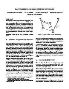
Architecture & express links An express link consists of a set of channels that are routed over multiple concatenated DWDM fiber links (or conduits) as illustrated in Fig. 1. At each intermediate node, the channels are not ter-
Lightpath Routing For routing shared-mesh protected lightpaths we can divide the problem of routing the lightpath into two parts: a) route the primary path, and b) route the backup path diverse from the primary path. When the optical network topology can have SRGs that are arbitrarily defined, then the problem of diverse routing is NP-complete as shown in Bouilet et al.3 Therefore, the selection of primary and backup routes are performed by a suitable heuristic that explores the space of primary and backup paths in an intelligent manner.
ThP5 Fig. 1. i) illustrates the physical layout of an express link between node A and node C that is glassed through at node B, an express link between node C and node E that is glassed through at node D, and an express link between node A and node E that is glassed through at nodes B, C, and D ii) illustrates the logical view of the network topology with assignment of SRGs and costs to links.
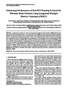
Channels on the primary path are dedicated to the lightpath, and carry traffic. Channels on the backup path are shared with other lightpaths in such a manner as to ensure single-failure protection. The routing of each lightpath will attempt to minimize the total cost of all channels in the lightpath route. A user defined cost is assigned to fiber-links that reflects the real cost of using a channel on that link. The costs of express links are assigned to assigned in a special way as follows. For routing the primary path, cost of each express link is set to be slightly less than the total cost of the underlying fiber links as illustrated in Fig. 2. Such a cost setting ensures that the express link is always preferred over the path through the underlying links by a shortest-cost path routing algorithm. In general, if there are multiple tiers of express links as in Fig. 1, then the cost of an express link between a node-pair is set to be slightly less than the cost of the shortest-cost path that uses the same underlying fiber links as the express link. Given a primary path, the backup path is routed to be SRG diverse from the primary path. For any link, its cost is set depending on the availability of a sharable channel on that link. Link costs are set as illustrated in Fig. 2: If there is a sharable channel on that link, then the cost is set to a fraction of the link cost, and if there is no sharable channel then the cost is set to the link cost. Results & Analysis We explore several different ways of setting costs to express links for routing the backup path. These approaches reflect the relative desirability of using a channel on the express-link versus using channels on the underlying fiber links of the express link. Table 1 illustrates the different cost functions for the express link, and the resulting backup path routing behavior. Note that, when the express link cost f(Ci), is less than the cost of underlying links:
冱i Ci, then, εf(Ci) < ε冱i Ci, and the express link will always be prefered over the underlying links when it is sharable. This is the case for the functions in rows 2, 3 and 4 in Table 1. There is a tradeoff in backup path routing: Routing on express links saves on ports, however, it may not allow for as many sharing opportunities (thereby incuring more protection capacity). On the other hand, routing on underlying links allows better sharing opportunities (thereby requiring less protection capacity) but requires more ports. However, routing always on underlying links prevents using sharable channels on express links if the demand allows sufficient sharing on the express link. By appropriately choosing the cost function for the express links, lightpath routing can be biased toward using the express link or using the underlying links, minimizing switch ports and bandwidth miles. We simulated the routing behavior on a backbone network topology with express links, with several different demand patterns. The results of these experiments are reported in Table 1 for two demand sets. The measures of the lightpath routing was the total number of ports used at all nodes, and the total bandwidth miles used on all
Thursday, March 21
Introduction This paper studies a wavelength-convertible core optical network1 consisting of backbone nodes with optical switches interconnected by point-topoint WDM fiber links in a mesh interconnection pattern. The optical network supports unprotected and shared-mesh protected lightpath services. Lightpaths are routed from a centralized management system that has access to the network inventory, including the topology and lightpath databases. A shared-mesh protected lightpath has a working route and a diversely routed backup route. The wavelength channels on the working route of the lightpath are dedicated for that lightpath and carry traffic under normal operating conditions. The wavelength channels on the backup route for the lightpath can be shared among different lightpaths in a way that ensures protection against any single-link or single-linkor-node failure.3 Diversity of routes in an optical network is defined using the notion of Shared Risk Groups.2 A set of optical channels that have the same risk of failure is called a Shared Risk Group (SRG). For example, all the channels that are multiplexed onto a WDM fiber-link is a shared risk group since the failure of the fiber-link simultaneously affects all the channels that are carried over the fiber. A set of optical channels between neighboring optical switches can, in general, belong to multiple SRGs. SRGs are configured by the network operator with the knowledge of the physical fiber plant of the optical network. A cost model assigns costs to links in the network that represents some cost of using the channel in a lightpath route (e.g., fiber-mileage). The quality of the lightpath route is the sum of costs of all channels in the route.
minated at the optical switch but are connected directly from one DWDM system (or conduit) to the next. Express links are also called “glassthrough links” since the optical channels are glassed through intermediate nodes. Each express link is assigned a set of SRGs that is union of the SRGs belonging to each fiber link traversed by the express link. For example, in Fig. 1 the SRGs assigned to the link AC is {S1,S2} which is the union of the SRGs assigned to link AB and link BC. Such an assignment of SRGs ensures that two routes that are supposed to be diverse will not use the express link, and any one of the underlying fiber links, since the failure of that underlying fiber link will result in the failure of both routes. A glass-through link transports express traffic between a pair of nodes, and saves ports on the intermediate optical switches. However, the channels on each underlying fiber link (used in the express link) cannot be used to cross-connect to other channels at intermediate nodes. Express links are used when a portion of the traffic pattern is expected to remain unchanged over long periods of time. However, when traffic patterns change over time, then at each node, the flexibility of being able to cross-connect any channels on adjacent WDM fiber links using the optical switch is desirable. In fact, networks designed with express links usually do not achieve the lowest cost from a total network optimization standpoint if one takes the demand churn into account. IP traffic tends to be more dynamic than legacy voice and private line traffic, and one would want to design an optical mesh network carrying IP traffic with all links going through optical switches at intermediate sites. This would maximize network reconfiguration flexibility and thus minimize total network cost over a large and varying set of traffic patterns.
504 / OFC 2002 / THURSDAY MORNING
ThP5 Fig. 2. i) & ii) illustrate the cost setting for an express link between node A and node E that is glassed through nodes B, C, and D. i) illustrates the cost setting for routing the primary path. The cost of the express link is set to be slightly less than the total cost of all underlying fiber links. ii) illustrates the cost setting for routing the backup path. The cost of an express link is a function of the costs of the underlying links. In addition, if a sharable channel is available, then the cost is set to be a fraction of the link cost. ThP5 Table 1. Different cost setting for routing backup paths on express links, and their resulting routing behavior. Results are reported for a representative topology with express links for two demand sets
Thursday, March 21
Express link cost function = f(Ci)
# switch ports Backup Path Routing Behavior
Bandwidth miles
Demand 1
Demand 2
Demand 1
Demand 2
Infinity Always route on underlying links δ Always route on express link (δ < Min (Ci))
824 846
3296 3384
92.2 K 103.4 K
368.8 K 413.8 K
ΣiCi – δ Route on underlying links if at(δ < Min (Ci)) least one of them can be shared, unless express link is sharable ΣiCi – E Route on underlying links if one (E ⬃ average (in some cases) or at least a certain cost of under- number of them are sharable, unlying link) less express link is sharable
632
2528
83.2 K
332.8 K
636
2544
83.4 K
333.9 K
the links. Table 1 illustrates that always routing backup paths on the express links does not perform well, and always routing on underlying links is better but not the best. The best performing approach routes backup paths mostly on the underlying links, but allows routing on express link if a sharable channel is available. Conclusion We examined the routing of protected lightpaths in an optical network with express links. To enable diverse routing, SRGs are assigned to the express link to be the union of all the SRGs on the underlying links. We examined the cost setting on the express links for routing the primary and backup paths. For routing primary paths, the express link is always preferred over the underlying links. For routing backup paths, the desirability of using express links depends strongly on the traffic demand. We find that biasing the routing of backup paths to mostly use underlying links while allowing express links to be used in some cases performs well in terms of switch ports and bandwidth miles used. References 1. T.E. Stern, K. Bala, Multiwavelength Optical Networks: A Layered Approach, Prentice Hall, May 1999. 2. S. Chaudhuri, G. Hjalmtysson and J. Yates, “Control of Lightpaths in an Optical Network”, Optical Internetworking Forum, OIF 2000.004.0, Jan 2000. 3. E. Bouillet, et al. “Routing and Restoration Architectures in Mesh Optical Networks”, Optical Networks Magazine, To Appear.
age signal power, and PN is the average noise power. However, the representation of the channel capacity in the standard form (1) is unsuitable for applications to the actual fiber optics systems. It was obtained based on the assumption of linearity of the communication channel, while the modern fiber optics systems operate in a substantially nonlinear regime. Since the optical transmission lines must satisfy very strict requirements for bit-error-rate (10–12 to 10–15), the pulse amplitude should be large enough so that is can be effectively detectable. The increase of the number of wavelength-division multiplexing (WDM) channels2 in the modern fiber optics communication systems also leads to a substantial increase of the electric field intensity in the fiber. As a consequence, the Kerr nonlinearity of the fiber refractive index n = n0 + γI (where I is the pulse intensity) becomes substantial and should be taken into account. In the present work we consider corrections to the channel capacity of the optical fiber communication system, originating from the nonlinearity of the fiber. The technique that we use involves a perturbative computation of the relevant mutual information and subsequent optimization. According to the Shannon’s basic result,1 the channel capacity is given by the maximum value of the mutual information per second over all possible input distributions: C = maxpx{H[y] – 具H[y x]典px}
(2)
The mutual information: R = H[y(ω)] – 具H[y(ω)x(ω)]典px
ThQ
2:00 pm–3:30 pm Ballroom A
Fiber Transmission Issues
(3)
is a functional of the “input distribution” px[x(ω)], which represents the encoding of the information using the electric field components at different frequencies:
冕 dω x(ω)exp(iωt) 0
Ein(t) =
Paul A Williams, NIST, USA, Presider
ThQ1
2:00 pm
The Channel Capacity of a Fiber Optics Communication System Evgenii Narimanov, Electrical Engineering Department, Princeton University, Princeton NJ 08544 Partha Mitra, Bell Laboratories, Lucent Tech., 600 Mountain Ave., Murray Hill NJ 07974 The performance of any communication system is ultimately limited by the signal to noise ratio of the received signal and available bandwidth. This limitation can be stated more formally by using the concept of channel capacity introduced within the framework of information theory.1 The channel capacity is defined as the maximum possible bit rate for error-free transmission in the presence of noise. For a linear communication channel with additive noise, and a total signal power constraint at the input, the capacity is given by the celebrated Shannon formula:1
冢
P0 C = W log 1 + ᎏ PN
冣
(1)
where W is the channel bandwidth, P0 is the aver-
(4)
W
The information entropy1 H[y(ω)] is the measure of the information received at the output of the communication channel. However, if the channel is noisy, for any output signal there is some uncertainty of what was originally sent. The conditional entropy H[y(ω)x(ω)] at the output for a given x(ω) represents this uncertainty. The calculate the channel capacity one needs to find the “input-output” relation for the communication system. For the fiber optical channel, the time evolution of the electric field E(z, t), where z is the distance along the fiber, can be accurately described in the “envelope approximation”,2 when: E(z, t) = A(z, t) exp(i(β0z – ω0t)) + c.c. (5) where the function A represents the slowly (compared to the light frequency) varying amplitude of the electric field in the fiber. The evolution of A(z, t) is described by the equation: ∂A ∂A i ∂2A α ᎏ + β1 ᎏ + ᎏ β2 ᎏ + ᎏ A = iγA2A (6) ∂z ∂t 2 ∂t2 2 Here the coefficients β describe the frequency dependence of the wavenumber (the fiber dispersion), α represents the effective absorption (compensated by the optical amplifiers), and γ defined