AbstractâDue to the growing importance of coastline surveil- lance and protection, underwater communication is playing an increasingly important role in ...
2022
IEEE JOURNAL ON SELECTED AREAS IN COMMUNICATIONS, VOL. 29, NO. 10, DECEMBER 2011
Routing TCP Flows in Underwater Mesh Networks Chin-Ya Huang, Parameswaran Ramanathan, Fellow, IEEE, and Kewal Saluja, Fellow, IEEE
Abstract—Due to the growing importance of coastline surveillance and protection, underwater communication is playing an increasingly important role in military networks. As compared to terrestrial networks, large propagation delays and low data rates are fundamental characteristics of underwater communication. Furthermore, due to some key differences in the factors causing fluctuations in the quality of the underwater channels, the corresponding communication links experience more prolonged data rate changes as compared to those in terrestrial networks. Large propagation delays and prolonged link data rate deteriorations severely degrade the end-to-end performance of Transmission Control Protocol (TCP) based applications. Since military applications often require the reliable data delivery provided by TCP, it is important to devise solutions to alleviate this problem. In this paper, we propose a new routing scheme called Linear Coded Digraph Routing (LCDR) to enhance the end-toend throughput of TCP based packet flows in underwater mesh networks. LCDR is a fully distributed scheme designed to locally respond to changes in the link data rates. In LCDR, each ingress node forwards packets after network coding. Each intermediate node adaptively uses network coding before forwarding the packets to the outgoing links. Each terrestrial gateway decodes the network coded packets before forwarding them to terrestrial networks. Each node adapts its packet forwarding rate based on the available bandwidth on the outgoing links, such that the terrestrial gateway can successfully receive packets with higher probability without significantly affecting cross-traffic. The effectiveness of the proposed scheme is evaluated using simulation. The simulation results show that the proposed scheme uses the spare bandwidth on each link efficiently and it significantly improves end-to-end throughput of TCP flows.
Three key differences are as follows. First, underwater communication must occur over acoustic channels because radio signals do not propagate well in water. Since acoustic signals travel in water at a very low speed of approximately 1500 m/s, as compared to radio signals’ air speed of 3 × 10⁸ m/s, the link propagation delays are several orders of magnitude larger in underwater networks than in terrestrial networks. Second, due to a lack of adequate frequency bandwidth in the acoustic spectrum, the link data rates in underwater networks are much smaller compared to those in terrestrial networks. For example, link data rates in underwater networks are typically less than 100 Kbps as compared to approximately 100 Mbps in IEEE 802.11n wireless networks. Third, the quality of an acoustic communication channel fluctuates significantly over time due to multipath, Doppler, and other fading effects. The time scales of channel fluctuations are much larger in underwater networks than in terrestrial networks because the underlying causes are considerably different. For example, underwater communication channels are often adversely affected by phenomena such as shadow zones, surface scattering, air bubbles, noise due to breaking waves, biological sources, and rain [5, 6]. The effects of factors such as winds, currents, and turbulence are also quite different for acoustic channels in water as compared to those for radio communication in air.
U
Due to these fundamental differences, recent research has focused on new medium access control (MAC) protocols and new routing protocols tailored for underwater networks [6– 18]. In this paper, we first show that in the underwater communication channels, the end-to-end performance of transport layer protocols like Transmission Control Protocol (TCP) is not satisfactory even with state-of-the-art lower layer protocols. We then propose a new network layer protocol called Linear Coded Digraph Routing (LCDR) and demonstrate that it results in considerable improvement in end-to-end TCP throughput.
Manuscript received 15 November 2010; revised 1 May 2011. C.-Y. Huang, P. Ramanathan, and K. Saluja are with the Department of Electrical and Computer Engineering, University of Wisconsin, Madison, WI, 53706 USA (e-mail: {chinya, parmesh,saluja}@ece.wisc.edu). Digital Object Identifier 10.1109/JSAC.2011.111212.
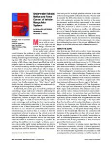
Since reliable data delivery is important for surveillance and tactical decision-making, improving the performance of TCP-based applications is of critical significance to military networks. Specifically, we consider an underwater acoustic mesh network (UAMN) through which a large number of surveillance nodes (SNs) upload their data to terrestrial military locations for further analysis (see Figure 1). Many SNs are mobile, and each node may carry a variety of sensing devices, including video cameras, to continuously survey and monitor a geographic area of interest. At any given time, each SN is associated with one of the stationary “mesh nodes” (MNs) in the UAMN. Some of the MNs (henceforth, referred to as gateway nodes) have direct connection to terrestrial networks. Forwarding of data from an MN to a gateway node occurs over one or more intra-mesh communication, i.e., an MN forwards
Index Terms—Underwater acoustic networks, military surveillance, sensor networks, mesh networks, multipath routing, network coding, TCP.
I. I NTRODUCTION NDERWATER communications has always been an integral part of military networks. Until recently, the primary focus of underwater military communication was on point-topoint information exchange between two sites, (e.g., between a submarine and a command center). However, in recent years, there has been a growing interest in the design of more complex underwater communication networks due to the increasing importance of coastline defense. Recent advances in underwater sensing technology have also contributed to this growing interest. There are, clearly, several fundamental differences between underwater and terrestrial communication networks. These differences are nicely articulated in several recent papers [1–5].
c 2011 IEEE 0733-8716/11/$25.00 �
HUANG et al.: ROUTING TCP FLOWS IN UNDERWATER MESH NETWORKS
2023
3
: Radio Signal
Water Surface
H
G
TCP Throughput hput (Kbps) Kbps)
: Acoustic Signals
2.5 2 15 1.5 1 0.5 0 0 25 0.25
0 75 0.75
1 25 1.25
1 75 1.75
2 25 2.25
2 75 2.75
3 25 3.25
single link propagation dealy (sec) A
B C
: Terrestrial Gateway
Fig. 1.
: Surveillance Node
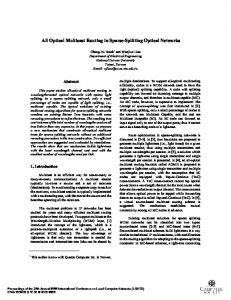
Fig. 2. Normalized TCP throughput under different propagation delay (sec). : Mesh Node
Example of underwater acoustic mesh network.
the data to other MNs, which in turn, forward it further until the data reaches the desired gateway node. The gateway node then uses the terrestrial network to forward the data to the desired military location. Typically, communication between two MNs occurs at much higher data rates compared to that between an SN and an MN. However, due to considerable fluctuations in channel quality, the data rates of a direct communication link between two MNs varies considerably over time. This variability in data rates degrades the end-to-end throughput of TCP based packet flows. For instance, when the data rate of communication links in a UAMN decreases, TCP flows passing through those links experience packet reordering, packet losses, and timeouts. In response, the corresponding TCP sources reduce their sending rates and re-transmit the lost packets. Although packet reordering, packet losses, and timeouts also occur in terrestrial networks, their effect on the end-to-end throughput of TCP flows is significantly more adverse in underwater networks. Packet round trip time in underwater networks is significantly larger than that in terrestrial networks, and the round trip delays are in the order of tens of seconds in underwater networks as compared to few milliseconds in terrestrial networks. Consequently, the effective bandwidthdelay products for a single TCP flow in an underwater network is often much larger than that in a terrestrial network. This in turn severely degrades the end-to-end TCP throughput when data rates fluctuate [19, 20]. This issue is illustrated in Figure 2, which shows the endto-end throughput achieved in an example underwater network as a function of link propagation delay (i.e., bandwidthdelay products). To obtain these results, the network is kept the same, but the delay of each link is varied from 0.25 seconds to 3.5 seconds. The bandwidth of each link is kept at 4 Kbps for all results. Since acoustic signals travel at a speed of 1500 m/s in water, link propagation delays of 1-5 seconds are common in underwater networks. As can be seen, when link propagation delay is 0.25 seconds, TCP end-to-end throughput is 2.4 Kbps which is approximately 60% of the maximum possible throughput of 4 Kbps. However, as the
delay increases, the end-to-end throughput drops significantly. At a link propagation delay of 3.5 seconds, the throughput is only 0.8 Kbps, which is approximately 20% of the maximum possible throughput. To alleviate this problem, we propose a new approach called LCDR, which forwards TCP packets in UAMNs. Through simulations, we show that LCDR performs considerably better than comparable schemes from literature. LCDR integrates several ideas into a fully-distributed scheme implemented through each node in a UAMN. First, it exploits multiroute diversity of a directed acyclic graph (DAG) within the UAMN to take advantage of the available bandwidth at many links in the network. Second, each node in the UAMN performs inter-session network coding of TCP packets before forwarding them on the appropriate outgoing links. Third, each node exploits the excess bandwidth available on an outgoing link to introduce packet redundancy through network coding in order to provide easy recovery from packet losses within the UAMN. Fourth, each node includes a buffer management strategy to ensure fair sharing of the limited storage and the excess bandwidth on an outgoing link among competing packet flows. Although individually each of the above four ideas have been exploited in literature in different contexts, their novel integration in a UAMN results in a fully-distributed strategy that effectively combats the channel quality fluctuation effects in underwater networks. The rest of this paper is organized as follows. We describe the related work in Section II. The proposed scheme is presented in Section III. Simulation results evaluating the proposed strategy are shown in Section IV. The paper concludes with Section V. II. R ELATED W ORK Over the past five years, there has been a resurgence of interest in underwater communication. Research groups at institutions such as the University of Connecticut, the University of California–Los Angeles, and Georgia Tech, have recently published a large number of papers in this area [1–5, 7–17, 21– 23]. These papers can be broadly classified based on the layer of abstraction of their focus: physical layer [21–23], link layer [7, 8], or network layer [9–12, 14, 15, 18, 24, 25]. The focus of this paper is the latter, network layer. Network layer solutions for underwater communication have taken a variety of approaches. For instance:
2024
IEEE JOURNAL ON SELECTED AREAS IN COMMUNICATIONS, VOL. 29, NO. 10, DECEMBER 2011
source directed routing [24, 25], location based routing [9–12] and • energy efficiency incorporated routing [14, 15, 18]. However, none of these routing schemes exploit the idea of network coding to increase the probability of successful packet delivery. Furthermore, none of them specifically consider the impact of their solutions on TCP flows. We show in Section IV that, due to the characteristics of underwater communication, TCP flows experience severe performance degradation and approaches such as multipath routing [9–12, 15, 16] are not adequate to alleviate these problems. However, as underwater mesh networks are essentially comprised of infrastructure nodes which are usually provisioned with long-term energy sources, we will not consider energy efficiency issues because our focus is on the networks themselves. Similar to other researches, we consider the possibility of transmitting redundant packets to increase the likelihood of successful packet delivery. This was done by [17], in which a protocol for reliable delivery of packets was proposed. The feedback information in Automatic Repeat Request (ARQ) is used by the sender to adapt the amount of redundancy introduced through Forward Error Correction (FEC). This approach, however, does not consider the impact of solution on TCP flows. Furthermore, due to the large round-trip delays in underwater networks, the feedback information is often stale and the amount of redundancy introduced by FEC does not match the network’s need at that time instant. In contrast, in our scheme, each node adapts the amount of redundancy introduced through network coding solely based on locally available information. Hence, it responds better to local congestions and changes in link data rates due to channel quality fluctuations. In [15, 16], multipath routing and network coding are integral parts of the proposed solution. They use power control and the broadcast nature of the underwater communication channel to adapt the amount of redundancy introduced through network coding. The main difference between these solutions in [15, 16] and our paper is in the assumed architecture of the underwater network. Our work focuses on routing in underwater meshes. Since the density of the mesh nodes is not likely to be large when compared to an extensive sensor network, power control is not an effective technique for controlling redundancy in our architecture. Furthermore, mesh nodes aggregate traffic from many SNs. As a result, our approach is able to exploit inter-flow network coding whereas the schemes in [15, 16] basically rely on intra-flow network coding. As with most other research in underwater networks, these two papers also do not consider their impact on the performance of TCP flows. To the best of our knowledge, there is only one paper which has considered the challenges of underwater communication on TCP flows [26]. The scheme in [26], called TCP-Hybla, addresses the challenge of large round-trip delays by modifying the algorithm for RTT selection in TCP. There are about five recent papers which deal with both network coding and TCP [27–31]. In a classic study of TCP and network coding [27], the authors propose a modification to the protocol stack at the TCP sender and receiver to introduce a new network coding sublayer between the transport and •
•
network layers. The new sublayer encodes/decodes segments transmitted/received by TCP sender/receiver. Modification of protocol stack at the sender and receiver of a TCP flow in underwater networks may not be desirable. In addition, unlike [27], in our scheme, network coding is done across multiple TCP flows. Further, other nodes in the mesh network also perform inter-flow network coding to improve TCP performance. Our scheme also incorporates new ideas in buffer management and redundancy management. In [27], redundancy management is done at the TCP sender. It requires the sender to collect information and estimate the spare bandwidth available in the route to determine how many redundant packets can be transmitted. The authors of [27] propose an indirect way to manage redundancy at the sender using the feedback (i.e., acknowledgments) inherent in some protocols (e.g. TCP), although the scheme in [28] is described for a single hop broadcast scenario with multiple receivers. If too many redundant packets are transmitted, then congestion will increase and the end-to-end throughput will suffer. On other hand, if too few redundant packets are transmitted, then they will not be effective in recovering from packet losses. In contrast, our approach does not require any single node to aggregate and be explicitly aware of the amount of spare bandwidth in the network. It occurs implicitly based on local information at each node. In addition to inter-flow network coding, this is another major advantage of our approach as compared to the one in [27]. III. L INEAR C ODED D IGRAPH ROUTING (LCDR) S CHEME A. Overview Consider a UAMN with one more terrestrial gateway node as shown in Figure 1. The traffic from an SN to a particular gateway G enters the mesh through an ingress node such as A, traverses one or more hops in the mesh network to node G and then goes over a terrestrial network to the receiving host. Let FA,G denote the set of TCP flows originating at SNs connected to node A destined to military locations reachable through gateway G. Below, we describe the idea in terms of the actions taken by the mesh nodes in forwarding the packets in FA,G . The proposed scheme, LCDR, consists of four key components, multipath routing, local sequencing, forward error correction, and mesh network coding. 1) Multipath Routing (MR): Instead of forwarding packets in FA,G over a single path, LCDR finds a directed acyclic graphic (DAG), GA,G rooted at node A and ending at node G. Packets in FA,G are routed from A to G over the links in GA,G . Only the sub-graph GA,G of UAMN is relevant to flows in FA,G . 2) Local Sequencing (LS): Due to differences in propagation delays, queuing delays, and in the number of hops, packets traversing different paths in the digraph will experience different delays in going from node A to node G. As a result, segments from a particular TCP flow will often not arrive in order at the corresponding receiver. Since TCP sources consider significant segment reordering as an indicator of congestion, they reduce their sending rates and thereby degrade their end-to-end throughput. Local Sequencing (LS)
HUANG et al.: ROUTING TCP FLOWS IN UNDERWATER MESH NETWORKS
is one possible solution to alleviate this problem. In LS, each mesh node buffers and locally sequences the packets before forwarding. As a result, the underlying TCP flows do not experience as much segment reordering as compared to a simple multipath routing scheme. Thus, a scheme, MR+LS, which includes both MR and LS is likely to have much better performance than a scheme based solely on MR. 3) Forward Error Correction at Ingress Node (FEC): In traditional MR+LS, a node simply forwards the packets it has received along one of its outgoing links in the routing DAG. If some of these packets are either corrupted or dropped in the mesh due to either higher bit error rate and/or due to congestion caused by lower data rate on a communication link, then the underlying TCP flows will experience segment losses. Since TCP sources reduce their sending rates in response to segment losses through either Fast Retransmission or timeouts, there is corresponding degradation in end-to-end throughput. One possible way to alleviate this problem is to introduce forward error correction. For example, an ingress node in the UAMN can create and forward redundant packets into the mesh in the hopes that a sufficient number of packets will reach the gateway node to recover the packets dropped in the UAMN. Such an approach will be completely transparent to the TCP sources and receivers. For instance, the ingress node can use network coding to create redundant packets through random linear combination of packets in its queue before forwarding them in the routing DAG. Since the ingress node may not be aware of the maximum flow rate available for a particular flow in the routing digraph, the node must estimate the amount of redundancy to be introduced. Too little redundancy may prevent loss recovery at the gateway node and too much redundancy can cause congestion in the UAMN. Nevertheless, with judicious use of forward error correction, the end-to-end performance of TCP flows can be improved. Hence, a scheme, MR+LS+FEC, which includes MR, LS, and FEC is likely to have better performance than MR+LS. 4) Mesh Network Coding with Buffer Management (MNC): The forward error correction introduced by an ingress node can be further enhanced using network coding at intermediate mesh nodes in the routing digraph. In particular, instead of simply forwarding the packets it receives, an intermediate mesh node may first linearly combine appropriate packets in its queue and then forward the resulting packets on an outgoing link in the routing digraph. By using random linear codes, an intermediate node can generate additional redundant packets in order to help the gateway node recover the packet losses in the UAMN. Of course, here again, the challenge is to control the amount of redundancy in such a way that the buffers at the subsequent nodes in the routing digraph are not unnecessarily overwhelmed by the additional redundant packets. In particular, if an intermediate mesh node i forwards as many packets as possible on its outgoing link to node j, then the buffer at node j may get filled up by packets from node i. A full buffer will cause packet losses to flows in FA,G , thereby decreasing the performance of flows in FA,G . Also, it is unfair to other flows in the UAMN. Therefore, each node must implement a buffer management strategy which ensures that no particular set of flows can dominate the buffer space at
2025
any node in the UAMN. The buffer management strategy must give higher priority to packets which are likely to contribute to loss recovery at the gateway node and lower priority to other packets. Although the advantages of the above four components are relatively easy to comprehend, it is clear that a careful integration is needed to fully exploit their capabilities. Such a careful integration is performed in the proposed scheme, LCDR1 . In the rest of this section, we describe LCDR from the perspective of three different types of nodes: ingress node A, intermediate node i, and gateway node G. B. Description of LCDR 1) LCDR at ingress node A: The algorithm given in Figure 3 describes the steps taken by node A during the time interval [kT, (k + 1)T ), where T is a pre-determined design parameter based on the time required to transmit a packet and the time required to network code a certain number of packets. Each step in Figure 3 has a tag to indicate the corresponding component. At the start of the interval, A discards all packets in FA,G which arrived in the interval [(k − 2)T, (k − 1)T ). In this time interval, node A transmits packets in FA,G which arrived during the interval [(k − 1)T, kT ). Packets in FA,G which arrive during the interval are simply buffered for later transmission. All packets transmitted during this interval have a special label with value k. The other nodes can identify this set of packets using this label. Let nAG,k be the total number of packets in FA,G which arrived during [(k −1)T, kT ). Then, node A first transmits these packets (without network coding) as in traditional multipath routing. That is, as and when, an outgoing link in the routing digraph becomes available, one of these packets is forwarded. However, unlike traditional multipath routing, these packets are not discarded until time (k + 1)T . In order to assist buffer management policy, the first nAG,k packets transmitted by A during this interval are marked as “High priority”. If time remains in the interval [kT, (k + 1)T ), then node A transmits redundant packets. The redundancy is generated using network coding. That is, node A performs a random linear combination of the nAG,k packets and forwards the result as a “Low priority” packet with label k. As described later, other nodes will give preferential treatment to “High priority” packets if their buffers are full. The rationale of using two priority levels is as follows. The “High priority” packets are transmitted without encoding. These packets can be forwarded to their receivers without any decoding, and thus irrespective of other packets. Some of these packets may not reach the gateway due to either packet errors or buffer overflow. The “Low priority” packets, which are linear combinations of the high priority packets, may be used to recover the lost high priority packets. Example: Consider an ingress node A, as shown in Figure 4. Suppose node A has two outgoing links into the mesh. Assume that the packets can be routed on both of these links to reach gateway nodes G and H in the mesh. Several SNs are connected to ingress node A, and some of the traffic is 1 In the rest of this paper, we sometimes refer to LCDR as MR+LS+FEC+MNC to clarify that it contains all the four components.
2026
IEEE JOURNAL ON SELECTED AREAS IN COMMUNICATIONS, VOL. 29, NO. 10, DECEMBER 2011
Algorithm Ingress In time interval [kT, (k + 1)T ) 1. [LS: ] Discard all packets in FA,G which arrived in [(k − 2)T, (k − 1)T ). 2. [LS: ] Buffer all incoming packets in FA,G . 3. Let nAG,k be the total number of packets in FA,G which arrived in [(k − 1)T, kT ). 4. [MR;FEC: ] On each outgoing link, transmit (as permitted by the packet scheduler) packets in FA,G which arrived in [(k − 1)T, kT ). The first nAG,k are transmitted as is without network coding. The additional packets are a random linear combination of packets in FA,G which arrived in [(k − 1)T, kT ). Transmit no more than number of received packets within [(k−1)T, kT ). Attach a label k to each of these packets. 5. [MNC: ] Of all the packets in FA,G transmitted in [kT, (k + 1)T ), mark the first nAG,k packets as “High priority” and the rest as “Low priority”. Fig. 3.
Algorithm executed by the ingress node in LCDR.
destined towards gateway node G, while others are destined towards gate node H. As described in Figure 3, node A buffers the packets in FA,G which arrive in time interval [(k − 1)T, kT ) for forwarding in time interval [kT, (k + 1)T ). Suppose that node A received only five packets identified as a1 , a2 , a3 , b1 and b2 during interval [(k − 1)T, kT ). Packets a1 , a2 and a3 are destined towards gateway node G. Likewise, packets b1 and b2 are destined towards gateway node H. Then, the actions taken by node A in [kT, (k + 1)T ) in forwarding these packets can be explained as follows. Suppose that the order in which the scheduler at node A considers these packets for forwarding is as shown in Figure 4. More specifically, the first packet considered by the scheduler is a1 . Therefore, at time t0 , when an outgoing link is free to transmit a new packet, node A forwards a1 . Next, at time t1 , the scheduler considers, and forwards, packet b1 . Similarly, at times t2 , t3 , and t4 , the scheduler considers packets b2 , a2 , and a3 and thus forwards them as is on the available outgoing link. In the traditional approach, the scheduler will be finished after transmitting these five packets. In contrast, in LCDR, node A continues to forward packets derived from these packets until time (k + 1)T . For instance, at time t5 , node A returns to the first packet considered by the scheduler, namely a1 , and forwards a linear combination, f1 , of a1 , a2 , and a3 , i.e., a network coded packet containing information from three packets destined towards gateway G. Then, at time t6 , node A returns to the second packet considered by the scheduler, namely b1 . This time it forwards a linear combination, g1 , of b1 and b2 , i.e., packets which are destined towards gateway node H. At time t7 , node A returns to the third packet considered by the scheduler, namely a2 . This time, it forwards a linear combination f2 of a1 , a2 , and a3 . Thus, in this example, node A has forwarded two redundant packets which are linear combination of a1 , a2 , and a3 , and one redundant packet which is a linear combination of b1 and b2 . The forwarding of redundant packets helps the mesh cope with fluctuations in bandwidth. At time (k + 1)T , node A will remove packets a1 , a2 , a3 , b1 , and b2 from its buffer and switch to forwarding packets which arrived in interval [kT, (k + 1)T ). Note that, all packets forwarded by node A in the interval [kT, (k + 1)T ), will have a label k so that the mesh nodes can identify the packets which can be network coded.
Gateway, G Gateway, H
Buffer of A a3 a2 b2 b1 a1 Outgoing Link 1
a1 0
Ingress node, A
b2 2
Outgoing Link 2
a2 3
b1 1
f1(a1,a2,a3) g1(b1,b2) 5
4
kT Discard all packets arrived in [ (k-2)T, (k-1)T)
Fig. 4.
Time
6
a3
a2(a1,a2,s3) 7
Time
(k+1)T Discard all packets arrived in [ (k-1)T, kT)
Illustration of LCDR at ingress node.
2) LCDR at intermediate node i: Figure 5 describes twopart process taken by intermediate node i with respect to the packets in FA,G . The first part describes the actions taken when a new packet in FA,G arrives. The other part describes the strategy used for transmitting packets on outgoing links. The process relies on a self-clocking scheme with respect to labels. Packets in FA,G arrive on each incoming link in non-decreasing order of label values. Therefore, when a packet labeled Ll arrives on incoming link l, node i knows that it will not receive any packet with label value less than Ll on that incoming link. Additionally, node i knows that it will not receive any packet with label less than k = min{Ll : incoming l}. Hence, node i starts processing packets with label k − 1. Node i also implements a buffer management strategy. In this strategy, preference is given to “High priority” packets if the buffer is full. The transmission strategy at an intermediate node is similar to that at an ingress node. The node first transmits the “High priority” packets “as is” without network coding. Then, if time permits, it transmits “Low priority” packets. Each of these low priority packets is a linear combination of all (both high and low priority) packets in FA,G with the current label. Example: Consider a typical node i in the mesh which is on the routing DAG for all traffic from node A to gateway G. Node i receives packets in FA,G with label k − 1. As shown in Figure 6, node i keeps buffering these packets until it has received a packet with label k on each of its incoming links in the corresponding DAG. When node i has received a packet with label k on each of its incoming links, it discards all packets with label k − 2 from its buffer. This is because it now knows that it will not receive any packet in FA,G with label k − 1. Using a traditional approach, node i simply forwards one copy of the packet it has received on an outgoing link in the routing DAG. In contrast, in LCDR, node i may also linearly combine all packets with label k−1 and forward them on an outgoing link. Suppose node i has received p packets in FA,G with label k − 1, and suppose h out of these are “High priority” packets. Then, using a traditional approach, node i will forward exactly p packets on its outgoing links. In contrast, in LCDR, node i first strives to forward the h high
HUANG et al.: ROUTING TCP FLOWS IN UNDERWATER MESH NETWORKS
Algorithm Intermediate When a packet in FA,G arrives on incoming link l: 1. [MNC: ] If buffer is full; 2. [MNC: ] If incoming packet is marked as “Low priority” 2. [MNC: ] Discard the incoming packet; 3. [MNC: ] Else 4. [MNC: ] If all packets in buffer are marked as “High priority” 5. [MNC: ] Discard incoming packet; 6. [MNC: ] Else 7. [MNC: ] Find the most recent “Low priority” packet in buffer and discard it. Enqueue incoming packet. 8. [LS: ] Let Ll by the largest label of all packets in FA,G received on incoming link l. 9. [LS: ] Let k = min{Ll : incoming l}. 10. [LS: ] Discard all packets in FA,G in buffer with label smaller than k − 2. On each outgoing link : 11. [MNC: ] Let n denote the number of “High priority” packets with label k-1 in the buffer. 12. [MR, MNC: ] Transmit (as permitted by packet scheduler) packets in FA,G with label k-1 in buffer. First, transmit the “High priority” packets as is without network coding. If time does not permit transmission of all these “High priority” packets, then discard the rest. If additional time is available after the “High priority” packets have been transmitted, then transmit random linear combinations of all packets in FA,G with label k-1. The total number of packets in FA,G transmitted with k-1 is no more than number of received packets of label k. Attach label k-1 to each of them. 13. [MNC: ] Of all the packets in FA,G transmitted with label k-1, mark the first n as “High priority” and rest as “Low priority”. Fig. 5.
Algorithm executed by the intermediate node in LCDR.
priority packets. It then forwards as many linearly combined copies as possible until it is time to switch to label k. Each of these forwarded copies will also have label k − 1. If the available bandwidth on its outgoing links does not allow node i to transmit h high priority packets, then it forwards fewer than h. On the other hand, if the available bandwidth on its outgoing links allows node i to transmit more than h packets, then it forwards network coded packets, even though some of them may be redundant. The high priority packets continue to be tagged as high priority while the network coded packets are tagged as low priority. In LCDR, mesh nodes such as node i must also perform buffer management. If a low priority packet arrives on an incoming link when its buffer is full, then the packet is discarded. However, if a high priority packet arrives on an incoming link when its buffer is full, then node i drops the most recently arrived low priority packet from its buffer to make space for incoming high priority packets. 3) LCDR at gateway node G: Figure 7 describes the steps taken by gateway node G. Node G also implements a buffer management strategy similar to intermediate node i. Similarly, node G also uses a self-clocking algorithm to determine which packets it can attempt to decode. If decoding is successful, the unencoded packets are forwarded through the terrestrial network. Otherwise, only the high priority packets are forwarded through the terrestrial network since the other packets are not recoverable. The decoding scheme is as in [32]. To enable decoding, each encoded packet includes coding coefficients in a special header. The coding coefficients from all received packets with the same label are used to construct an encoding matrix. The packets can be successfully decoded if and only if this matrix
2027
Time
Time
Fig. 6.
Illustration of LCDR at intermediate node.
Algorithm Gateway When a packet in FA,G arrives on incoming link l: 1. [MNC: ] If buffer is full; 2. [MNC: ] If incoming packet is marked as “Low priority” 2. [MNC: ] Discard the incoming packet; 3. [MNC: ] Else 4. [MNC: ] If all packets in buffer are marked as “High priority” 5. [MNC: ] Discard incoming packet; 6. [MNC: ] Else 7. [MNC: ] Find the most recent “Low priority” packet in buffer and discard. 8. [MNC: ] Enqueue incoming packet. 9. [LS: ] Let Ll by the largest label of all packets in FA,G received on incoming link l. 10. [LS: ] Let k = min{Ll : incoming l}. 11. [LS: ] Discard all packets in FA,G in buffer with label smaller than k-2. On each outgoing link : 12. [FEC, MNC: ] Apply decoding algorithm on packets in FA,G with label k-1. 13. [FEC, MNC: ] If the decoding algorithm succeeds, then transmit the recovered unencoded packets on the outgoing links as per routing algorithm. 14. [FEC, MNC: ] Else, forward the high priority packets and discard all packets in FA,G with label k-1. Fig. 7.
Algorithm executed by the gateway node in LCDR.
is invertible. The coefficients in the resulting inverse matrix are used to reconstruct the original packets [32]. Example: Consider a gateway node G which is receiving network coded packets from the SNs connected to ingress node A. Similar to Figure 6, node G buffers all packets with label k − 1 until it has received at least one packet with label k on each of its incoming links. When it has received at least one packet with label k on each of its incoming links, node G checks whether a sufficient number of linearly independent packets with label k−1 are present in its buffer to successfully recover the original packets. If there is a sufficient number, then node G performs the necessary decoding, recovers the original packets and forwards them to the terrestrial network. If there is not a sufficient number, then the high priority packets with label k − 1 are forwarded “as is” and all the packets with label k − 1 are discarded. Note that, this will result in a loss of some of the original packets from the SNs because they were not recoverable at the gateway node due to excessive losses in the UAMN.
2028
IEEE JOURNAL ON SELECTED AREAS IN COMMUNICATIONS, VOL. 29, NO. 10, DECEMBER 2011
' ��' ' ��' ' ' '
G
E
�� ��!�"#�$"� �%�$��
C
��
���� ���� ���� ���� ��� ���� ����
���
�
��� ��(� ���� ��(� ��� ���� ���
���� ���
����
� ��� ���� ���� ���( ����
���� ���� ���� ���� ���� �
���
�
���
B
D
Cross-traffic
�%
A
: Terrestrial Gateway
Fig. 8.
: Surveillance Node
�
���%
&%
&��%
'%
�%
(%
�) * �� � )��� ��$�� ��� �� �� � � ��
: Mesh Node
Simulation topology
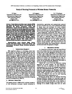
IV. E VALUATION A. Overview In this section, we present results of our experimental evaluation. The goals of this evaluation are two-fold. The first goal is to compare the performance of the proposed LCDR scheme to that of other schemes in literature under different scenarios. The second goal is to characterize the underlying reasons for LCDR’s performance improvement relative to other schemes. To meet these goals, we compare LCDR’s performance with three schemes: • Multipath Routing (MR) • Multipath Routing with Local Sequencing (MR+LS) • Multipath Routing, Local Sequencing and Forward Error Correction (MR+LS+FEC) These schemes represent the evolution of adding each component and show the gradual relative benefit gradually. Note that, some combinations of MR, LS, FEC and MNC are not meaningful (such as the combinations without MR). Other combinations are provably inferior to the combinations included in this paper. Performance evaluation of MR, MR+LS, MR+LS+FEC, and MR+LS+FEC+MNC (i.e., LCDR) are done using simulations in ns-2 [33]. MR required no significant modifications to ns-2. To evaluate MR+LS, MR+LS+FEC, and LCDR, we implemented the necessary algorithms in ns-2. B. Simulation Setup In this paper, we include results only for one mesh topology, as shown in Figure 8. Although we also simulated a number of other topologies and setups, we skip presenting them due to the high level of similarity in the results and conclusions. As can be seen, in Figure 8, there are six nodes labeled A, B, C, D, E and G. Node G is the terrestrial gateway. The SNs of interest are connected to ingress node A. For most simulations, there are ten SNs connected to node A, and each one has a TCP flow to
Fig. 9. Relative contribution of MR, LS, FEC and MNC to overall performance.
a terrestrial military location. We assume there are no packet losses in the terrestrial network. For ease of understanding, most experiments in this paper are conducted assuming that the underlying MAC protocol perfectly recovers all packet errors through a combination of FEC and ARQ. Consequently, in these cases, the packet losses are due only to buffer overflows. Further, the acoustic signals travel in water at 1500 m/s. Propagation delay of each link in the mesh is 1 second (approximately 1 mile between MNs), and the propagation delay between node A and an SN is 5 seconds (approximately 5 miles between an SN and an MN). The maximum flow rate from A to G remains approximately 45 Kbps throughout the simulation despite channel quality fluctuations. We model the channel fluctuation on a communication link using a two state (High-Low) Markov model. In the Low (High) state, the link data rate is assumed to be 20 Kbps (40 Kbps). In addition, some links may also have cross-traffic competing for bandwidth along with the TCP flows of interest. For most simulation results presented here, the cross-traffic is a UDP flow modeled as a ON-OFF Pareto source (i.e., ON times and the OFF times are chosen randomly using a Pareto distribution with specified parameters). C. Simulation Results a) Experiment 1: In this experiment, we explore the effect of spare bandwidth on the performance of the four routing schemes. Figure 9 shows the results for the four schemes in seven different cases. For these results, there are ten SNs, each with a TCP flow. All ten flows are long-lasting and well-established before the channels begin fluctuation. There is also UDP cross-traffic sharing the communication link from D to E with the following parameters: (i) ON and OFF times are Pareto distributed with means of 500 seconds, and 250 seconds, respectively, and a shape parameter value of 2.0, and (ii) the data rate is 18 Kbps when ON and zero when OFF. Thus, the long-term average data rate of the UDP cross-traffic is 12 Kbps.
HUANG et al.: ROUTING TCP FLOWS IN UNDERWATER MESH NETWORKS
MR
MR+LS
MR+LS+FEC
2029
MR+LS+FEC+MNC
23 2.3 2.1
R = 0.1
2
2.5
R = 0.2
R = 0.3
R = 0.4
R = 0.5
3.5
4
5
0.7 Normalized TCP Throughput
1.9
TCP Thrughputt (Kbps))
LCDR 0.8
1.7 1.5 1.3 11 1.1 0.9 07 0.7 0.5 500
1500 2500 3500 4500 5500 6500 7500 8500 9500 10500 time (sec)
0.6 0.5 0.4 0.3 0.2 0.1 0.0
(a) Large spare bandwidth. MR
MR+LS
MR+LS+FEC
MR+LS+FEC+MNC
3
6
link bandwidth (Kbps) between SN and MN
3
TCP Throughput hroughputt (Kbps))
Fig. 11.
2
1.5
1
0.5 500
1500
2500
3500
4500
5500
6500
7500
8500
9500 10500
time(sec)
(b) Moderate spare bandwidth. MR
MR+LS
MR+LS+FEC
MR+LS+FEC+MNC
3 TCP Throughput hroughput (Kbps)
Comparison of TCP throughput in LCDR and [27].
2.5
2.5 2 1.5 1 0.5 500
1500
2500
3500
4500
5500
6500
7500
8500
9500 10500
time (sec)
(c) Tight spare bandwidth. Fig. 10.
Performance of exploiting the effect of spare bandwidth.
As can be seen in Figure 9, the data rate of the acoustic link from SN to A varies from 2 to 6 Kbps. Specifically, each bar shows the contribution of each component of LCDR with the bottom to the top ordered as MR, LS, FEC and MNC, respectively. In the first five cases (i.e, between 2 and 4 Kbps), the ten TCP flows together cannot utilize the maximum flow rate from node A to node G. For example, when the SN-MN link is 3 Kbps, the maximum data rate entering the mesh through node A is 30 Kbps, whereas the maximum flow rate from A to G is approximately 45
Kbps2 . As a result, there is spare bandwidth for LCDR to exploit. As can be seen in Figure 9, even when a large amount of spare bandwidth exists (i.e., 2K and 2.5K bars in Figure 9), MR still performs poorly due to segment reordering. However, the throughput for MR+LS, MR+LS+FEC and MR+LS+FEC+MNC (LCDR) are almost the same. When the amount of spare bandwidth is moderate, congestion loss increases, and the performance of MR+LS is limited. Since FEC and MNC introduce redundant packets to recover from losses, MR+LS+FEC and MR+LS+FEC+MNC (LCDR) still perform well. In particular, MR+LS+FEC+MNC (LCDR) also exploits spare bandwidth in the mesh, and it performs significantly better than MR and better than MR+LS+FEC. However, when a bottleneck occurs in the mesh (i.e., the 5K and 6K bars), MR+LS+FEC+MNC (LCDR) is unable to introduce redundant packets and the performance advantage of MNC reduces. Therefore, MR+LS+FEC+MNC (LCDR) has comparable end-to-end throughput as MR+LS+FEC. Figures 10(a)-(c) show the variations in short-term throughput in the case of 3, 4, and 5 Kbps, respectively. Observe that MR+LS fluctuates considerably over time due to packet losses, especially as the mesh becomes the bottleneck. Specifically in the case of 3 Kbps, in which packet loss rate is small, the fluctuation in end-to-end throughput of MR+LS is not much. However, as the amount of spare bandwidth reduces, MR+LS experiences higher packet loss rate. Due to the large round-trip delays, TCP throughput takes a while to recover from the sending rate reductions caused by the packet losses. Since the gateway node recovers most of the packet losses in MR+LS+FEC and MR+LS+FEC+MNC (LCDR), their end-to-end throughput is more stable over time. We also compared the performance of LCDR to the proposed scheme in [27], in which network coding is also used to improve the TCP throughput in terrestrial networks. We investigated the performance under different redundancy factor values (R) in [27]. Specifically, Figure 11 shows the results for 2 We conducted simulations using very high data rate UDP flows and measured the maximum flow rate through the network to be around 45 Kbps.
2030
IEEE JOURNAL ON SELECTED AREAS IN COMMUNICATIONS, VOL. 29, NO. 10, DECEMBER 2011
MR MR+LS+FEC
2.5
MR+LS MR+LS+FEC+MNC (LCDR)
MR
MR+LS
MR+LS+FEC
MR+LS+FEC+MNC (LCDR)
3.5
TCP Throuhgpput (Kbps)
3
TCP Throughput (Kbps)
2
1.5
1
2.5 2 1.5 1 0.5 0
0.5
high-inf
2s
3s
4s
5s
low-inf
fluctuation interval (sec)
0
estableshed flows
new flow
Fig. 13.
(a) Long-term average throughput. MR 3
MR+LS
MR+LS+FEC
2 1.5 1 0.5 0 2500
3500
4500
5500
6500
Effect of mean duration of channel fluctuations.
MR+LS+FEC+MNC (LCDR)
2.5 TCP Throughput hroughput (Kbps)
1s
7500
8500
9500
time (sec)
(b) New flow short-term throughput. Fig. 12. Comparison of net TCP flow’s performance with that of established TCP floes.
R = 0.1, 0.2, 0.3, 0.4, and 0.5 in addition to the performance of our proposed scheme, LCDR. As can be seen, LCDR performs better than the scheme in [27] for any value of R as LCDR is able to exploit the available bandwidth on each link in the network. Hence, in LCDR, the number of redundant packets is controlled adaptively based on the spare bandwidth on each link. Note that it is difficult to adaptively select a value for R in [27], especially in underwater military networks, because: (i) adjusting R requires feedback on loss rates, and (ii) feedback is often stale due to large propagation delays. b) Experiment 2: In this experiment, there are nine SNs with established long-standing TCP flows with the tenth SN initiating a TCP flow. Figure 12(a) compares the end-to-end throughput of the newly initiated flow with the average of the end-to-end throughputs of the established flows. Figure 12(b) shows the variation in the end-to-end throughput of the new flow over time. Specifically, at time 2500, a new TCP flow is initiated. There is also UDP cross-traffic sharing the communication link from D to E, as was also seen in Experiment 1. We set the acoustic link from each SN to A at 4 Kbps. In Figure 12(a), observe that the performance of the new flow is comparable to that of the long established flows. For the same reasons as
in Experiment 1, the new flow for MR+LS experiences more throughput variation over time as shown in Figure 12(b). c) Experiment 3: In this experiment, we explore the impact of mean duration for channel quality fluctuations. For simplicity, mean High duration is kept equal to mean Low duration. In Figure 13, the y-axis is the average TCP throughput over ten flows, and the x-axis shows the mean fluctuation duration. In addition, Figure 13 includes results for high-inf and low-inf scenarios in which there are no channel fluctuations, and the channel stays at 40 Kbps and 20 Kbps, respectively. These two cases are included to show the extremes of mean duration for channel quality fluctuations. When channel fluctuation exists, TCP throughput of MR, MR+LS and MR+LS+FEC drops as the mean durations of channel quality fluctuations increase. However, LCDR (i.e., MR+LS+FEC+MNC) throughput is not particularly sensitive to the mean duration. Furthermore, when the mean duration is less than 2 seconds, LCDR slightly underperforms compared to MR+LS and MR+LS+FEC. This is because of the additional overhead of MNC adaptation. Specifically, some mesh nodes introduce redundant packets which are later dropped when the channel quality changes quickly. d) Experiment 4: In this experiment, we explore the sharing of spare bandwidth among multiple independent groups of TCP flows in LCDR. We assume that among ten SNs connected to A, five of them send TCP packets through G to the corresponding destinations. The other five SNs send their packets to another gateway node. TCP flows destined towards gateway G are not linearly combined with TCP flows destined towards the other gateway node. These two groups of encoded flows share the link bandwidths in the mesh network. Figure 14 shows the corresponding results. Clearly, both sets of flows have approximately the same TCP throughput, and these two set of flows share the network bandwidth equally between them. This further validates the claim that LCDR allows multiple competing TCP flows to co-exist in the network without adversely affecting their performances. e) Experiment 5: In Experiments 1-4, we consider the ideal case, in which the medium access protocol perfectly recovers all packet errors which occur in an acoustic link. Here, we investigate the effect of unrecoverable packet errors in each acoustic link. Packets, which do not get delivered to the TCP receivers due to these errors must be retrans-
HUANG et al.: ROUTING TCP FLOWS IN UNDERWATER MESH NETWORKS
TCP flow sets 1
2031
TCP flow set 2
MR
3.5
TCP Throughput roughput (Kbps)
TCP Throughput oughput (Kbps)
3 2.5 2 11.5 5 1 0.5 0 12000
MR+LS+FEC
LCDR
2 1.5 1 0.5 0
14000
16000
18000
20000
0
22000
time (sec) Fig. 14.
MR+LS
2.5
Bandwidth fair share among different TCP flow sets.
mitted by the TCP sender. According to TCP protocol, such retransmissions also invoke congestion control mechanisms, in which the sending rate is reduced. In MR and MR+LS, it is impossible to recover the packet loss due to these errors. As a result, their performance degrades considerably as packet error probability increases. In MR+LS+FEC, redundant packets are sent by ingress node A. Using these redundant packets, the gateway node G can recover some of the losses. Hence, its performance is slightly better than that of MR and MR+LS. In LCDR, redundant network encoded packets are adaptively sent by intermediate nodes in the UAMN. Consequently, the gateway node can recover much more packet losses compared to MR+LS+FEC. This results in significant performance improvement. V. C ONCLUSIONS Due to the large propagation delays of acoustic signals, factors such as packet losses and packet reordering have more adverse effects on end-to-end throughput of TCP flows in underwater networks than in terrestrial networks. In this paper, we propose a scheme for routing TCP flows in underwater mesh networks. The proposed scheme, called LCDR, addresses the problem of low TCP throughput using several ideas, including multiple path routing, local sequencing, network coding, and distributed redundancy management. We implemented our scheme in the network simulator ns-2 and evaluated its performance under different scenarios. The simulation results show that each of the above four ideas contribute substantially to the overall end-to-end performance. The evaluation also shows that the end-to-end TCP throughput is robust to the changes in the link data rates caused by fluctuations in the channel quality. In particular, the end-to-end throughput is not very sensitive to the mean duration of channel quality fluctuations. We believe that LCDR is an efficient and effective network layer approach for enhancing the performance of TCP flows in underwater military networks. R EFERENCES [1] Z. Peng, J.-H. Cui, B. Wang, K. Ball, and L. Freitag, “An underwater network testbed: design, implementation and measurement,” in Proceedings of the Workshop on Underwater Networks, 2007, pp. 65–72.
0.2
0.4
0.6
0.8
1
1.2
packet error probability (%) Fig. 15.
Effect of wireless packet loss.
[2] J. hong Cui, J. Kong, M. Gerla, and S. Zhou, “Challenges: Building scalable mobile underwater wireless sensor networks for aquatic applications,” IEEE Network, Special Issue on Wireless Sensor Networking, vol. 20, pp. 1–8, 2006. [3] I. F. Akyildiz, D. Pompili, and T. Melodia, “Underwater acoustic sensor networks: research challenges,” Ad Hoc Networks, vol. 3, no. 3, pp. 257–279, May 2005. [4] E. M. Sozer, M. Stojanovic, and J. G. Proakis, “Underwater acoustic networks,” IEEE Journal of Oceanic Engineering, vol. 25, no. 1, pp. 72–83, Jan. 2000. [5] J. Partan, J. Kurose, and B. N. Levine, “A survey of practical issues in underwater networks,” ACM SIGMOBILE Mobile Computing and Communications Review, vol. 11, pp. 23–33, Oct. 2007. [6] D. Pompili, T. Melodia, and I. F. Akyildiz, “A resilient routing algorithm for long-term applications in underwater sensor networks,” in Proceedings of Mediterranean Ad-Hoc Networking Workshop (MedHocNet), 2006. [7] S. Park, B. Jo, and D.-S. Han, “An efficient MAC protocol for data collection in underwater wireless sensor networks,” in Proceedings of Military Communications Conference (MILCOM), 2009, pp. 348–352. [8] N. Parrish, L. T. Tracy, S. Roy, P. Arabshahi, and W. L. J. Fox, “System Design Considerations for Undersea Networks: Link and multiple access protocols,” IEEE Journal on Selected Areas in Communications, vol. 26, no. 9, pp. 1720–1730, 2008. [9] P. Xie, J.-H. Cui, and L. Lao, “VBF: Vector-based forwarding protocol for underwater sensor networks,” in Networking, 2006, pp. 1216–1221. [10] N. Nicolaou, A. See, P. Xie, J.-H. Cui, and D. Maggiorini, “Improving the robustness of location-based routing for underwater sensor networks,” in OCEANS, Jun. 2007, pp. 1–6. [11] T. Hu and Y. Fei, “QELAR: A machine-learning-based adaptive routing protocol for energy-efficient and lifetime-extended underwater sensor networks,” IEEE/ACM Transactions on Mobile Computing, vol. 9, no. 6, pp. 796–809, 2010. [12] H. Yan, Z. J. Shi, and J.-H. Cui, “DBR: Depth-based routing for underwater sensor networks,” in Networking, 2008, pp. 72–86. [13] U. Lee, P. Wang, Y. Noh, L. F. M. Vieira, M. Gerla, and J.-H. Cui, “Pressure routing for underwater sensor networks,” in Proceedings of International Conference on Computer Communications (INFOCOM), 2010, pp. 1676–1684. [14] M. Zorzi, P. Casari, N. Baldo, and A. Harris, “Energy-efficient routing schemes for underwater acoustic networks,” IEEE Journal on Selected Areas in Communications, vol. 26, no. 9, pp. 1754–1766, Dec. 2008. [15] Z. Zhou and J.-H. Cui, “Energy efficient multi-path communication for time-critical applications in underwater sensor networks,” in Proceedings of the International Symposium on Mobile Ad hoc Networking and Computing (MobiHoC), 2008, pp. 221–230. [16] Z. Guo, B. Wang, and J. hong Cui, “Efficient error recovery with network coding in underwater sensor networks,” in Proceedings of IFIP Networking, 2007. [17] P. Xie and J.-H. Cui, “An FEC-based reliable data transport protocol for underwater sensor networks,” in Proceedings of International Con-
2032
[18]
[19]
[20] [21]
[22] [23] [24]
[25]
[26] [27]
[28] [29]
[30]
[31]
[32]
[33]
IEEE JOURNAL ON SELECTED AREAS IN COMMUNICATIONS, VOL. 29, NO. 10, DECEMBER 2011
ference on Computer Communications and Networks, Aug. 2007, pp. 747–753. H. Kim, J. Ryu, and K. Han, “A power efficient routing protocol in wireless sensor networks,” in Computational Science - ICCS, V. S. Sunderam, G. D. v. Albada, P. M. A. Sloot, and J. J. Dongarra, Eds., 2005, vol. 3515, pp. 585–592. H. Lee, S. hyeoung Lee, and Y. Choi, “The influence of the large bandwidth-delay product on TCP Reno, NewReno, and SACK,” in Proceedings of IEEE ICOIN on TCP Reno, NewReno, and SACK, 2001, pp. 1–14. R. Huang and A. Chien, “Benchmarking high bandwidth delay product networks,” University of California, San Diego, Tech. Rep., 2004. S. Mason, C. Berger, S. Zhou, and P. Willett, “Detection, synchronization, and doppler scale estimation with multicarrier waveforms in underwater acoustic communication,” IEEE Journal on Selected Areas in Communications, vol. 26, no. 9, pp. 1638–1649, Dec. 2008. G. Leus and P. van Walree, “Multiband OFDM for covert acoustic communications,” IEEE Journal on Selected Areas in Communications, vol. 26, no. 9, pp. 1662–1673, Dec. 2008. S.-J. Hwang and P. Schniter, “Efficient multicarrier communication for highly spread underwater acoustic channels,” IEEE Journal on Selected Areas in Communications, vol. 26, no. 9, pp. 1674–1683, Dec. 2008. J. M. Jornet, M. Stojanovic, and M. Zorzi, “Focused beam routing protocol for underwater acoustic networks,” in Proceedings of the ACM international workshop on Underwater Networks. ACM, 2008, pp. 75–82. R. Nitzel, C. Benton, S. Chappell, and D. Blidberg, “Exploiting dynamic source routing to enable undersea networking over an ad-hoc topology,” in Proceedings of the International Symposium on Underwater Technology, 2002, pp. 273–277. N. Iikubo, M. Nakatsuka, and J. Katto, “Improving TCP performance over underwater sensor networks,” in Proceedings of the International Workshop on UnderWater Networks, Sep. 2008. J. K. Sundararajan, D. Shah, M. M´edard, M. Mitzenmacher, and J. Barros, “Network coding meets TCP,” in Proceedings of International Conference on Computer Communications (INFOCOM), 2009, pp. 280– 288. J. K. Sundararajan, D. Shah, and M. M´edard, “Feedback-based online network coding,” submitted to IEEE Transactions on Information Theory, 2009. B. Radunovic, C. Gkantsidis, P. B. Key, and P. Rodriguez, “Toward practical opportunistic routing with intra-session network coding for mesh networks,” IEEE/ACM Transactions on Networking, vol. 18, no. 2, pp. 420–433, 2010. P. Samuel David and A. Kumar, “Network coding for TCP throughput enhancement over a multi-hop wireless network,” in Proceedings of the Third International Conference on COMmunication System softWAre and MiddlewaRE (COMSWARE), 2008, pp. 224–233. Y. Huang, M. Ghaderi, D. F. Towsley, and W. Gong, “TCP performance in coded wireless mesh networks,” in Proceedings of Communications Society Conference on Sensor, Mesh and Ad Hoc Communications and Networks (SECON), 2008, pp. 179–187. T. Ho, M. Medard, R. Koetter, D. Karger, M. Effros, J. Shi, and B. Leong, “A random linear network coding approach to multicast,” IEEE Transactions on Information Theory, vol. 52, no. 10, pp. 4413– 4430, Oct. 2006. “The Network Simulator NS-2,” http://www.isi.edu/nsnam/ns/.
Chin-Ya Huang received the B.S. degree in electrical engineering from National Central University, Taiwan, in 2004, the M.S. degree in communication engineering from National Chiao-Tung University, Taiwan, in 2006. She also received M.S. degrees in both electrical & computer engineering and computer science from University of WisconsinMadison, in 2008 and 2010, respectively. She is currently a Ph.D. candidate at University of WisconsinMadison. She is conducting research in the field of wireless communication and networks, which is under the supervision of Professor Ramanathan.
Parameswaran Ramanathan received the B. Tech degree from the Indian Institute of Technology, Bombay, India, in 1984, and the M.S.E. and Ph.D. degrees from the University of Michigan, Ann Arbor, in 1986 and 1989, respectively. Since 1989, Dr. Ramanathan has been faculty member in the Department of Electrical and Computer Engineering, University of Wisconsin, Madison, where he served as a Department Chair from 2005-2009. He leads research projects in the areas of sensor networks and next generation cellular technology. In 1997-98, he took a sabbatical leave to visit research groups at AT&T Laboratories and Telcordia Technologies. He was also a Visiting Professor at Kanwal Rekhi School of Information Technology, Indian Institute of Technology, Bombay, India in 2004. Dr. Ramanathan’s research interests include wireless and wireline networking, real-time systems, fault-tolerant computing, and distributed systems. He has served as an Associate Editor for IEEE Transactions on Mobile Computing, Associate Editor for IEEE Transactions on Parallel and Distributed Computing (1996–1999) and Elsevier AdHoc Networks Journal (2002–2005). He has also served on program committees of conferences such as Mobicom, Mobihoc, International Conferences on Distributed Systems and Networks, Distributed Computing Systems, Fault-tolerant Computing Symposium, Realtime Systems Symposium, Conference on Local Computer Networks, and International Conference on Engineering Complex Computer Systems. He was the Finance and Registration Chair for the Fault-tolerant Computing Symposium (1999). He was the program co-chairman of the Workshop on Dependendability Issues in Wireless Ad Hoc Networks and Sensor Networks, Workshop on Sensor Networks and Applications (2003), Broadband Wireless (2004), Workshop on Architectures for Real-time Applications, 1994 and the program vice-chair for the International Workshop on Parallel and Distributed Real-time Systems, 1996. He is the General Chair of Mobicom 2011. In 2009, he was elevated to Fellow of IEEE for his contributions to realtime systems and networks.
Kewal K. Saluja (SM’70–M’73–SM’89–F’95) obtained his Bachelor of Engineering (BE) degree in Electrical Engineering from the University of Roorkee, India in 1967, M.S. and Ph.D. degrees in Electrical and Computer Engineering from the University of Iowa, Iowa City in 1972 and 1973 respectively. He is currently with the Department of Electrical and Computer Engineering at the University of Wisconsin-Madison as a Professor, where he teaches courses in logic design, computer architecture, microprocessor based systems, VLSI design and testing, and fault-tolerant computing. Prior to this he was at the University of Newcastle, Australia. Professor Saluja has held visiting and consulting positions at various national and international institutions including University of Southern California, Hiroshima University, Nara Institute of Science and Technology, and the University of Roorkee. He has also served as a consultant to the United Nations Development Program. He was the general chair of the 29th Fault Tolerant Computing Symposium (FTCS) and he served as an Editor of the IEEE Transactions on Computers (1997-2001). He is currently the Associate Editor for the letters section of the Journal of Electronic Testing: Theory and Applications (JETTA). His research focus is in the areas of Digital Systems Testing, Fault-Tolerant Computing, and Sensor Networks. Professor Saluja has authored and co-authored over 300 technical papers that have appeared in refereed conference proceedings and journals. Professor Saluja is a member of Eta Kappa Nu, Tau Beta Pi, a fellow of the JSPS, and a Fellow of the IEEE.