Jul 31, 2001 - Foreign Application Priority Data. Jun. ... 327/161. See application ?le for complete search history. (56
USO0RE40205E
(19) United States (12) Reissued Patent Funaba et al. (54)
(45) Date of Reissued Patent:
SEMICONDUCTOR DEVICE AND TIMING CONTROL CIRCUIT _
(75) Inventors: Seiji Funaba, Chryoda-ku (JP); Yoji Nishio, ChiyOda-ku (JP); Yuichi Okuda, Chryoda-ku (JP); Yoshlnobu Nakagome, chlyoda-ku (JP) 73
( )
Assi nee: El ida Memo
g
P
ry,
2/2002 Hashimoto ................ .. 327/158 4/2002 Akioka et a1. . 365/194
6,525,585 B1 *
2/2003
JP
y ( )
Flled:
11427062
JP
Aug‘ 23’ 2002 Related U-s- Patent Documents
JPO Notice of Reason of Refusal dated Oct. 26, 2007, in Japanese W1th Engl1sh translatron.
6,269,051
_
JUL 31, 2001 09/640 670
Primary ExamineriTan T. Nguyen (74) Attorney, Agent, or FirmiReed Smith LLP; Stanley P.
Filed.
Aug 1,8 2000
Fisher, Esq.; Juan Carlos A. Marquez, Esq. (57) ABSTRACT
.
,
Division of application No. 09/563,160, ?led on May 1,
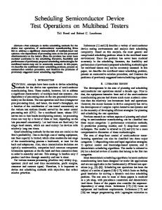
[Control on the speed of operation of a delay loop from the
2000, now Pat. NO. 6,212,127.
output of a variable delay circuit to a delay control input
(52) (58)
thereof is performed. For example, frequency-dividing cir
Foreign Application Priority Data
Jun. 18, 1999
(51)
_
Issued: APPI' NO‘:
U.S. Applications:
(30)
10/1997
* cited by examiner
Patent No.:
.
(62)
10/1997
11-127063
OTHER PUBLICATIONS
Reissue of: (64)
Iida et a1. ................. .. 327/279
FOREIGN PATENT DOCUMENTS 10412182 0/1996 10-283060 4/1997
JP JP
Inc., Tok 0 JP
Apr. 1, 2008
6,351,166 B2 * 6,366,507 B1 *
(21) Appl. No.: 10/226,019 (22)
US RE40,205 E
(10) Patent Number:
cuits are respectively placed at the input and output of the
variable delay circuit. A signal obtained by frequency
(JP) ......................................... .. 11-171864
dividing a signal outputted from the variable delay circuit is
Int. Cl. GIIC 11/4076
supplied to one input of a phase comparator through a
(2006.01)
dummy delay circuit, and a signal obtained by frequency dividing the input of the variable delay circuit is supplied to 327/ 161
the other input of the phase comparator. Phase control is performed according to the result of comparison between the
Field of Classi?cation Search ................ .. 327/161
phases of both signals.] Control on the speed of operation of
US. Cl. ..................... .. 365/194; 365/233; 327/158;
a delay loopfrom the output ofa variable delay circuit to a
See application ?le for complete search history. (56)
delay control input thereof is performed. For example, frequency-dividing circuits are respectively placed at the
References Cited
input and output of the variable delay circuit. A signal obtained by frequency-dividing a signal outputted from the
U.S. PATENT DOCUMENTS 5,430,394 A
*
5 939 913 A * 5’987’6l9 A
7/1995
McMinn et a1.
variable delay circuit is supplied to one input ofa phase . . .
.......... .. 327/292
8/1999 Tomita
* “H999
'''
327/l58
comparator through a dummy delay circuit, and a signal
' ' ' " 713/401
obtained by frequency-dividing the input of the variable
327/149
delay circui’ is Supplied Z0 [he 01h” MP1” of [he Phase comparator Phase control is performed according to the
5,990,714 A * 11/1999 Takahashi ...... 6,128,248 A 10/2000 Idei et a1‘
6,134,182 A * 10/2000 P110 et al. ................. .. 365/194 6,269,051
B1
*
7/2001
Funaba et a1.
......
. . . ..
mull OfCO/WPWI'SOn between [he Phases Ofbolh Signals
365/233
6,333,875 B1 * 12/2001 ShinoZaki et al. ........ .. 365/194
15 Claims, 25 Drawing Sheets
"""""""""""""""""""""
DUMMY LOAD
"1.151
DUMMY LOAD
FREQUENCY cmcum
EXTCLKB 9mm )r101
ma
Fmeoueucv cincu'rr)
192B
IINTCLRB 102 »C( ‘mom
VARIABLE DELAY CIRCUIT
\I
‘on
no "
CNTLP\ XQNTLN Q1111 COMPARISON
CONTROL
s|§s1N2AL
SIGNAL
‘fan
DELAV CONTROL CIRCUIT 1405 105
RESET DUMMY DELAY CIRCUIT (CORRESPONDING To INPUT cLocK BUFFER To OUTPUT BUFFQ) $114
U.S. Patent
Apr. 1, 2008
Sheet 1 0f 25
US RE40,205 E
N3 I.
K
m:was: \F5016
m3
>\A
m5E0giw2;ma8osgz
EVeg:98T35mgzA;oo
:Wam5.5w[GmE:D8?mS52Els8vm5:8M56128 M:WU25m>58SE28Em5E0S% o H M : E . g 2 \ w 5 z m ‘ e E6542 MHPZm.-6F2Dr0’Zw3O\m2Ew is?Wme!5.2675
w R 6 >
w. :71"do
-Emma mwe
mw25%zV5So6&mEw280ov mmo:(/EL.wem
m55%>58E22
U.S. Patent
Apr. 1, 2008
Sheet 5 0f 25
US RE40,205 E
FIG. 6
m3
"M801 """"" "815i """""""" "861'""d""
101
E
I
J
_
mp: "mu: 801’ '
Pl
I
102
s01E
1>
Q iOUTP
T
‘’ 500m.
‘s01’ '
“801'
‘801
5
CNTLP .- CNTLN 113
902
no CLOC CORHES
---------------------------------------
:
\ :
DING
o DlVlDED-BY-EIGHT)
112 PH
COMPA
ON
SIGNAL
v00
Ideas m
;
0
1:
Lug:
2
3w
up
m
C
0m J CC ' 0“
F —-r"
55
(n0
VB 5%
'
5: -
——+QI CNTLN
1‘? ________________________________ __j 901
10s
{906 if/saov N908 gréNTLP 903
: 3% DOWN 5'5?»
'
;
904
U.S. Patent
PHASE
I
COMPARISON
Apr. 1, 2008
Sheet 6 0f 25
US RE40,205 E
U.S. Patent
Apr. 1, 2008
Sheet 7 0f 25
US RE40,205 E
FIG. 1 1 ' ' 1:; ' ' ' _ ' — ‘55.13.:.ililtliggétg ' ' ~ I:
5
92°
§
908
[it :
'
VB r;f 91'4
CNTLP
gVDD 903 917
"
E
*L? L
5916
I ____
CNTLN :
FIG. 12 10°‘? '
DIVIDE-BY-
DIVIDE
TWO
TWO
5‘ FREQ 1003;: CIRCU
‘T’WBDE'
CY 'FREQuENcY‘FREQu CIRCUIT
'
Ii
Y ' FKF % FQF }
CIRCUI
"up R‘E’sET ................................................................ SIGNAL -_
107
'
=
U.S. Patent
Apr. 1, 2008
Sheet 8 0f 25
US RE40,205 E
INPUT 5 1302
3
; DATA
; INPUT
FIG. 15 1013' /\./
QwgJE-BY;
1015
1016
[d
D|VlDE—BY_ TWO
1012 3
1014 JM/
10a
DlVlDE-BY_ TWO
/\-/
DUMMY DELAY L CIRCUIT
i o
E1010
_
QUENCY FREQUENCY FREQUENCY
HRESPONDING 5
CUIT
F/F)
CIRCUIT
CIRCUIT
RESET SIGNAL
3 von
g
,VDD
vss
:
vss
U.S. Patent
Apr. 1, 2008
Sheet 9 0f 25
US RE40,205 E
U.S. Patent
RESET F
Apr. 1, 2008
120g
E
1204
i
i
Sheet 10 0f 25
E
- -
- -
-
. .
. _
.
_ _ _
US RE40,205 E
1203
. -_,'
i
U.S. Patent
Apr. 1, 2008
US RE40,205 E
Sheet 11 0f 25
VARIABLE DELAY
EXTCLK‘
.
CIRCUIT DIVIDE-BY EIGHT FREQUENCY CIRCUIT
, "VARIABLE DELAY
CIRCUIT
.'
‘I
COMPARISON
ggh’IIaoL
.
.
-
-
_
_
.4
.
_
_
.
.
_
_
.
.
_
_
DELAY
I
OONTROL CIRCUIT
i 5
DUMMY DELAY CIRCUIT CORRESPONDING TO INPUT CLOCK BUFFER TO
I 58-m2.5;
Mm2m?"w.sEziQz.mm8NoNma3“ézo
m>{52n6851.8:528 5“iz:28wa5%
#mam"w2N25a6s5:
mi6.#502.0856:
US RE40,205 E
2253a2N"Ifnown.hm zfofm u"5% mwo5%Ez5a v0mw 6o
1m|a>58Jw sii?w?w ‘M_\ $2 1.28 1 Mm2 :
W$9S5&85E38 >>53"586U2 8 if
U.S. Patent
Apr. 1, 2008
Sheet 13 0f 25
US RE40,205 E
2 M Eu 8 a 5 i 2 % 8 Q m 0 6 Z 2 w E 5 s : m O i . Q 625éz8wm:a z6.o2ck:mwz6. 65M2%5:8 w5U2za%é.:o 5@B32a68g5 >“8Q:6589 .w2_m 1 _. u S» u
M 0D :w m u _C u
:0 n u .T r u S_ a
mEN
""Al. m "D__ my.
9J1“ W m I7 m IV... w "m “H2 m
2 m mm .M? m m H w m m7 n. 61m 2.DY “:H
m n 1 u _ 2 0
|||_FK9uJ4Ic_.|l
.‘J00OS.*CRnlu |-u.R:
.1}1G1G"f.7.,n.
w ; mu“ 4 2n uu
m 0A
U.S. Patent
Apr. 1, 2008
Sheet 15 0f 25
US RE40,205 E
D LVm T
DLYIN
705~1708 d u.
un. “r . ._ ..
$1"NW
m1. m m “
llIlUvIi0I _. _ n
n m V“. S" m n S".n " ST m n V"" _H
"n m u
W 1. n
" n U S u
m V .. ._1
7/ n. u .
U.S. Patent
Apr. 1, 2008
Sheet 17 0f 25
US RE40,205 E
FIG. 28 CLOCK SIGNAL
(1502)
-.
SMS WNélu 3w.U ms. UH0 WGG AMEDIEum5
IwEBPuwOIWuMNC.A510MSNI|M0 GWAGRELT)P.AG
FSSTGC!E(\HFT“.\
2 NNW NM M wAm_\/iE21
-.
L1|
GONEPBASNUTP)1Q -. .H-.h. .t .
:Tt-.im?-. t:/m_
1MN .
mm-. HmIn|-K
n V..
m n u u
__ L . n u C
n u C
m E __
m m
U.S. Patent
.kmo%_.
Apr. 1, 2008
Sheet 18 0f 25
US RE40,205 E
m gm 05 "
2M2-6m05é7:Zz6483oa52:%
éhmw hww?ww 36a1l"
$ 2 6 9 1 _ 3 5 5% 8 . % M E 3 5 w 2 H M : é 5 o 2 z % n 0 w a 2m5k“.2%E8g0\w2;6.%m:as zcW~21.ma?).H_z.GéEDwSEmo >IgW$mu0m25sN516iii1mWéM‘M.n16anz5ow2aé8zgmo2mm3"S56E:2a8m5a2z.2m>?gQ6wm‘=%s8¢au_m@z$2oa5z2s:3aomw2nz58”m%émw mwWMamzomWa?2zow?m H,2:mw>535>‘.wE26_5m458z_$6.23
Mi2$5s03”m.-z_w:pvm
Mm2%228iv F526mlo5%8xE5za &ntw6E8maoe
u58%.29m
_\ w : z 8 ? M 5 k m w m h a m 4U‘wM6.B5E¢2D