1736
OPTICS LETTERS / Vol. 29, No. 15 / August 1, 2004
Signal-processing algorithm for white-light optical fiber extrinsic Fabry–Perot interferometric sensors Ming Han, Yan Zhang, Fabin Shen, Gary R. Pickrell, and Anbo Wang Center for Photonics Technology, Bradley Department of Electrical and Computer Engineering, Virginia Polytechnic Institute and State University, Blacksburg, Virginia 24061-0111 Received March 18, 2004 We present a novel signal-processing algorithm for single-mode optical fiber extrinsic Fabry – Perot interferometric sensors that can achieve both high-resolution, absolute measurement of the cavity length and a large dynamic measurement range simultaneously. The algorithm is based on an accurate model of the characteristics of a fiber-optic sensor that takes into account the phase shift that is due to the coupling of light ref lected at the second surface to the lead-in fiber end. © 2004 Optical Society of America OCIS codes: 060.2370, 120.2230, 120.3180.
White-light extrinsic Fabry –Perot interferometric (EFPI) f iber-optic sensors1,2 have received a great deal of interest in past years because of their many advantages compared with laser-based EFPI sensors, including high accuracy, high resolution, a large dynamic measurement range, and immunity to optical power f luctuations. Many of these sensors use a single-mode f iber connected to a Fabry –Perot (F-P) cavity that can be formed when a ref lector is placed at a distance to the cleaved fiber end. When broadband light is launched into the sensor, the two ref lections from the two end faces in the F-P cavity interfere and form a fringe pattern in the spectral domain. The fringe pattern can be modulated by the measurandinduced change in either the refractive index of the medium that separates the ref lecting surfaces or the F-P cavity thickness. The phase delay between the two ref lections will be proportional to the product of the refractive index of the medium between the two ref lecting surfaces and the distance between the surfaces. This product can be referred to as the optical path difference. For simplicity, in the discussion that follows we assume that the medium separating the two ref lecting surfaces is air and therefore that the phase delay will be due only to the air gap between two ref lecting surfaces. Many signal demodulation methods have been investigated. Among them is a wavelengthtracking method3 in which the wavelength shift of one fringe peak is employed to detect the small cavity thickness perturbations induced by the measured parameters. This method offers high sensitivity; however, it is limited to measuring only relative changes in the F-P cavity thickness, and the dynamic range is rather limited. Based on the one-peak tracking method, Qi et al.4 reported an improved technique with which to determine the air gap with high resolution in a large dynamic range by f inding the exact fringe peak integer number K. However, we have found that K obtained by the reported algorithm is not necessarily an integer in practice, and the grounding process could induce a measurement error of half of the optical wavelength. For example, a half-wavelength jump in the air-gap measurement 0146-9592/04/151736-03$15.00/0
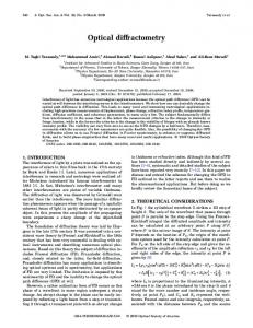
could occur during the measurement of an essentially unchanged air-gap cavity. Another signal demodulation method that has been used is the fast Fourier transform, which transforms the signal from a wavelength domain to a cavity thickness domain.5 This method is characterized by an ability to measure absolute cavity thickness; however, the resolution is much lower than for the wavelength tracking method. In this Letter we describe a more accurate model for single-mode f iber (SMF) EFPI sensors and, based on the model, we present a novel signal-processing method that is capable of providing both high sensitivity and absolute measurement of the cavity thickness with a large dynamic measurement range. A schematic of a SMF EFPI sensor system with an enlarged view of the sensor head is shown in Fig. 1. The step-index weakly guiding lead-in SMF has a core diameter of 2a and refractive indices n1 in the core and n2 in the cladding. The F-P cavity with air gap d is formed between end face R1 of the lead-in SMF and another ref lector, R2 . Because the ref lections at the air –glass interface are small, we ignore the multiref lections in the F-P cavity. Thus the total f ield ref lected back to the lead-in fiber may be expressed as the summation of E1 , the field that is due to the f irst ref lection at R1 , and E2 , the f ield contributed by the
Fig. 1. Schematic of a SMF EFPI sensor system. schematic of a SMF EFPI sensor head. © 2004 Optical Society of America
Inset,
August 1, 2004 / Vol. 29, No. 15 / OPTICS LETTERS
ref lection at R2 . For a SMF, E1 may be assumed to be approximately Gaussian in shape, given by6 E1 苷 fe1 苷 E exp共2r 2 兾w0 2 兲 ,
(1)
where fe1 is the complex envelope of the f ield, E is the field amplitude, and w0 is the mode field’s radius. With this assumption, the complex envelope of the f ield that emanates from the lead-in f iber and is ref lected back to R1 after propagating a length 2d in the free space inside the F-P cavity may be expressed as7 fe2 苷 E共 jk0w0 2 兾2q兲exp共2jk0 r 2 兾2q兲 ,
(2)
where q 苷 2d 1 jk0 w0 2 兾2 is the q parameter of the Gaussian beam, k0 苷 2p兾l is the propagation constant, and l is the optical wavelength. Field fe2 is then coupled to E2 , which may be expressed as E2 苷 hfe1 exp共 jk0 2d 1 j p兲 苷 jhjEfe1 exp共 j 4pd兾l 1 jp 1 ju兲 ,
(3)
where h is the mode-coupling coefficient from fe1 to fe2 , which one may obtain by performing the overlap integral of fe1 and fe2 over surface R1 (Ref. 8): h 苷 jhjexp共 ju兲
RR
ⴱ R1 fe1 fe2 dxdy . RR 苷 RR 共 R1 fe1 ⴱ fe1 dxdy R1 fe2ⴱ fe2dxdy兲1兾2
(4)
In Eq. (3), phase shift p arises from the ref lection at R2 of light incident from a medium that is optically less dense to a medium that is optically denser. Thus the interference signal can be expressed as I 共l, d兲 苷 共E1 1 E2 兲 共E1 1 E2 兲ⴱ ~ I0 共l兲R关1 1 jhjcos共4pd兾l 1 p 1 u兲兴 ,
(5)
where I0 共l兲 is the light source’s power spectrum, which is assumed to be known, and R is a constant associated with the transmission loss of the f iber and ref lection loss at the two f iber ends. The normalized spectrum fringe Inorm 共l, d兲, which is normalized by I0 共l兲, may then be expressed as Inorm 共l, d兲 苷 A 1 B cos共4pd兾l 1 p 1 u兲 ,
1737
and n2 苷 1.444 at a wavelength l 苷 1550 nm. The phase shift increases from 0 to 0.358p when the air gap is changed from 0 to 100 mm. Provided that the spectrometer is calibrated, normalized fringe spectrum I 0 共l兲 obtained as a function of wavelength l is known. One can obtain air gap d by fitting Eq. (6) to I 0 共l兲, using fitting parameters A, B, and d. However, in practice, the perturbations of environment and the fabrication of a SMF EFPI sensor could introduce bendings in the fiber, i.e., when the lead-in fiber is fused welded to the glass tube9; and it is well known that the bending loss of a SMF is a function of optical wavelength.10,11 Furthermore, predicted coupling phase shift u may depart slightly from its true value because of imperfections of the sensor head and calculation errors. Instead of Eq. (6), we use Inorm 共l, d兲 苷 关A 1 B cos共4pd兾l 1 p 1 u兲兴 共C兾l 1 D兲 (7) to fit I 0共l兲, in which constants A, B, C, and D and air gap d are the fitting parameters. In Eq. (7) the linear function of wave number 1兾l, C兾l 1 D, is used to model the bending losses of the f iber as a function of wave number. Furthermore, by adding the linear function in Eq. (7) we can adjust the phase of the f itted curve to its theoretical result in the f itting process when the theoretical phase shift is close to its true value. A least-squares f itting approach is used, which makes variance S a minimum: S苷
Z 1/l
关I 0共l, d兲 2 Inorm 共l, d兲兴2 d共1兾l兲 .
(8)
This signal-processing algorithm for SMF EFPI sensors was experimentally investigated with the help of the optical setup shown in Fig. 1 and the optical sensor shown in Fig. 3. We fabricated the sensor by inserting two 125-mm-diameter Corning SMF-28 SMFs (the lead-in f iber and the target fiber) with cleaved ends into a hollow glass tube to which the target fiber was bonded with epoxy. The lead-in f iber was bonded to a one-dimensional translation stage by which the air gap of the F-P cavity could be adjusted over a large spatial range. The hollow tube with an inner diameter of 132 mm facilitated alignment of the two fiber
(6)
where A and B are two constants. From Eq. (6), the fringe phase comprises three terms: The f irst term is the air-gap related phase shift, the second is the p phase shift that arises from the ref lection at R2 , and the third term is the u phase shift that is due to the coupling from fe1 to fe2 , which has not been addressed by many authors.3,6 Figure 2 shows the calculated coupling-induced phase shift u as a function of air gap d for a SMF with a 苷 4.5 mm, n1 苷 1.448,
Fig. 2. Calculated coupling phase shift u as a function of air gap d at wavelength l 苷 1550 nm. The parameters used for the SMF were a 苷 4.5 mm, n1 苷 1.448, and n2 苷 1.444.
1738
OPTICS LETTERS / Vol. 29, No. 15 / August 1, 2004
Fig. 3. Construction of the SMF EFPI sensor used in the test.
Fig. 4. Result of evaluation of the sensor’s air gap at 10 air-gap levels.
This effect is magnified in Fig. 5, where the air gap that corresponds to the measurement numbers from 103 to 156 is displayed. The points correspond to the third step shown in Fig. 4. The drift of the mechanical translation stage is clearly evident in Fig. 5, in which the solid line that represents the least-squares linear fit of the measurement of the air gap as a function of the measurement number. The f luctuation of the measured points about the best-fit line through the data can be taken as a measure of the standard deviation of the algorithm. It is possible that some of the variation about the line is due to the mechanical translation stage as well. The standard deviation of the f itting error represents the variation that is due to all sources of error including the algorithm, and it is calculated to be 0.288 nm, which can be taken as a worst-case estimate of the resolution of the algorithm. In conclusion, we have presented and experimentally verified a novel signal-processing algorithm for a single-mode optical f iber extrinsic Fabry – Perot interferometric sensor. By obtaining the exact expressions of the fringe phase as a function of the air gap from the model of the single-mode optical fiber EFPI sensors, this method achieves high-resolution, absolute measurement of the air gap while at the same time it allows for a large dynamic measurement range. The measurement accuracy depends on the accuracy of the model. Errors might be introduced by various imperfections of the sensor, such as nonparallelism of the two f iber ends. The model assumes that the spectrum fringe is a cosine function with a linear amplitude modulation as a function of the wave number; however, more-complex modulations of the fringe envelope owing to bending losses of the single-mode fiber may cause the f itting process to converge to an erroneous air-gap value. This error could be compensated for by use of a higher-order polynomial to f it the envelope modulations. M. Han’s e-mail address is
[email protected].
Fig. 5. Enlarged view of the evaluation result for the third air-gap level measurement and its linear fitting as the measurement number.
tips and protected the F-P cavity from environmental perturbations. A high-resolution swept laser interrogator (HR-SLI; V5.1; MicroOptics, Inc.) functioned both as a whitelight source and as a spectrometer. The spectral intensity was sampled from 1520 to 1570 nm; the total number of samples was N 苷 2000 at equal wavelength intervals of 0.025 nm. During the measurement we increased the air gap from 55.0 to 62.3 mm in ten steps by adjusting the translation stage, and at each step the spectrum was sampled for roughly 2 min at a sample rate of 0.5 Hz. The total air-gap change was 7.3 mm, and the result of the measured air gap is shown in Fig. 4, which indicates that the air gap was increased slightly at each level owing to the mechanical drift of the translation stage after the air gap was adjusted.
References 1. T. Li, R. G. May, A. Wang, and R. O. Claus, Appl. Opt. 36, 8858 (1997). 2. L. B. Yuan, L. M. Zhou, W. Jin, and C. C. Chan, Rev. Sci. Instrum. 71, 4648 (2000). 3. V. Bhatia, M. B. Sen, K. A. Murphy, and R. O. Claus, Electron. Lett. 32, 247 (1996). 4. B. Qi, G. R. Pickwell, J. Xu, P. Zhang, Y. Duan, W. Peng, Z. Huang, W. Huo, H. Xiao, R. G. May, and A. Wang, Opt. Eng. 42, 3165 (2003). 5. W. Pulliam, P. Russler, R. Mlcak, K. Murphy, and C. Kozikowski, Proc. SPIE 4202, 21 (2000). 6. V. Arya, M. de Vries, K. A. Murphy, A. Wang, and R. O. Claus, Opt. Fiber Technol. 1, 380 (1995). 7. P. P. Banerjee and T.-C. Poon, Principles of Applied Optics (Irwin, Homewood, Ill., 1991). 8. C. M. Miller, S. C. Mettler, and I. A. White, Optical Fiber Splices and Connectors: Theory and Methods (Marcel Dekker, New York, 1986). 9. G. Belleville and G. Duplain, Opt. Lett. 18, 78 (1993). 10. D. Marcuse, Appl. Opt. 23, 1082 (1984). 11. A. Bjarklev, J. Lightwave Technol. 4, 341 (1986).