Abstract â This paper presents simplified fuzzy logic speed control (FLSC) for vector controlled permanent magnet synchronous motor (PMSM) drives. The fuzzy ...
International Review of Electrical Engineering (I.R.E.E.), Vol. xx, n. x
Simplified Fuzzy Logic Speed Controller for Vector Controlled Permanent Magnet Synchronous Motor Drives Zulkifilie Ibrahim1, Siti Noormiza Mat Isa2, Jurifa Mat Lazi3, Md Hairul Nizam Talib 4 Abstract – This paper presents simplified fuzzy logic speed control (FLSC) for vector controlled permanent magnet synchronous motor (PMSM) drives. The fuzzy logic controller is a multi-parameter controller where the performance depends upon the chosen shape of membership function (MF), rule base and scaling factor. In this paper, rule base is viewed as a control strategy to design the simplified FLSC. The FLSC simplification is designed by rule base simplification through two diferrent approaches. The first approach implements the rule simplification by reducing the number of MF used and adjusting the arrangement of chosen MFs for each fuzzy variable. The second approach obtains the rule simplification by eliminating the rules that are infrequently fired by the PMSM drives while maintaining the dominant rules. In doing so, the standard 49 rules is simplified become 9 rules by first approach while the other approach produces 7 rules. The efficacies of the FLSC simplifications are investigated based on comparative studies of speed performances with the standard FLSC which consisting of 49 rules. The standard FLSC is designed based on common criteria from numerous literatures. The mathematical model of the PMSM drive system is simulated in MATLAB environment with Simulink and Fuzzy Logic Toolbox. The simulation results are validated with the experimental results for various operating conditions, load disturbances and inertia variations. The simulation and experimental results showed that the simplified FLSCs obtain nearly equivalent performance with the standard FLSC, thus indicating the effectiveness of the rule simplification. Copyright © 2009 Praise Worthy Prize S.r.l. - All rights reserved.
Keywords:
Simplified Fuzzy Logic Speed Controller, Rule Simplification, Vector Control, Permanent Magnet Synchronous Motor
Nomenclature �� �� , �� ��� , ��� � ��, ��� �� , ��
� � , � � , �� � , �� , �� ��� � �� , ��� , ��� � � �� ��
Stator resistance d- and q-axis magnetizing inductances d- and q-axis stator voltages d- and q-axis stator currents d- and q-axis stator flux linkages Stator flux linkage Rotor angular position Rotor angular speed Three phase stator currents Inverter voltages Dc link voltage Switching function Error, change in error and output scaling factor Total inertia Number of pole pairs Electromagnetic torque Load torque
I.
Introduction
Fuzzy logic controller (FLC) is well-known with its potential to obtain superior speed control in high performance drives (HPD). It has been proven by numerous publications through simulation and experimental verifications including DC motor [1], induction motors [2-4], permanent magnet synchronous motors [5-7], brushless DC motor [8] and others. The FLC allows the designer to control a complex plant system especially a nonlinear and ill-defined plant model. For example, dynamic d-q model of an AC machine is a multivariable, complex and nonlinear model. Although vector control could overcome this problem, but the accurate vector control is impossible to model since there are wide parameter variations [9]. However, the FLC able to address this problem by not require an exact mathematical model besides it can be determined by the operator’s experience and heuristic.
Manuscript received January 2007, revised January 2007
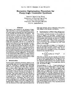
On the other hand, the FLC is a multi-parameter controller whereby the performance depends on the selected shape of membership function, rule base and scaling factor [10]. In this paper, the control strategy of the FLC is isolated in a rule base opposed to the mathematical equation. Reference [11] reported that all fuzzy rules contribute to some degree to the final inference or decision, however, some rules fired weakly do not contribute significantly to the final decision and may be eliminated. The extension of that, a study on rule base used is investigated for this research. The rule base must be obtained carefully to obtain the relation between input and output of the system. The number of rules used is not limited and it depends on the application. Numerous literatures presented vector controlled PMSM drives with a variety of rule sets. The common rule set consisting of 49 rules which are produced by seven MFs for each input variable [12]-[13]. Meanwhile, several implementations of FLC based on 25 rules [14], 20 rules [15] and 15 rules [16]. Besides that, the effect on the number of rules used is investigated to a PMDC motor drives [17]. Three different rule sets consisting of 49 rules, 25 rules and 9 rules are produced. The triangular and trapezoidal types of MF are utilized. The type and arrangement of MFs are similar for all rule sets. The results indicated that the rule variations give significant effect on the FLC output but a little effect on the motor drives output. This concluded that the number of rules does not give major impact to the system performance as long as they express similar relationship in terms of MF shape. The characteristics of rule base is discussed by Zheng [18] and Ibrahim [19]. Consider standard rule set consists of 49 rules is illustrated in Fig. 1. The rule table is categorized into five zones. Each zone has specific function where zone 1 affects the stability of the whole control system. Zone 2 and 4 will effect to the responsiveness of the control system. Meanwhile, the rules in zone 3 and 5 are infrequently fired by the system. Therefore, the zone 1, 2 and 4 are more important than the rules that located in zone 3 and 5. Besides that, Fig. 1 also shows the trajectory of fired rule base which is represented by the arrow. The route is constantly moves towards the stable point where both error and change of error are zero [18]. The fired rules pass through every zones and move towards zone 1 where stable point is located. Moreover, the shorter route produces more stability to the system. This means that the rule base should be reduced in order to produce the shorter route.
Copyright © 2007 Praise Worthy Prize S.r.l. - All rights reserved
Z. Ibrahim, S. N. Mat Isa, J. Mat Lazi, M. H. N. Talib
simulation study based on following modeling equations.
III.1.
Fig. 1. Zones and shifting route of rule base in a rule table This paper attempts to design a simplification on rule base used for the vector controlled PMSM drives. The Standard FLSC is determined based on common criteria from numerous publications. It consists of 49 rules which are produced by seven MFs for two input variables (7x7=49 rules). The trapezoidal and triangular MFs are utilized with uniform size. Two simplified FLSCs are designed based on different approaches which are Simplified 9-rules FLSC and Simplified 7-rules FLSC. In order to make a fair comparison, the similar PMSM drives model is being used for these standard and simplified FLSCs. Vector control technique was introduced in 1972 [20]. This control technique shows that decoupled control of flux and torque is compatible with the three-phase AC drives whereby the performance can be equivalent to the DC drives [21]-[22]. The PMSM is highly desirable capabilities of a separately excited DC motor while retaining the general advantages of the AC motor. It offers precise, robustness in rotor construction, small size, fast dynamic response, easy maintenance, high torque, high power and low noise because of the permanent magnets placed in the rotor develop air gap magnetic flux without any external excitation [9].
II.
PMSM Drive System
A structure of FLSC for a vector controlled PMSM drive is illustrated as Fig. 2. Data of the motor used are given in Table I. The drives consist of FLC, hysteresis current controller (HCC), voltage source inverter (VSI) and PMSM. The actual rotor speed � is compared with reference speed �∗ and the resulting error is processed ∗ in the FLC. The output of FLSC is q-axis reference current ��� . ∗ Meanwhile, d-axis reference current, � �� is considered as zero. Both daxis and q-axis stator currents generate three phase reference currents (� ∗ , ��∗ , � �∗) through Park’s transformation. The reference currents are sinusoidal wave in phases which are compared with sensed winding currents (� , �� , � � ). Then, the resulting current errors are fed to HCC to generate switching signals (� , �� , �� ) for the VSI. Thus, by obtaining the winding currents of the system, the speed can be obtained. iqs* * Sabc iabc ωr*
ωr
ids* = 0
Modeling of PMSM
The mathematical model of PMSM is initially derived from the synchronous motor under assumptions of saturation is neglected although it can be taken into account by parameter changes, the induced EMF is sinusoidal, eddy currents and hysteresis losses are negligible, no field current dynamics and no cage on the rotor [23]. The stator voltage equations in the rotor reference frame are given by: � �� (1) ��� = �� � �� + − � �� �� � �� (2) ��� = �� � �� + + � �� �� where flux linkage are ( �� = �� ��� + ) and ( = �� � �� ). ��� and ��� are d,q axis stator voltages, ��� and ��� are the d,q axis stator currents. �� and �� are the d,q axis inductances. is the stator flux linkage produced by permanent magnets. �� is stator-winding resistance per phase. � is rotor speed in rad/sec (electrical).All the parameters of PMSM are given in Table I. The developed electromagnetic torque expression is: 3 (3) �� = �[ ��� + (�� − �� )��� ���] 2 where � is the number of pole pairs. ��� is equals to zero as the PMSM do not need excitation current to the stator winding because of the flux in the motor is already provided by magnets that attached at the rotor. The d-axis magnetizing inductance is equals to the q-axis magnetizing inductance (�� = �� ) since the saliency effects is neglected due to large effective air gap is developed in the case where the magnet bars are mounted on the rotor surface [24]. Both d- and q-axes inductances are represented by �� . This yields torque as: 3 (4) �� = � ��� 2 The electromagnetic torque is balanced by the load torque and accelerating torque of the system and can be defined in electromechanical equation as: � � (5) �� = �� + � �� where �� is load torque and � is the moment of inertia. For dynamic simulation, the d-q model equations of PMSM must be expressed in the form of first order differential equations as: ���� 1 = (��� − �� � �� + �� ���) (6) �� �� ���� 1 = (��� − �� � �� − �� � �� − ) (7) �� �� � � 1 = (�� − �� ) (8) �� � ��� (9) = � �� where �� is the position angle of the rotor. ��� and ��� are the forcing function to decide the currents in d-q model which may be obtained from three phase voltages (� , �� , �� ) through Park’s Transformation as: 2 2. 4. (10) ��� = [� '()� + �� cos -� − / + �� cos(� − )] 3 3 3 2 2. 4. (11) ��� = − [� )�1� + �� sin -� − / + �� )�1(� − )] 3 3 3 where � , �� , �� are the instantaneous phase voltages impressed across phase windings and are decided by the inverter.
iabc
III.2. Fig. 2. FLSC for vector controlled PMSM drives
III. Modeling of FLSC for Vector Controlled PMSM Drives Fig. 2 shows the components used for implementing the FLSC to the vector controlled PMSM drives. Firstly, each block is modeled for Copyright © 2007 Praise Worthy Prize S.r.l. - All rights reserved
Vector Control of PMSM
The three phase reference stator currents are computed using inverse Park’s Transformation of reference d-q stator currents as: ∗ ∗ � ∗ = ��� '()� − ��� )�1� (12) 2. 2. ∗ ∗ ∗ (13) �� = ��� cos -� − / − ��� sin(� − ) 3 3 4. 4. ∗ ∗ (14) ��∗ = ��� cos -� − / − ��� sin(� − ) 3 3
International Review of Electrical Engineering, Vol. xx, n. x
Z. Ibrahim, S. N. Mat Isa, J. Mat Lazi, M. H. N. Talib
III.3.
Source Inverter and Hysteresis Current Controller
The three phase voltage source inverter (VSI) is modeled by insulated gate bipolar transistor (IGBT) in order to provide fast switching frequency. The current controller is used to switch the appropriate IGBT by ensuring the motor current can follow the command current as accurately as possible. The current-controlled VSI is usually utilized in vector controlled high performance drives because of quick response and accurate control [25]. The hysteresis current controller is used to provide pulse width modulated signal (switching signal). Assume the switching functions of the three inverter legs be represented as � , �� , �� . The inverter voltages can be given by following equations: ��� (15) � = (2� − �� − �� ) 3 ��� (16) �� = (2�� − �� − � ) 3 ��� (17) �� = (2�� − � − �� ) 3 III.4.
Fuzzy Logic Speed Controller
The precise control of speed and position makes the system insensitivity to the disturbances and parameter variations. In doing so, a proper design for feedback control is obtained. The electrical speed of rotation is obtained by using mechanical motion of the motor model as Equation (5) and yields following equation: 1 � = 4 [�� − �� ] (18) � 67 where the mechanical speed in rad/sec (mechanical) is 5 = . � is 8
the number of pole pairs. The rotor angular position is: �� = 4 � ��
Ge
ce
Gce
E CE
Fuzzy Logic Controller
CU
Gcu
cu
Fig. 3. Fuzzy logic control with scaling factors input Fuzzification
Rule Evaluation
Fig. 5.
(19)
Fuzzy logic is used to control speed of vector controlled PMSM drives. In particular, the FLC used to generate change in torque current ∗ with two input variables which command (q-axis stator current) ∆� �� are speed error and change in speed error: :(;) = �∗ (;) − � (;) (20) ':(;) = :(;) − :(; − 1) (21) where :(; − 1) is the error from previous sampling. The actual value of the FLC output is obtained by ∗ (;) ∗ (; ∗ ��� = � �� − 1) + ∆� �� (;) (22) The structure of FLSC is illustrated as Fig. 3. There are two inputs which are speed error, : and change in speed error, ':. The output is ∗ change in q-axis reference current, ∆��� represented by '