Tomasz Czajkowski, Ian Kuon, Peter Jamieson, and the anonymous reviewers for their many helpful comments and suggestions. Finally, thanks to CMC/SOCRN ...
Simplifying the Integration of Processing Elements in Computing Systems using a Programmable Controller Lesley Shannon and Paul Chow Department of Electrical and Computer Engineering University of Toronto Toronto, ON, Canada M5S 3G4 {lesley, pc}@eecg.toronto.edu
ABSTRACT As technology sizes decrease and die area increases, designers are creating increasingly complex computing systems using FPGAs. To reduce design time for new products, the reuse of previously designed Intellectual Property (IP) cores is essential. However, since no universally accepted interface standards exist for IP cores, there is often a certain amount of redesign necessary before they are incorporated into the new system. Furthermore, the core’s functionality may need updating to support the requirements of the new application. This paper demonstrates how the SIMPPL system model allows designers to rapidly implement on-chip systems comprising multiple Computing Elements (CEs). Furthermore, using a controller-based interface to manage inter-CE transfers enables users to easily adapt the control sequence of individual CEs to suit the needs of new applications without necessitating the redesign of other elements in the system. Two systems using three different hardware modules adapted to CEs are described to illustrate the power and simplicity of the SIMPPL model. It required a total of six hours to implement both designs on-chip once the individual CEs had been designed.
1.
INTRODUCTION
Commercial Field Programmable Gate Arrays (FPGAs) are now large enough to support designs comprising multiple processors and dedicated hardware modules. To minimize the design time for such complex circuits, designers try to reuse previously designed modules, known as Intellectual Property (IP) cores. For example, an MPEG-4 design uses cores such as the DCT, IDCT, and Frame Store (memory) that are common to other multimedia applications. While this system may be viewed as dedicated hardware, it can also be thought of as a computing system that uses direct communication between different types of Processing Elements (PEs), as shown in Figure 1 [1]. The goal of achieving the rapid development of custom computing systems requires that low-level hardware design be minimized. Integrating PEs at the physical level necessitates the development of a hardware interface that provides synchronization, control, and data transfer between cores. Synchronization supplies the handshaking needed to indicate when there is a valid data transfer and the control signals direct the operations to be performed and report the current status of the core. Finally, the data transferred between cores must be in the required format and sequence to be correctly
+
DCT
_
Q Q
-1
motion texture coding
video multiplex
IDCT + +
S w i t c h
pred. 1 pred. 2
Frame Store
pred. 3
Motion estimation Shape coding
Figure 1: Block diagram of the possible PEs in an MPEG4 encoder. interpreted by the receiving cores. To simplify the physical level connections (physical interface) between PEs, a standardized hardware interface and communication structure is required. Currently, IP cores are connected together using direct communication, often implemented as random glue logic, or by adapting the cores to a common standard, such as a bus. However, designs that pass data from one module to the next, as in Figure 3, typically use a direct communication structure. Previous work introduced the need for standardizing the physical interconnect between system modules so that the user can abstract the physical design information from the data transferred between modules [2]. Modelling designs as Systems Integrating Modules with Predefined Physical Links (SIMPPL) allows each module to represent a dedicated hardware or processor-based (software) Computing Element (CE) that connects to other CEs via fixed communication links. A CE combines a PE, an IP core that performs some given function, with the control sequence that dictates how the PE is used by the rest of the system. Since the communication links are fixed in the SIMPPL model, the actual physical interfacing of CEs is a trivial problem. With a fixed physical interface, the mechanism for the physical transfer of data across a link is provided so that the designer can focus on the meaning of the data transfers, rather than how to connect the wires. This is similar to the software world where, when using procedures, a programmer is never concerned with the use of the stack or the format of the stack frame for the specific implementa-
H/W IP to OCP
H/W IP to OCP
OCP to Bus A
OCP to Bus B
Bus A
Bus B
IP Interface
H/W IP
(a)
H/W IP
(b)
Figure 2: Standardizing the IP interface using (a) OCP for different bus standards and (b) SIMMPL for point-to-point communications. tion platform. Using a standard hardware interface enables hardware designers to similarly concentrate on adapting the application-specific control sequence of each CE to the new application. This paper discusses the details of the SIMPPL model and describes how to adapt different IP cores to programmable hardware CEs. Each core has a controller that generates and interprets the communication protocols for internal links. The sequence of operations performed by the controller is dictated by a program and the requests received over the input links. Thus, the designer can change the control sequence of any CE in the system simply by changing the program run by its controller. This is demonstrated using three hardware CEs to create two variations of a system on-chip in only six hours. The remainder of this paper is structured as follows. Section 2 provides an overview of communication and IP core standards along with a summary of the SIMPPL model at the system level followed by Section 3, which describes the details of the SIMPPL controller for hardware CEs. The implementation of three different types of IP cores using this controller is outlined in Section 4 and Section 5 describes the platform-specific implementation details for the systems using these cores. Finally, Section 6 concludes the paper along with providing suggestions for future work.
2.
BACKGROUND
The following is a discussion of some previous work investigating on-chip interconnect structures and methods of simplifying IP reuse. The section closes with a system-level description of the SIMPPL system architecture.
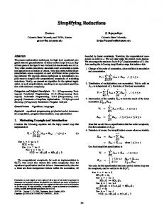
2.1 IP Reuse Multiple books exist discussing the complexities involved in reusing legacy IP in new designs [3, 4]. The challenges of using IP to reduce design time due to problems that arise when incorporating previously designed modules into new designs are of significant concern. This has led to the development of well-defined IP design methodologies [5, 6] to ensure reusability of cores with fixed interfaces and fixed functionality. It does not, however, address the common situation where a module has defined functionality but requires the ability to interface with different communication structures. The VSI Alliance has proposed the Open Core Protocol (OCP) [7] to enable the separation of external core communications from the IP core’s functionality, similar to the SIMMPL model. Both communication models are illustrated in Figure 2. OCP is used to provide a well-defined socket interface for IP that allows the designer to easily attach fixed interface modules that support different bus stan-
dards. This allows a designer to easily connect a core to all bus types supported by the standard. In contrast, the SIMPPL model targets the direct communication model using a fixed, point-to-point interconnect structure for all onchip communications. More recently an Interface Adaptor Logic layer has been proposed [8]. It is very similar to the OCP, using a fixed socket interface for IP modules, however unlike OCP, it is aimed at IP reuse in reconfigurable SoCs. FPGA companies also recognize the importance of simplifying the inclusion of previously designed IP into newer system designs. Xilinx even provides its own bus-interface module for IP with a defined socket interface [9]. These protocols make it easier to port IP among different bus standards, whereas SIMPPL addresses the problems of adapting an IP core’s functionality to the requirements of a new application.
2.2 On-Chip Communication Structures Multiple different on-chip interconnect strategies have been proposed for SoC design, including hierarchical buses that use bridges to connect to each other [10, 11, 12]. These bus structures can all be mapped to an FPGA, but the maximum bandwidth for each bus is limited by the number of modules connected to it. The WISHBONE [13] SoC Interconnect architecture provides multiple different interconnect structures that can also be mapped to an FPGA, thereby allowing the designer to select the bus architecture for a particular system. Since all are designed as single-level buses, the standard provides the user with a simpler design approach, unless components running at different clock rates must share the same bus. Berkeley’s SCORE [14] architecture divides system computations into fixed-size pages and uses the data abstraction of streams to pass data between pages. Streams provide a high-level description of point-to-point communication, comparable to the SIMPPL internal communication link, without defining a physical connection. Adaptive Systemon-chip (aSOC) [15] uses a physical implementation of a point-to-point communication architecture for heterogeneous systems, where unlike the SIMPPL model, the communication interface for each module is tailored in hardware to optimize the module’s performance. Networks provide another form of on-chip communication. MicroNetwork [16] has a pipelined data network to communicate between modules. It also includes the previously described OCP socket as an interface for the heterogeneous system modules and rotates the communications resources among the inter-module transfer requests. A Stanford project on scalable network fabrics [17] also uses a common network for passing data between modules. The system is partitioned into tiled modules and the routing network is associated with the tiles such that packets are rerouted at each tile. This idea of using data packets is similar to the data-passing method used in the SIMPPL model, but the lack of flexibility in a predefined placement and structured network architecture is not as suitable to SoC designs on FPGAs as the point-to-point communications of the SIMPPL model.
2.3 SIMPPL Computing System Model Figure 3 illustrates the previously proposed macro-level description of a system built using the SIMPPL architectural model [2]. The solid arrows indicate internal links and the dotted arrows indicate I/O communication links to ex-
off-chip c
SIMPPL Controller
on-chip
Internal Rx Link
CE
CE
CE c
CE
CE
c
c
Figure 3: A generic computing system described using the SIMPPL model. Rx Tx
I R
Prog Instr SIMPPL Control Sequencer (SCS)
CE
E X
a0
Controller Status Bits
R E G
Internal Rx and Tx Communication Links (FIFOs)
SIMPPL Controller PE (Hardware IP)
SIMPPL Control Sequencer (SCS)
Computing Element (CE)
Received Data
Internal Tx Link
Optional Asynchronous FIFOs
Transmitted Data
External I/O Signals
Processing Element (Hardware IP)
Figure 4: The internal structure of a hardware CE. ternal devices. The I/O communication links and protocols between a CE and an off-chip device are determined by the off-chip device, however, the internal communication links are fixed and the communication protocols between modules are abstracted from the physical links and may be adapted to the requirements of each CE. An n-bit wide asynchronous FIFO is used as the standard internal link for this investigation of the SIMPPL model. Asynchronous FIFOs provide clocking flexibility to system designers as they allow CEs to send and transmit data at independent data rates. This decouples the CE’s inter-module communications from processing, thereby allowing independent clock domains for individual CEs without complicating the system level design. Since the number and type of data words transmitted or received by a CE is dependent on the nature of its computation, the width and depth of the FIFO can be altered to provide greater bandwidth and support data packets of varying lengths. To support the communication protocols described in the following section, the FIFO data-width is currently set to 33-bits but the depth is left variable.
3.
SIMPPL CONTROLLER
The SIMPPL controller architecture provides the physical interface to the IP core and supports an instruction set designed to facilitate reprogramming the core’s operations for different applications. For example, a CE that has an audio sampling PE can be reprogrammed to sample the signal received from an external audio device at different rates depending on the requirements of the computing system. Details and an example of how the controller supports reprogramming are given below.
3.1 Controller Architecture Figure 4 illustrates the main components of a hardware CE. The PE is used to perform a specific function, be it com-
Figure 5: An overview of the SIMPPL controller datapath architecture. putational or communication with an off-chip peripheral, and interacts with the rest of the system via the SIMPPL controller, which interfaces with the internal communication links. The SIMPPL Control Sequencer (SCS) module represents the separation of the controller functionality from communications enabled by the fixed interface and communication protocols. The SCS stores the program and supplies the sequence of instructions to be executed by the controller for each application. The instruction set supported by the SIMPPL controller is described in Section 3.2 and provides the flexibility required to adapt the CE to reflect the requirements of each application. The protocol used to communicate over the internal links requires that all transmissions must initiate with an instruction to indicate to the receiving controller how to process the received information. This condition enables a receiving CE to correctly interpret the data packets sent from transmitting CEs and satisfies the need for handshaking in inter-CE communications. Figure 5 illustrates the SIMPPL controller’s datapath architecture. The controller executes instructions received via both the internal receive (Rx) link and the SCS, where the Rx link instructions have higher priority than program instructions. This allows the controller to use handshaking with other CEs to dictate the instructions to be executed. Since the user must be able to properly order the arrival of instructions to the controller from two sources, allowing multiple instructions in the execution pipeline greatly complicates the synchronization required to ensure that the correct execution order is achieved. Therefore, the SIMPPL controller is designed as a single-issue architecture, where only one instruction is in flight at a time, to reduce design complexity and to simplify program writing for the user. The SIMPPL controller also provides status bits that can be used by the SCS to determine if the program should
Instruction Type
Rx CE
1 Num Data Words (NDW) 0
Immediate Address
0
Data 0
0
Data 1
0
Data 2
opcode } Instruction
. . .
0
Data NDW - 1
control bit
program word
} Optional
Data Packet
Tx CE
Figure 6: An internal link’s data packet format. branch. The status bits are PE specific and are generated based on the PE’s runtime status to better aid in the control of program execution order. The format of an output data packet sent via the internal transmit (Tx) link is dictated by the instruction currently being executed. The inputs multiplexed to the Tx link are the instruction, the immediate address that is part of some instructions, the address stored in the address register a0 and any data that the hardware IP transmits. Data can only be received and transmitted via the internal links and cannot originate in a controller’s program. Furthermore, the controller can only send and receive discrete packets of data, which may not be sufficient for certain types of PEs requiring continuous data streaming. To solve this problem, the controller supports the use of optional asynchronous FIFOs to buffer the data transmissions between the controller and the PE. The designer can then clock the controller at a faster rate than the PE to guarantee that it accurately receives/produces at the necessary data rate.
3.2 Controller Instruction Set While the current SIMPPL controller uses a 33-bit wide FIFO, the data word is only 32-bits. The remaining bit is used to indicate whether the transmitted word is an instruction or data. This is shown in Figure 6, which provides a description of the generic data packet structure transmitted over an internal link. The instruction word is divided into the least significant byte, which is designated for the opcode, and the upper 3 bytes, which represents the Number of Data Words (NDW) sent or received in a data transmission instruction. The current instruction set uses only the five Least Significant Bits (LSBs) to represent the opcode. All SIMPPL controller instructions require at most two words – the instruction word and an optional immediate address data word. The instruction set is divided into two groups, instructions that perform a control operation and those that transfer data. Instructions resulting in data transfers are further subdivided into three different categories. The first is the read request. It is issued by the program of one CE and sent to another CE requesting that data be transmitted back
Imm. Data Transfer Imm. Data + Imm. Addr. Addr. Reg. Initialization Addr. Reg. Arithmetic Imm. Data + Indir. Addr. Imm. Data + Autoinc. Wait Receive No-op Reset
Rd
Wr
Rx
X X
X X X X X X
X X
X X
X X
Issue Instr P/R P/R P P P P P P P
Exec. Instr P/R P/R P P P P P R R
Table 1: The current instruction set supported by the SIMPPL controller. to the original CE. Secondly, a receive instruction must be generated as the first transmitted word to accompany the data sent back to the first CE, since all transfers via internal links start with an instruction. Finally, the program can use a data write to accompany data words transmitted to another CE. Table 1 lists all the instructions currently supported by the SIMPPL controller. The objective is to provide a minimal instruction set, to reduce the size of the controller, that still provides sufficient programmability such that the cores are easily reconfigured for any potential application. While instructions that are needed to fully support the reconfigurability of some types of hardware may be missing, the instructions in Table 1 support the hardware CEs that have been built to date. Furthermore, the controller supports the expansion of the instruction set to meet future requirements. The first column in Table 1 describes the operation being performed by the instruction. Columns two through four are used to indicate whether the different instruction types can be used to request data (Rd), write data (Wr), or receive data (Rx). Finally, the last two columns are used to denote whether the instruction may be issued or executed from the Program memory (P) or internal receive communication link (R). The first instruction type described in Table 1 is the immediate data transfer instruction. It consists of one instruction word of the format shown in Figure 6, where the two LSBs of the opcode indicates whether the data transfer is a read request, a write, or a receive. Similar to the immediate data transfer instruction is the immediate data plus immediate address instruction. The format is the same as the former instruction except that an additional data word is required as part of the instruction to indicate the address. Instructions that use the a0 register may have a one or two-word format, but are not transmitted as they only make sense in the context of the local controller. For instance, a two-word instruction initializes the local address register with an immediate value, the first contains the opcode and the second is the new address. The address register arithmetic instructions are single word instructions used to add or subtract an offset to the current local address register value. The value in the address register can provide the immediate address for any data transfer instructions sent to other CEs, using indirect addressing or indirect addressing with post-autoincrementing. The remaining instructions provide control functionality for the controller. The wait receive combined with the noop instructions can be used to provide handshaking controls between CEs. For example, one controller can execute the
SIMPPL Control Sequencer (SCS) Store Unit (Program)
Program Control Bit
Program Word
PC
Valid Instruction
Program Instruction Read
Status Bits
SIMPPL Controller
Figure 7: The standard SIMPPL control sequencer structure and interface to the SIMPPL controller. wait instruction, which stalls the controller until an instruction is received via an internal link. When the instruction is received, the wait will be cleared and the received instruction will then execute on the controller. In the case where the user desires no operation to be performed, except the termination of the wait instruction, a no-op should be used. Finally, the reset instruction can be used to clear all the status signals and registers for the controller.
3.3 SIMPPL Control Sequencer The operation of a SIMPPL controller is analogous to a generic processor, where the controller’s instruction set is akin to assembly language. For a processor, programs consist of the series of instructions used to perform the designed operations. Execution order is dictated by the processor’s Program Counter (PC), which commissions the next instruction of the program to be fetched from memory. While a SIMPPL controller and program perform the equivalent operations to a program running on a generic processor, the controller uses a remote PC in the SCS to select the next instruction to be fetched. Figure 7 illustrates the SCS structure and its interface with the SIMPPL controller via five standardized signals. The 32-bit program word and the program control bit, used to indicate if the program word is an instruction or address, are only valid when the valid instruction bit is high. The valid instruction signal is used in combination with the program instruction read to execute an instruction fetch. Finally, the controller provides a PE-specific set of status bits that are used by the PC to access the appropriate program instruction from the Store Unit, which acts like a memory. Since the PC has direct access to the control signals, branches can be implemented implicitly as transitions in a PC state machine. The PC state machine is applicationspecific and selects the correct values for the next instruction to be fetched from the store unit and sent to the controller depending on the current instruction and status bit values. This reduces the size of both the SIMPPL controller and the program located in the store unit by eliminating the need for branch instructions in the instruction set. Furthermore, it reduces the performance overhead of using a controller as an interface as it does not have to execute conditional or explicit branch instructions. The following example demonstrates how to write a program and use the SIMPPL controller interface.
3.4 Example SIMPPL Control Sequencer Assume a hardware system that consists of a memory and a sensor unit used to measure multiple environmental quantities at a set time interval. The total storage requirements
write start addr to a0; for (i=0; i< 1024; i++) { while (!valid_sensor_data); write 8 data words starting at addr (a0); a0 = a0 + 8; } Figure 8: Pseudocode for the sensor unit’s SIMPPL controller program. if (rst=1) { PCstate