Simulation-Based Lithography Optimization for Logic Circuits at 22nm and Below Michael C. Smayling
Valery Axelrad
Tela Innovations, Inc. 655 Campbell Technology Pkwy., Suite 150 Campbell, CA 95008 USA
[email protected]
Sequoia Design Systems, Inc. 137 Chapman Rd. Woodside, CA 94062 USA
[email protected]
Simulation has been an integral part of most of the techniques mentioned to push k1 lower. Model-based OPC relies on iterative layout modifications and close-loop simulations. OAI uses advanced illumination patterns to improve feature fidelity in specific cases. PSM have been used to improve contrast by providing a true zero-crossing of the electric field between pattern features. With continuing evolution of technology to higher numerical aperture (NA) optics, immersion, polarized illumination and overall low contrast at low k1, simulation has been forced to keep pace with technology or even be ahead of it to allow evaluation of future technology options.
Abstract—Lithography optimization based on physical simulation is a powerful technique to achieve good image quality at subwavelength feature sizes with small Rayleigh k1 factors. For the lower end of the 32nm logic node, even with immersion scanners, the Rayleigh k1 factor is below 0.32. The 22nm logic node should begin with minimum pitches of approximately 70nm, requiring some form of double patterning to maintain k1 above 0.25. For certain types of circuits such as NAND Flash, highly optimized scanner illuminators are well-known to improve feature fidelity. However, logic patterning has been more difficult than NAND Flash patterning because random logic was designed with complete “freedom” compared to the very regular patterns used in memory. Logic layouts with bends and multiple pitches resulted in larger rules, un-optimized illumination, and poorly understood process windows with little control of contextdependent “hot spots” [1].
All of the above mentioned techniques can be characterized as either process optimization (e.g. OAI) for a specific design (or design class), or design optimization (RET/OPC, PSM) for a specific process. Not surprisingly, process/lithography optimization can produce only limited results for unconstrained “free” logic designs, where many different layout element sizes, pitches and densities are present. Only when significant constraints are placed on the design is it possible to find a welldefined optimal set of lithography conditions.
The introduction of logic design styles which use strictly onedirectional lines for the critical levels now provides the opportunity for illumination optimization. Gridded Design Rules (GDR) have been demonstrated to give area-competitive layouts at existing 90, 65, and 45nm logic nodes while reducing CD variability [2, 3]. These benefits can be extended to ≤ 32nm logic using selective double pass patterning.
II.
Keywords: double patterning, gridded design rules, low k1, source-mask optimization
A. Strategy The starting point for new technology development is modeling and simulation based on experience from previous technology nodes [4]. This is often problematic since models for new equipment and processes are usually not available until well into the development project. Fortunately, for the foreseeable future, with λ/NA limited to 143nm, the available models are reasonably mature.
I. INTRODUCTION The past 50 years have been the era of continual improvement of photolithography resolution. This has allowed integrated circuit designs to shrink by more than a factor of one hundred. Prior to sub-100nm technology nodes, the exposure equipment resolution improvement trend kept the k1 value above 0.6, where k1 is the fitting factor in the Rayleigh equation CD = k1λ/NA. k1 has dropped below 0.6 for recent logic technology nodes. To maintain pattern fidelity at k1 values below ~0.6, resolution enhancement techniques (RET) such as optical proximity correction (OPC), off-axis illumination (OAI), phase shift masks (PSM), and double patterning have been introduced. It is expected that with the use of all of these techniques, immersion lithography at λ=193nm will be pushed to k1≈0.25
978-1-4244-3947-8/09/$25.00 ©2009 IEEE
LITHOGRAPHY SIMULATION
The linkage between layers in 1D GDR layout requires that those linked layers be co-optimized. Intra-layer constraints include optical resolution, photoresist thickness and optical properties, pattern complexity, device and electrical requirements, and CD variability requirements. Inter-layer constraints include alignment to perpendicular layers, alignment to the “hole” layers such as contacts or vias, and the pitches of perpendicular layers. Each layer may have a different solution based on the weighting of these factors.
111
The variables available for the optimization include lithography, mask, RET, circuit design, and potential process extensions. Lithography factors include wavelength, numerical aperture, illuminator, polarization, photoresist and resist processing, and anti-reflective coatings. Mask factors include phase shift options, mask materials, and mask writing/ inspection trade-offs. RET factors span several regimes, from mask data preparation such as OPC to illuminator conditions and mask type. Design factors include the layout style and the design purpose of different features. Process extensions such as self-aligned layers and spacer double patterning can dramatically shift the patterning burden from the exposure tool to other parts of the integrated process.
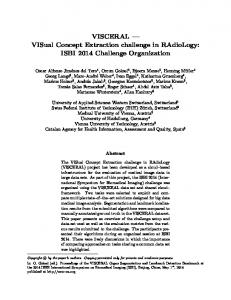
densities, and 3) bends in lines which cause necking and/or bridging “hot spots.”
B. Optimization Cost Functions Choosing an appropriate optimization cost function is obviously of crucial importance for meaningful optimization results. The choices range from getting specific CD values on target at nominal conditions to manufacturability metrics such as NILS (normalized image log slope), DOF (depth of focus) or even electrical performance metrics [5].
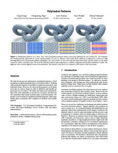
Fig. 2 shows how the pattern is split into two layout layers, the line pattern and the cut pattern. Creation of these patterns is straightforward for the 1D-GDR layout style shown in Fig. 1 on the right side.
Figure 1. Conventional 2D design style (left) and 1D-GDR (right) for the same circuit.
III. GRIDDED DESIGN RULES Source-mask-optimization (SMO) has been common for memory style layouts for many years, with more application to random logic in recent years. The problem with SMO for arbitrary 2D layouts has been that the solution either approaches a “lowest common denominator” with annular or at best quadrupole illumination, or the illuminator pattern becomes very complex and in some cases pixelated. Mask patterns based on an inverse transform method create patterns which may mathematically produce the desired aerial image but which may be costly to write and extremely difficult to inspect.
Figure 2. Line/cut double patterning for the gate layer.
The Gate “line” pattern is expected to have a width of 30nm and a space of 90nm at the 32nm node. This is a relatively relaxed pitch due to the Active contacts placed between the transistor gates. No OPC is required for the lines, although dummy lines at the edges of memory and logic blocks can be increased in width to avoid lifting lines, and the line pattern needs to extend past the blocks slightly to accommodate endof-line pullback.
By including design factors and potential process extensions during the optimization, a completely different solution space can be explored. For example, the 1D GDR design style allows dipole illumination and OPC with 50% smaller output files. Extending 1D GDR to include lines/cuts (1D GDR-LC) allows even further illuminator optimization and the potential for no OPC on the line patterns. 1D GDR-LC is also extendable using SADP for the lines to at least the 16nm logic node [6].
The “cut” part of the Gate layer is more critical, and can have requirements approaching those of other “hole” layers like Contacts and Vias. The key issue for these layers is maintaining size control through different pitches and pattern densities. This problem is somewhat simplified for “cuts” since only the width dimension is critical; the length is much less constrained.
IV. RESULTS The Active layer is critical for SRAM memory cells and much less critical for random logic like standard cells. Depending on the number of horizontal metal-1 lines in the logic architecture, the Active pitch can be two to four times larger than the Active pitch in the SRAM. Hence, the challenge for Active is to get good Active CD control (equivalent to transistor width) at semi-dense pitches while supporting a dense pitch in the SRAM bit cell.
The Gate line pattern was easily optimized with a dipole illuminator. The “cut” pattern took more effort because of the combinations of patterns to consider. The “cut” length is also a variable, since the “x” direction results are not so critical as long as the final pattern has good fidelity at the intersection of the line to be cut, and does not overlap adjacent lines which are not to be cut. The “cut” width is the critical dimension, since it affects the final overlap of the Gate lines with Contacts or Active regions. Two example SEM’s are shown in Fig 3 for a line/cut pattern after the Gate poly is etched.
The Gate layer is commonly fabricated using lines/cuts starting from the 45nm logic node where end-of-line pullback limited SRAM bit cell scaling [7, 8]. Fig. 1 shows the Gate layer pattern for a complex logic cell. The conventional layout on the left has problems like 1) isolated lines, 2) asymmetric
978-1-4244-3947-8/09/$25.00 ©2009 IEEE
112
Figure 3. SEM images of gate layer line/cut double patterning (courtesy Applied Materials).
Metal layer “cut” optimization results are shown in Fig. 4. OPC was done for each illumination setting as part of the optimization loop. The optimization cost function was either CD (minimum distance between target and simulated CD) or NILS (normalized intensity log slope) used at selected cut locations. The Sequoia Cell Designer tool could easily handle multiple optimization sites as shown; the full cell had ~50 “cuts” included in the optimization. Cell optimization took only a few minutes on a desktop PC taking advantage of running FFT’s on the graphics processor.
Figure 5. Intensity contours for the simulated layout.
The final simulated patterns are shown in Fig. 6. The chemically amplified resists available today permit getting good final features even with low optical contrast. Note that both single- and double-length cuts are resolved at various pitches.
Figure 6. Layout pattern and final aerial image for metal-1 cuts.
V. CONCLUSIONS Lithography optimization has been demonstrated for 22nm logic layouts using a 1D-GDR-LC design style. Patterning can be done with available lithography tools. The optimization of the “cut” pattern, including adjusting the cut shapes, was done with conventional illumination settings and did not require pixelated or gray-scale illuminators or masks. ACKNOWLEDGMENT The authors thank the staff of Tela Innovations for the design layouts used. Executive sponsorship is always appreciated.
Figure 4. Simulation of the metal layer cut pattern, optimizer iterations and optimized illumination shape. Optimization cost function is NILS, while phi1/2, sigma, siso, pol are optimization parameters.
The intensity contours for metal cuts are shown in Fig. 5. The intensity between minimum spaces depends on the pattern density. The low contrast due to very small k1 is clearly visible. This presents a challenge to manufacturability which may be alleviated by process/design optimization.
978-1-4244-3947-8/09/$25.00 ©2009 IEEE
REFERENCES W. Arnold, “Lithography for the 32nm Technology Node,” IEDM 32nm Technology Short Course, 2006. [2] H. Onodera, “Variability Modeling and Impact on Design,” IEDM Technical Digest, 29-5, 2008. [1]
113
M. C. Smayling, H. Y. Liu, L. Cai, “Low k1 logic design using gridded design rules,” Proc. of SPIE, vol. 6925, 2008. [4] S. Mimotogi, et al., “Patterning Strategy and Performance of 1.3 NA Tool for 32nm Node Lithography,” Proc. of SPIE, vol. 6924, 2008. [5] V. Axelrad, A. Shibkov, G. Hill, H-J Lin, C. Tabery, D. White, V. Boksha, R. Thilmany, "A Novel DesignProcess Optimization Technique Based on Self-Consistent Electrical Performance Evaluation," Proc. of SPIE, vol. 5756, 2005.
M. C. Smayling, C. Bencher, H. D. Chen, H. Dai, M. P. Duane, “APF pitch halving for 22nm logic cells using gridded design rules,” Proc. of SPIE, vol. 6925, 2008. [7] C. Webb, “45nm design for manufacturing,” Intel Technology Journal, Vol. 12(02), 2008. [8] T. W. Houston, R. A. Soper, T. J. Aton, “Double pattern and etch of poly with hard mask,” US Patent 6,787,469, 2004.
[3]
978-1-4244-3947-8/09/$25.00 ©2009 IEEE
[6]
114