Molecular and Quantum Acoustics vol. 25, (2004)
29
SIMULATION OF EXCHANGE-BIASED 2D-INTERFACE USING THE RANDOM FIELD ISING MODEL WITH A DILUTED LATTICE Tomasz BŁACHOWICZ Institute of Physics, Silesian University of Technology Krzywoustego 2, 44-100 Gliwice, POLAND
[email protected]
What is presented here are the preliminary results of exchange-bias simulation of a single ferromagnetic layer (FM) coupled to an antiferromagnetic (AFM) region with a diluted lattice using a Random Field Ising Model approach. Dilution is simulated by locally enhancement of ferromagnetic coupling constants calculated at random positions with a given dilution level. The results show a direct correlation between exchange-bias and a number of unreversed spins at the FM/AFM interface. Within a dilution level, two components were identified; a global random dilution and a local dilution efficiency. The latter is represented by the coupling constant enhancement. Interpretation of this interfacial effect, and its connections with Domain State Model of exchange-bias, is provided. Keywords: spintronics, spin dynamics, magnetisation reversal, exchange-bias 1. INTRODUCTION Simulation of an exchange-bias phenomenon seems to be a great deal of intensive theoretical and experimental research, which has already been applied to magnetoelectronic devices and will soon be used in novel devices, where electron-spin plays an important role [1-8]. This new branch of electronics – named spintronics – is based on low dimensional structures, where transport properties of carriers, and their spins, are influenced by crystal symmetry and magnetocrystalline anisotropies. One of the most important components of spintronic devices are exchange-biased magnetic thin layers. This phenomenon can be defined as a ferromagnetic material hysteresis-loop shift along the field axis, and an enhancement of the coercive field, in coupled ferromagnetic (FM) and antiferromagnetic (AFM) thin films after being deposited in a magnetic field or field cooling below the Néel temperature of the AFM. This effect, which exists at the ferromagnetic/antiferromagnetic (FM/AFM) interface can be tailored, at the atomic scale, by structural modification located in the AFM bulk [9-10]. These types of efforts were sufficiently described within the Domain State Model (DSM) of exchange-bias [11-12] and experimentally confirmed by crystal structure dilution [9] or ion
30
Błachowicz T.
irradiation [13]. The DSM approach bases on Monte Carlo calculations using heat-bath algorithm [14]. Apart from the DSM other numerical methods can be applied here. One of them bases on Random Field Ising Model (RFIM) [15-17]. What is presented here are results of the simulation of the FM/AFM interface using RFIM. The approach described is very similar to that provided by X. Illa et al., which simulated of a single FM layer on a quenched AFM substrate [18]. However, what is argued here, the results of such an approach can be related only to the FM/AFM interface. Illa introduced at random places an increased exchange interaction between spins of FM. The results reported here suggest that such an approach is consistent with the DSM model, where some interfacial spins are blocked. Thus, this simulates the FM/AFM interface exchange biased by a diluted AFM. In other words, what is argued here, the presented model is equivalent to the DSM model, which is strongly supported by experimental results. The DSM model assumes a given level of dilution. The current approach recognizes two components of dilution; a local dilution efficiency, represented by enhanced coupling constants between FM spins, and a global dilution level represented by random distributions of the local dilution efficiencies. 2. DESCRIPTION OF THE APPLIED ALGORITHM Calculations have been carried out for a squared 50x50 lattice with one layer of ferromagnetic material. The FM layer was influenced by two factors. First, the atomic roughness at the FM/AFM interface. These were values of a local magnetic field represented by random numbers with Gaussian distribution about the mean equal to 0 with an assumed standard deviation. Once calculated values of the roughness field at the beginning, when all spins were in saturated +1 positions, were kept to the end of a given hysteresis loop creation. For the presentation of investigation, a standard deviation equal to 2 was chosen. Second, at randomly distributed positions, the exchange constant between neighboring FM spins was enhanced from its normal 1 value to a larger value, in the present investigation, taken from the range. This factor seems to represent here the AFM influence on the FM layer. This was realized numerically by random numbers within the range generated at an every lattice point (i, j). For the assumed threshold level, for example 0.03, and for a random number smaller than this threshold, the (i, j) place was associated with an enhanced coupling constant. Because of similarity of this approach to a diluted AFM, investigated within the Domain State Model, the threshold level is named dilution level and in the present investigation this was probed within the [0.01, 0.1] range.
Molecular and Quantum Acoustics vol. 25, (2004)
31
An enhanced coupling constant was named here as the local dilution efficiency JE. Thus, AFM spins and these spins movement have been not introduced directly. Next, the complete magnetic field, at a given point, was a superposition of these two factors plus an externally applied magnetic field, which was changed from +3 to -3 and back in order to produce hysteresis loops. Thus, the field at a given position could be expressed as
Hi =
j= 4
∑
j= 1
J ij S j + hiG + H ext ,
(1)
where J ij is the exchange constant (coupling constant) randomly enhanced to the J E > J ij = 1 G value, S j is the spin with its +1 or –1 value, hi is the Gaussian distributed field value
representing atomic roughness at the interface, and H ext is the externally applied magnetic field. When, at a given point, the total field changed its algebraic sign, then a spin was flipped. Externally applied magnetic field was altered in steps - after each single scan across a whole structure, the external field was then modified. The simulation was carried out using one-dimensional periodic conditions of the BornKarman type. No others interactions, such as infinitely ranged demagnetising fields or higher order dipole-dipole interactions, were taken into account. Thus from (1) results the following Hamiltonian of a system H=
∑
i, j
J ij Si S j −
∑ i
hiG Si − H ext ∑ Si . i
(2)
During simulation, the exchange-bias field was calculated using the following formula H EB = 0.5 ⋅ ( H left + H right ) ,
(3)
where H left and H right are the points, at which FM magnetisation is equal to zero. Negative exchange bias was represented by left-shifted loops. The system’s magnetisation was calculated as a ratio of the algebraic sum of spin and the total system square dimension. In summary, the dimension of a simulated structure (50x50) was chosen as a reasonable minimum for low numerical errors, and a compromise between accuracy and time of simulation.
32
Błachowicz T.
Every result presented here was averaged from 20 single values – thus, for example, a single averaged value of exchange-bias was accessible after 40 minutes on a PC-class computer. Additionally, some numerical experiments with 2-dimensional periodic conditions, and even with no periodic conditions, were carried out. However, no differences in accuracy have been recognized. Under these relatively simple assumptions results for FM layer behavior at the FM/AFM were obtained. What is presented here are, first, dependencies between exchange-bias shift and enhanced local dilution efficiency for different global dilutions, then, dependencies between exchange-bias and global dilution for different values of dilution efficiency, and next, the same two dependencies, however, not for exchange-bias, but for a number of unreversed FM spins at the interface. Fig. 1 provides information about spin reversal dynamics in subsequent steps of the hysteresis loop creation. 3. RESULTS OF SIMULATION The results of calculations are depicted in Fig. 2a for the exchange-bias (EB) dependence on the enhanced coupling constant, in Fig. 2b for the unreversed spins number as a function of the enhanced coupling constant, in Fig. 3a for the EB dependence on a dilution level, and in Fig. 3b for the unreversed spins number as a function of dilution level. The next two figures, Fig. 4 and Fig. 5, provide examples of hysteresis loops calculated for different enhanced coupling constants at a given dilution level, and for different dilution levels at a constant coupling constant, respectively. Fig. 6 summarizes the work described in this paper. An obvious correlation between EB and the number of unreversed FM spins results from Fig. 2 and Fig. 3. It is interesting that both quantities saturate for large coupling constants (Fig. 2), while they are proportional almost linearly to global dilutions (Fig. 3). Additionally, this interface effect is clearly visible in Fig. 4 and Fig. 5, where hysteresis loops are not closed after simulations, because the reversal of some spins was blocked. What should be emphasized for clarity is that the number of unreversed spins consists of two parts. The first set of spins can be distinguished as the field decreases from saturation to minimum, and the second part is created as the field increases back to its maximum value. Additionally, the spins that are not reversed during this first period of the hysteresis loop, are blocked to the end of a given simulation of the hysteresis loop.
Molecular and Quantum Acoustics vol. 25, (2004)
H= 3.0
33
34
Błachowicz T.
H= 1.0
H= 0.0 Fig. 1. The Evolution of spin configuration (left) and hysteresis loop history (right) for the global dilution level p=0.06, locally enhanced exchange constant JE=8, for the 50x50 lattice, the standard deviation of atomic roughness σ=2, and the external magnetic field intensity changed within the range.
H= -1.0
Molecular and Quantum Acoustics vol. 25, (2004)
35
H= -1.8
H= -3.0 Fig. 1. cont. The Evolution of spin configuration (left) and hysteresis loop history (right) for the global dilution level p=0.06, locally enhanced exchange constant JE=8, for the 50x50 lattice, the standard deviation of atomic roughness σ=2, and the external magnetic field intensity changed within the range.
H= -1.0
36
Błachowicz T.
H= 0.0
H= 0.5 Fig. 1. cont. The Evolution of spin configuration (left) and hysteresis loop history (right) for the global dilution level p=0.06, locally enhanced exchange constant JE=8, for the 50x50 lattice, the standard deviation of atomic roughness σ=2, and the external magnetic field intensity changed within the range.
H= 1.0
Molecular and Quantum Acoustics vol. 25, (2004)
37
H= 2.0
H= 3.0 Fig. 1. cont. The Evolution of spin configuration (left) and hysteresis loop history (right) for the global dilution level p=0.06, locally enhanced exchange constant JE=8, for the 50x50 lattice, the standard deviation of atomic roughness σ=2, and the external magnetic field intensity changed within the range.
38
Błachowicz T.
a) Exchange bias shift (a. u.)
-1.3 0.01
-1.1
0.02 0.03
-0.9
0.04
-0.7
0.05
-0.5
0.06
-0.3
0.08
0.07 0.09
-0.1
0.1
0.1 0
2
4
6
8
10 12 14 16
Enhanced coupling constant
b)
0.525 0.01
0.450
Unreversed spins
0.02 0.375
0.03 0.04
0.300
0.05 0.06
0.225
0.07 0.150
0.08 0.09
0.075
0.1
0.000 0
5
10
15
Enhanced coupling constant
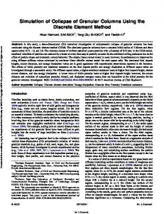
Fig. 2. Simulation results of exchange-bias shift as a function of the locally enhanced coupling constants, which accounts for spin reversal ability at a given point - visible oscillations in values result from numerical instabilities (a). The number of unreversed spins during a whole hysteresis loop creation – number of spins divided by a lattice square surface – as a function of the enhanced coupling constant JE (b). The results for different dilution level within period changed with the 0.01 step. The simulation was carried out for a 50x50 lattice, the standard deviation of atomic roughness σ=2, and the external magnetic field intensity ranged from -3 to 3.
Molecular and Quantum Acoustics vol. 25, (2004)
a)
39
Exchange bias shift (a. u.)
-1.2 -1.0
J_E=8..15
-0.8 J_E=7
-0.6 J_E=6
-0.4 J_E=5
-0.2 J_E=1..4
0.0 0
0.02
0.04
0.06
0.08
0.1
Global dilution p
b)
0.450 J_E=9..15
Unreversed spins (a. u.)
0.400
J_E=8
0.350 0.300
J_E=7
0.250 J_E=6
0.200 0.150
J_E=5
0.100 0.050
J_E=1..4
0.000 0
0.02
0.04
0.06
0.08
0.1
Global dilution p
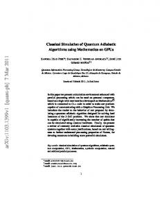
Fig. 3. Exchange bias shift (a) and a number of not reversed spins during one hysteresis loop cycle (b) as a function of dilution, which accounts for global distribution at random places, where exist locally enhanced coupling constants JE. The results for the JE values were taken from the range. The simulation was carried out for a 50x50 lattice, the standard deviation of atomic roughness σ=2, and the external magnetic field intensity ranged from -3 to 3
40
Błachowicz T.
JE
Fig. 4. Examples of hysteresis loops simulated at the constant global dilution level p=0.06, for a 50x50 lattice, standard deviation of atomic roughness σ=2, and the external magnetic field intensity changed within the range. This describes a use of different local coupling constants at the same constant global level of dilution (p).
p=0.3
p
Fig. 5. Examples of hysteresis loops simulated for the same enhanced coupling constant, JE=8, but for different levels of a global dilution p. Calculations were carried out for the 50x50 lattice, standard deviation of atomic roughness σ=2, and the external magnetic field intensity changed within the range. The dilution p falls into the range and was changed with the 0.01 step. However, the most top loop was calculated for the p=0.3 value.
Molecular and Quantum Acoustics vol. 25, (2004)
41
0.375 0.300 0.225 0.150 0.075
Cou plin g
5 con
7
9
11 sta 13 nt J 15 _E
p
3
0.1 0.07 0.04 0.01 io n
1
ilu t
0.000
D
Unreversed spins
0.450
Fig. 6. 3-D picture of number of unreversed spins during one single hysteresis loop cycle as a function of the global dilution p and locally increased coupling constant JE. In this way, the current results differ intrinsically from those provided by X. Illa, where under similar assumptions, where a single FM layer was coupled to quenched AFM region, the loops were closed and all FM spins seem to be reversible. 4. DISCUSSION OF RESULTS These results suggest, first of all, that a single FM at the FM/AFM interface was simulated. Locally enhanced exchange constants and the dilution level seem to represent the AFM influence on FM interfacial spins, rather than describe other types of physical effects like, for example, a superexchange interaction. The present results seem to correlate with the Domain State Model. In models of exchange-bias, as in the Domain State Model, there exists a distinction between interfacial domains and those located in the bulk region of the AFM.
42
Błachowicz T. It was proved there that the interface magnetization carries a part of the irreversible
anisotropy leading to exchange bias and the reversible part leading to enhanced coercivity [19-20]. These effects posses real counterparts not only in single crystal layers but even in polycrystalline structures in which some grains are stable, giving rise to exchange bias, and other parts are sensitive to any field direction [21-22]. In this investigation, places where the enhanced coupling constant is significantly larger than J=1 are not reversible. In other words, at random places a reversibility of spins is restricted or even forbidden. In this way JE parameter is the responsible for reversal ability at a given local point. The modified exchange constant can not be increased infinitely – hysteresis loops saturate for a given value of JE. In the case of the simulations here however, in the range between JE=5 and JE=8, loops are influences effectively (Fig. 4). The dilution calculated at random places counts for number of places to be possibly reversed, while, the local parameter which controls reversibility has its equivalence in experimental reality as crystal lattice dilutions or atom substitutions, which can be controlled during technological processes. This suggests that it’s possible to make an AFM structure magnetically more or less stable. In general, dilution efficiency depends on both local (JE) and global (p) factors. This fact is depicted in 3-dimensions in Fig. 6. There exists excellent experimental confirmation of exchange-bias, in Co/CoO systems, where CoO (AFM) structure was modified by inserting non-magnetic substitutions of the Co1-xMgxO type [23]. It seems that the simple approach provided here can be easily extended to cases where more FM layers are taken into account. This should prove that FM layers located far from the FM/AFM interface are governed by the J=1 coupling constant only, while a whole structure is revealed by an exchange-bias shift with a closed hysteresis loop. ACKNOWLEDGEMENTS This work was supported by the Polish State Committee for Scientific Research under Grant No 3 T11F 015 26. REFERENCES 1. B. Dieny, V. S. Speriosu, S. Metin, S. S. Parkin, B. A. Gurney, P. Baumgart, and D. R. Wilhoit, “Magnetotransport properties of magnetically soft spin-valve structures”, J. Appl. Phys. 69, 4774-4779, (1991)
Molecular and Quantum Acoustics vol. 25, (2004)
43
2. B. Dieny, “Giant magnetoresistance in spin-valve multilayers”, J. Magn. Magn. Mater. 136, 335-359, (1994) 3. A. Fert, T. Valet, and J. Barnas, “Perpendicular magnetoresistance in magnetic multilayers: Theoretical model and discussion”, J. Appl. Phys. 75, 6693-6698, (1994) 4. D. J. Monsma, J. C. Lodder, Th. J. A. Popma, and B. Dieny, “Perpendicular Hot Electron Spin-Valve Effect in a New Magnetic Field Sensor: The Spin-Valve Transistor”, Phys. Rev. Lett. 74, 5260-5263, (1995) 5. H. Kanai, K. Yamada, K. Aoshima, Y. Ohtsuka, J. Kane, M. Kanamine, J. Toda, and Y. Mizoshita, : “Spin-valve read heads with NiFe/Co90Fe10 layers for 5 Gbit/in2 density recording”, IEEE Trans. Magn. 32, 3368-3373, (1996) 6. H. Kanai, J. Kane, K. Yamada, K. Aoshima, M. Kanamine, J. Toda, and Y. Mizoshita, “NiFe/CoFeB spin-valve heads for over 5 Gbit/in2 density recording”, IEEE Trans. Magn. 33, 2872-2874, (1997) 7. H. Kanai, M. Kanamine, A. Hashimoto, K. Aoshima, K. Noma, M. Yamagishi, H. Ueno, Y. Uehara, and Y. Uematsu, “PdPtMn/CoFeB synthetic ferrimagnet spin-valve heads”, IEEE Trans. Magn. 35, 2580-2582, (1999) 8. S. Kaka, J. P. Nibarger, and S. E. Russek, N. A. Stutzke, and S. L. Burkett, “Highfrequency measurements of spin-valve films and devices”, J. Appl. Phys. 93, 7539-7544, (2003). 9. B. Beschoten, A. Tillmanns, J. Keller, G. Güntherodt, U. Nowak, and K. D. Usadel, “Domain State Model for Exchange Bias: Influence of Structural Defects on Exchange Bias in Co/CoO”, Adv. Solid State Phys. 42, 419-431, (2002) 10. J. Keller, P. Miltényi, B. Beschoten, G. Güntherodt, U. Nowak, and K. D. Usadel, “Domain state model for exchange bias. II. Experiments”, Phys. Rev. B 66, 14431-14442, (2002) 11. U. Nowak, K. D. Usadel, “Diluted antiferromagnets in a magnetic field: A fractal-domain state with spin-glass behavior”, Phys. Rev. B 44, 7426-7432, (1991) 12. U. Nowak, K. D. Usadel , J. Keller, P. Miltényi, B. Beschoten, and G. Güntherodt, “Domain state model for exchange bias. I. Theory”, Phys. Rev. B 66, 14430-14439, (2002) 13. T. Mewes, R. Lopusnik, J. Fassbender, B. Hillebrands, M. Jung, D. Engel, A. Ehresmann, and H. Schmoranzer, „Suppression of exchange bias by ion irradiation”, Appl. Phys. Lett. 76, 1057-1059, (2000) 14. K. Binder, The Monte Carlo Method in Condensed Matter Physics, Springer-Verlag, Berlin Heidelberg 1995
44
Błachowicz T.
15. J. P. Sethna, K. Dahmen, S. Kartha, J. A. Krumhansl, B. W. Roberts, and J. D. Shore, “Hysteresis and hierarchies: Dynamics of disorder-driven first-order phase transformations”, Phys. Rev. Lett. 70, 3347-3350, (1993) 16. R. Blossey, T. Kinoshita, and J. Dupont-Roc, “Random-field Ising model for the hysteresis of the prewetting transition on a disordered substrate”, Physica A 248, 247-272, (1998) 17. U. Nowak, K. D. Usadel, and J. Esser, : “Modified scaling relation for the random-field Ising model”, Physica A 250, 1-7, (1998) 18. X. Illa, E. Vives, and A. Planes, “Metastable random-field Ising model with exchange enhancement: A simple model for exchange bias”, Phys. Rev. B 66, 224422-224429, (2002) 19. U. Nowak, A. Misra, and K. D. Usadel, “Domain state model for exchange bias”, J. Appl. Phys. 89, 7269-7271, (2001) 20. U. Nowak, A. Misra, and K. D. Usadel, “Modeling exchange bias microscopically”, J. Mag. Mag. Mat. 240, 243-247, (2002) 21. R. D. McMichael, M. D. Stiles, P.J. Chen, and W. F. Egelhoff, Jr, “Ferromagnetic resonance studies of NiO-coupled thin films of Ni80Fe20”, Phys. Rev. B 58, 8605-8612, (1998) 22. M. D. Stiles and R. D. McMichael, “Model for exchange bias in polycrystalline ferromagnet-antiferromagnet bilayers”, Phys. Rev. B 59, 3722-3733, (1999) 23. P. Miltényi, M. Gierlings, J. Keller, B. Beschoten, G. Güntherodt, U. Nowak, and K. D. Usadel, “Diluted Antiferromagnets in Exchange Bias: Proof of the Domain State Model”, Phys. Rev. Lett. 84, 4224-4227 (2000)