We present a system for constructing 3D models from simple hand-drawn sketches. .... 3.3 Recognition rate vs. training size for least square method. . . . . . . 20 ... 4.1 Shapes of basic symbols: arc, ellipse, triangle, square, open rectangle. 24 .... 2. 2D sketch applications. These applications smooth sketch strokes and classify.
Sketch-based Instancing of Parameterized 3D Models by Dan Xiao M.Sc., Zhejiang University, 2002
A THESIS SUBMITTED IN PARTIAL FULFILLMENT OF THE REQUIREMENTS FOR THE DEGREE OF
Masters of Science in THE FACULTY OF GRADUATE STUDIES (Department of Computer Science)
We accept this thesis as conforming to the required standard
The University of British Columbia September 2004 c Dan Xiao, 2004
Abstract We present a system for constructing 3D models from simple hand-drawn sketches. The system exploits a priori knowledge about the type of object being sketched. In particular, we assume that the class of object being drawn is known, (e.g., a rocket ship) and that the object will be drawn using a fixed number of known components. By using these assumptions, we show that we can build a sketch-based modeling system that, while object specific, is capable of quickly creating geometric models that are beyond the scope of current sketch-based modeling approaches. Key to our approach is the use of a K-means classifier for labeling each drawn stroke as being a particular component in the generic model. We demonstrate our approach by applying this classifier to face and rocket sketches.
ii
Contents Abstract
ii
Contents
iii
List of Tables
v
List of Figures
vi
Acknowledgements
viii
1 Introduction
1
1.1
Motivation
. . . . . . . . . . . . . . . . . . . . . . . . . . . . . . . .
1
1.2
System Overview . . . . . . . . . . . . . . . . . . . . . . . . . . . . .
3
1.3
Application of Sketch Recognition . . . . . . . . . . . . . . . . . . .
3
1.4
Thesis Outline . . . . . . . . . . . . . . . . . . . . . . . . . . . . . .
4
2 Related Work
5
2.1
Attributes of a Sketch Recognition System . . . . . . . . . . . . . . .
5
2.2
Algorithms for Object Recognition . . . . . . . . . . . . . . . . . . .
6
2.3
2D Sketch Recognition . . . . . . . . . . . . . . . . . . . . . . . . . .
7
2.4
3D Sketch-based Modeling . . . . . . . . . . . . . . . . . . . . . . . .
9
2.5
Summary . . . . . . . . . . . . . . . . . . . . . . . . . . . . . . . . .
11
iii
3 Single-stroke Classification
12
3.1
Problem . . . . . . . . . . . . . . . . . . . . . . . . . . . . . . . . . .
12
3.2
The Features . . . . . . . . . . . . . . . . . . . . . . . . . . . . . . .
13
3.3
Methods for Stroke Classification . . . . . . . . . . . . . . . . . . . .
15
3.3.1
Least Squares Method . . . . . . . . . . . . . . . . . . . . . .
15
3.3.2
K-means Method . . . . . . . . . . . . . . . . . . . . . . . . .
16
3.3.3
Expectation-Maximisation Method . . . . . . . . . . . . . . .
18
3.4
Classifier Comparison . . . . . . . . . . . . . . . . . . . . . . . . . .
19
3.5
Summary . . . . . . . . . . . . . . . . . . . . . . . . . . . . . . . . .
22
4 Sketch Recognition and 3D Model Construction 4.1
4.2
23
Sketch Recognition: Training . . . . . . . . . . . . . . . . . . . . . .
23
4.1.1
Shapes . . . . . . . . . . . . . . . . . . . . . . . . . . . . . . .
23
4.1.2
Choice of Features . . . . . . . . . . . . . . . . . . . . . . . .
24
4.1.3
Sketch Recognition: Matching . . . . . . . . . . . . . . . . . .
28
3D Model Construction . . . . . . . . . . . . . . . . . . . . . . . . .
28
5 Results
30
5.1
Face Sketching . . . . . . . . . . . . . . . . . . . . . . . . . . . . . .
30
5.2
Rocket Sketching . . . . . . . . . . . . . . . . . . . . . . . . . . . . .
31
5.3
Discussion . . . . . . . . . . . . . . . . . . . . . . . . . . . . . . . . .
31
6 Conclusions and Future Work
35
Bibliography
36
Appendix A User Interface
39
iv
List of Tables 1.1
Correspondences between strokes and components of a rocket. . . . .
2
4.1
Description of components for face. . . . . . . . . . . . . . . . . . . .
26
4.2
Description of components for rocket.
26
5.1
Comparisons of drawing and recognized face components with incorrect recognition.
. . . . . . . . . . . . . . . . .
. . . . . . . . . . . . . . . . . . . . . . . . . . . . .
v
31
List of Figures 1.1
An example of sketch recognition and modeling.
. . . . . . . . . . .
2
1.2
System Overview. . . . . . . . . . . . . . . . . . . . . . . . . . . . . .
2
2.1
Design process [13]. . . . . . . . . . . . . . . . . . . . . . . . . . . . .
6
2.2
Example of user interface: Teddy. . . . . . . . . . . . . . . . . . . . .
10
2.3
Another example of user interface: Chateau. . . . . . . . . . . . . . .
10
3.1
Features extracted from a gesture for identification. . . . . . . . . . .
14
3.2
Examples from the gesture set used for evaluation. . . . . . . . . . .
20
3.3
Recognition rate vs. training size for least square method. . . . . . .
20
3.4
Recognition rate vs. training size for K-means method. . . . . . . . .
21
3.5
Recognition rate vs. training size for EM method. . . . . . . . . . .
21
4.1
Shapes of basic symbols: arc, ellipse, triangle, square, open rectangle.
24
4.2
Features of head used for classification. . . . . . . . . . . . . . . . . .
26
4.3
Illustration of face components. . . . . . . . . . . . . . . . . . . . . .
27
4.4
Illustration of rocket components. . . . . . . . . . . . . . . . . . . . .
27
4.5
Modeling parameters for tapered cylinder and ellipsoid. . . . . . . .
29
5.1
Face modeling with correct recognition. . . . . . . . . . . . . . . . .
32
5.2
Rocket modeling with correct recognition. . . . . . . . . . . . . . . .
33
5.3
Face modeling with incorrect recognition. . . . . . . . . . . . . . . .
34
vi
A.1 The interface of modeling system. . . . . . . . . . . . . . . . . . . . .
vii
40
Acknowledgements I would like to give my great gratitude to my supervisor, Dr. Michiel van de Panne, for his invaluble advice on my thesis work. Without him, this would never have been completed. I am also very grateful to Dr. Nando de Freitas, who is giving the interesting machine learning course and stimulate the idea in this thesis. To Jason Harrison, who contribute useful books and papers. Also to Peng Zhao, Yizhen Cai and Xiaojing Wu for providing several discussions.
Dan Xiao
The University of British Columbia September 2004
viii
Chapter 1
Introduction 1.1
Motivation
“A picture speaks a thousand words”. People often rely on sketches when they try to convey ideas to others. We all have the experience of drawing something. Of all drawers, children are among the most fanatic. They like to convert what they see and think into pictures. Sometimes their pictures are simply drawn but they are at the same time capable of conveying much information. Creating and animating 3D models is currently not possible, however, without significant training and expertise. New technologies are thriving in our modern society. One common characteristic of successful technologies is their ease of use, so that people can grasp those technologies in a short period of time and use them in an easy way. With devices such as PDAs and Tablet PCs, there exists hardware that largely replicates the feel and function of a pencil or pen or paper. What now remains is for new software applications to exploit these new capabilities. Our system can interpret a limited class of 2D sketeches as 3D objects, and thus represents such a new application.
1
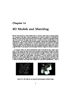
Figure 1.1: An example of sketch recognition and modeling.
Figure 1.2: System Overview.
Stroke 1 2 3 4 5
Resulting component cone body tail left wing right wing
Table 1.1: Correspondences between strokes and components of a rocket.
2
1.2
System Overview
Figure 1.1 shows an example drawn and recognized by our system. Each pen stroke in the graph is recognized as a component of the object and then constructs a component of the 3D model. In the above graph, a rocket is drawn with 5 pen strokes and later, a 3D rocket model is displayed with 5 components. Each pen stroke represents one component and their correspondences are illustrated in Table 1.1. The overall system structure is given in Figure 1.2.
1.3
Application of Sketch Recognition
The application domains of Freehand Sketch Recognition System (FSRS) include: • 3D modeling based on sketching interface, such as computer aided design (CAD). • Query by sketch : image database retrieval. A long-standing dream in computer-aided design is the possibility of using freehand sketching as the language for interactive design. The ability to sketch a 3D object, predict its performance, and re-design it interactively based on physics-based feedback would bring the power of state-of-the-art CAD tools into the critical, early design phase. The enormous potential of sketch-based interfaces is widely recognized, and has been broadly pursued. However, the practical use of such attempts has remained limited because these interfaces have been primarily 2D, losing much of the benefit of mainstream 3D CAD. In order to become truly 3D, a sketch interface must automatically be able to reconstruct the spatial geometry from a single 2D sketch in near real-time, much like a human observer does implicitly.
3
1.4
Thesis Outline
The rest of this thesis is organized as follows. In Chapter 2, we discuss work related to this project. Chapter 3 explores how to label individual strokes using classification and compares different classifiers. Chapter 4 describes our implemented system. Chapter 5 presents results. We make conclusions and discuss future work in Chapter 6.
4
Chapter 2
Related Work 2.1
Attributes of a Sketch Recognition System
Freehand sketching can play an important role in the realm of user-interfaces for graphics systems. Sketching appears to be a natural communication language, enabling fast conveyance of qualitative information while not burdening the creativity of the user or disrupting the flow of ideas. As illustrated in Figure 2.1, sketching is a key element in modeling, developing and defining a design result. During the whole design process, sketching often provides the input for conceptual design. [17] suggests that a sketch recognition technology must meet three main requirements: it must deal reliably with the pervasive variability of hand sketches, provide interactive performance, and be easily extensible to new configurations. User interfaces based on sketching can generally be divided into three categories, according to the level of information they intend to gather from the input sketch [22]: 1. Drawing Pads. Basic sketching is allowed for general purpose drawings. Input strokes are smoothed and many other graphic tools are provided. 2. 2D sketch applications. These applications smooth sketch strokes and classify them into 2D primitives, such as lines, arcs, and splines. Some geometric 5
Figure 2.1: Design process [13]. constraints and relationships among the entities are utilized to further refine the sketch. 3. 3D sketchers. Sketches are analyzed as representing rough projections of 3D scenes. Sketch strokes are identified as basic geometrical shapes, such as lines, arcs and corners. However, some of the sketch strokes do not necessarily represent what they appear to be since the analyzed sketch represents a rough projection of a three dimensional scene [11, 14].
2.2
Algorithms for Object Recognition
The sketch recognition problem is strongly related to the object recognition problem in computer vision. A broad class of such object recognition problems have benefited from statistical learning machinery. The use of Principle Component Analysis (PCA) has produced good results [25] in the area of face recognition. On more general object recognition tasks, several other learning methods such as Bayes classifier [21] and decision tree learning [28] have been applied. The technique of boosting is proven to be a viable method of feature selection in [26]. Support vector machine methods have demonstrated success in template matching problems such as
6
recognizing pedestrians in [16]. [2] and [31] present a novel approach to measure similarity between 2D shapes and exploit it for object recognition. In order to solve the correspondences problem, they attach a descriptor, the shape context, to each point. The shape context at a reference point captures the distribution of the remaining points relative to it, thus offering a globally discriminative characterization. In this way, they treat recognition in a nearest-neighbor classification framework as the problem of finding the stored prototype shape that is maximally similar to that in the image.
2.3
2D Sketch Recognition
Research on sketch recognition and interpretation has a long history. A variety of systems have incorporated gesture recognition into their user interface. The development of a Freehand Sketch Recognition System involves three stages: 1. Stroke-level recognition which interprets the pixels and produces low-level geometric primitives such as lines and curves. 2. 3D modeling based on 2D sketches. 3. Multi-stroke understanding. Each sketch of an object consists of multiple strokes. The first step in intepreting a sketch is to classify individual pen strokes by processing them. Usually there are two assumptions in this area, one is that each pen stroke symbolizes a single shape, such as a single curve segment or triangle segment, whichever fits the stroke best. Much of the previous work has relied either on using stroke methods in which an entire symbol must be drawn as single stroke [20, 10, 4], or single primitive methods in which each stroke must be a single line, arc, or curve [18, 6, 27]. Another one used in [3] is that multiple primitives can be drawn in the same pen stroke. In this way, a square can be drawn as four individual pen strokes or a single pen stroke 7
with three 90◦ bends. The key challenge is determing which bumps and bends are drawn intentionally and which are unintentionally. Arvo and Novins described a kind of stroke-level recognition algorithm [1]. Different from traditional ways of recognizing sketches, their method continuously morphs raw input strokes into ideal geometric shapes. Another stroke-level recognition algorithm is a domain-independent system for sketch recognition [29]. Users are allowed to draw sketches as naturally as how they do on paper. The system then recognizes the drawing through imprecise stroke approximation which is implemented in a unified and incremental procedure. This method can handle smooth curves and hybrid shapes as gracefully as it does to polylines. With a feature-area verification mechanism and the intelligent adjustment in a post-process, the system can produce the results intended by the user. Rubine presented a trainable gesture recognizer which used a “linear machine” classifier to discriminate gestures [20]. Each gesture class is associated with a linear evaluation function using 13 features. In order for training, appropriate weights are learned for each attribute in the linear function. The attributes consider aggregate properties of a pen stroke, and it is possible that two different gestures would have the same aggregate properties. Recent studies show us some interesting gesture-based interfaces in which the user specifies commands by simple drawings. GRANDMA, a tool for building gesture-based applications introduced in [19], supports the integration of gestures and direct manipulation. It allows views that respond to gestures and views that respond to clicks and drags to coexist in the same interface. Our work is closely related to this in that we also a set of stroke features and then apply a classifier to discriminate different gestures. Landay and Myers advanced an interactive sketching tool called SILK in which designers can quickly sketch out a user interface and transform it into a fully operational system [12]. As the designer sketches, the recognizer of SILK matches
8
the pen strokes to symbols representing various user interface components, and returns the most likely interpretation. Their recognizer is limited to single-stroke shapes drawn in certain preferred orientations. [23, 24] have developed a program called SketchIT that can transform a sketch of a mechanical device into working designs. Electronic Cocktail Napkin [5] employs a trainable recognizer that works for multi-stroke shapes. The recognition process consists of glyph (low-level) and configuration (high-level) recognition. A glyph is described by a state transition model of the pen path, the aspect ratio and size of the bounding box, and the number of corner points. Configuration recognition takes the spatial relationships between the glyphs into consideration. This method is sensitive to changes in orientation, and the 3x3 grid may be inadequate for symbols containing small features.
2.4
3D Sketch-based Modeling
Zeleznik et al. have extended the use of gesture recognition for 3D modeling[30]. The SKETCH system they proposed attempts to combine 2D image with 3D computer modeling systems to create an environment for rapidly conceptualizing and editing approximate 3D scenes. All interaction with SKETCH is via a three-button mouse, occasional use of one modifier key on the keyboard, and a single orthographic window onto the 3D scene. The Teddy system [8] in Figure 2.2 is aimed especially at the modeling of simple free form objects. The system is able to inflate 2D closed curves into 3D objects, which can then be edited using simple gestures. The interface shown in Figure 2.3 is Chateau [7], a prototype system in which the user gives the hints to the system by highlighting related lines and the system suggests possible operations based on the hints, shown in the thumbnails at bottom.
9
Figure 2.2: Example of user interface: Teddy.
Figure 2.3: Another example of user interface: Chateau.
10
2.5
Summary
In this chapter, we presented a review of sketch recognition systems, 2D sketch recognition methods, along with some 3D sketch-based modeling examples. In the next chapter, we will present some machine learning methods used for gesture recognition.
11
Chapter 3
Single-stroke Classification One of the goals of our work is to obtain an efficent classifer as well as a rich and meaningful feature vectors. In this chapter, we compare several machine learning methods that classify strokes into one of several categories based upon the stroke feature vectors [20]. The selection of useful features and a good classifier will determine the effectiveness of our gesture recognizer.
3.1
Problem
Each gesture is defined as an array g of coordinate values and time. gp = (xp , yp , tp )
0≤p