In Proc. of the 1994 Complex Systems Engineering Synthesis and Assessment Technology Workshop (CSESAW ‘94), Silver Spring, MD, pp 217-224, July 1994.
Software Assembly for Real-Time Applications Based on a Distributed Shared Memory Model* David B. Stewart, Matthew W. Gertz, and Pradeep K. Khosla Department of Electrical and Computer Engineering and The Robotics Institute, Carnegie Mellon University, Pittsburgh, PA 15213
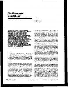
Development time and cost of real-time applications can be significantly reduced by reusing software from previous applications. With today’s systems, however, even if some software is reused, a large amount of new code is still required to create the “glue” which integrates modules created by programmers at different sites. A new software engineering paradigm, called “software assembly,” is the process of developing an application simply by combining software modules from distributed libraries, without the need to write nor automatically generate any glue code. In this paper, the underlying framework to support software assembly of real-time applications is presented. The primary contribution is the notion of port-based objects, which combine object-based design with the port-automaton theory, in order to model and develop reconfigurable software modules. The integration of these modules in a distributed shared memory environment is possible through the use of a global state variable communication mechanism. Support for the framework has been implemented as part of the Chimera Real-Time Operating System. We have also designed a hypermedia user interface called Onika which allows real-time applications to be assembled graphically. 1
Introduction
Transfer and reuse of real-time application software is difficult and often seemingly impossible due to the incompatibility between hardware and systems software at different sites. This has meant that new technology developed at one site must be reinvented at other sites, if in fact it can be incorporated at all. Technology transfer, therefore, has been a very expensive endeavor, and the reuse of software from previous applications has been virtually non-existent. An an example, consider users who are developing a real-time application and may need new software algorithms developed at other sites. Currently, users may go to the library or search through the network for keywords, then find a book or journal article describing the mathematical theory or computer science algorithm, and perhaps also a description of the original implementation. After they have printed a copy of the paper, they read the article closely, then spend significant time writing, testing, and debugging code to implement the algorithm on their own system. Once that is done, they write more code to integrate the new algorithm into their application, and perform further testing and debugging. This process can easily take days or weeks of the person’s time for each algorithm needed for their application, and thus take many months to complete the programming of an entire application. The ultimate application programming environment, however, would allow for complete software reuse and the ability to quickly transfer technology from remote sites. There would exist a global distributed software library based on the information super-highway, similar to the hypermedia information system currently available on the World-Wide Web. Users who need the algorithm would search the library to find the appropriate book or article as is done today. However, when they find a suitable article, they not only get the theory from the article, but they can also follow a hyperlink to a reusable software module created by the authors, with the algorithm already programmed, fully tested, and debugged. With an action as simple as a mouse-click, that software algorithm is copied into the user’s personal library, and is ready to be used in their application. This process would take a few minutes at most. The user could then assemble their software application by putting together these software building-blocks through the use of a graphical user interface. Within hours, a complete application could be assembled, as compared to the months that it would take to do so using conventional methods. We propose the use of a software assembly paradigm to obtain the programming environment described above. Software assembly is the process of synthesizing an application without writing or automatically generating any new glue The research presented in this paper is supported, in part, by Sandia National Laboratories, NASA, the Dept. of Electrical and Computer Engineering and the Robotics Institute at Carnegie Mellon University. Partial funding for David B. Stewart is provided by the Natural Sciences and Engineering Research Council of Canada (NSERC) through a graduate fellowship. Partial funding for Matthew W. Gertz is provided by NASA Langley Research Center through a GSRP fellowship.
code. Software assembly is achieved by designing the underlying software as dynamically reconfigurable modules. A real-time operating system (RTOS) provides the services required to automatically integrate these modules in a shared memory distributed environment. In Section 2, we first present related work in the area of software reuse. In Section 3 we introduce the notion of portbased objects, which combines object-based design with the port-automaton model, and which forms the basis of developing reconfigurable real-time software that can be assembled. In Section 4 we present the global state variable table mechanism, which we have designed to allow for the automatic integration of port-based objects in a distributed shared memory environment. Access to the global software database and assembly of the reconfigurable software modules is performed through a graphical user interface, as described in Section 5. Finally, in Section 6, we summarize our work on software assembly for quickly developing distributed shared memory real-time applications. 2
Related Work
There has been significant research in the area of software reuse, with three major directions emerging: software synthesis, interface adaptation, and object-based design. Software synthesis, also known as automatic code generation, generally employs artificial intelligence techniques such as knowledge bases [1] [3] [18] and expert systems [11] [16] to generate the “glue” code for automatically integrating reusable modules. As input, they receive information about the software modules, the interface specifications and the target application, and as output produce code using both formal computation and heuristics. For a truly generic framework, however, it is desirable that the integration of software be based on the interfaces alone, and not on the semantics of the modules or application, as the latter results in the need for large knowledge bases. Furthermore, software synthesis only allows for statically configuring an application, and usually does not support dynamic reconfiguration. Interface adaptation involves modifying the interfaces of software modules based on the other software modules with which they must communicate in order to obtain the required software integration. In these systems, an interface specification language is used to provide a general wrapper interface and to allow meaningful data to be interchanged between the modules [10] [12] [14]. This method has led to the notion of a software bus, where an underlying server or transport mechanism adapts to the software module, rather than having the software modules adapt to the transport mechanism [4] [15]. None of these methods have been adapted to real-time systems, and there are no clear extensions which would ensure that interface adaptation and communication between modules can be performed in real-time. Object-based design addresses the root of the problem of software reuse by defining specifications for software module interfaces from the outset. An object is a software entity which encapsulates data and provides methods as the only access to that data [6]. Wegner distinguishes between two types of object design methodologies: object-based design (OBD) and object-oriented design (OOD) [25]. Whereas OBD only defines the encapsulation of data and access to that data, OOD is an extension which also defines the interrelation and interaction between objects. The interrelation of objects in OOD is defined through inheritance using the notions of classes, superclasses, and metaclasses [25]. An object-oriented programming language generally performs runtime dynamic binding to support this inheritance, and objects of different classes communicate with each other through messages, where the message invokes the method of another object. Such dynamic binding and message passing creates unpredictable execution delays, especially in a distributed environment, and as a result is not suitable for the design of real-time systems [5]. The Chaos Real-Time Operating System [17] was designed to use object-oriented design with real-time systems. Chaos addresses the the dynamic binding issue by performing static binding during the compilation and linking stages, thus allowing for predictable execution of the real-time application. Although object-oriented design is suitable for dynamically reconfigurable systems, the use of static binding for a real-time application eliminates that capability, and results in a system that is only statically configurable. The Chaos system addresses the real-time message passing issue by creating a variety of specialized messages which are tailored to the target application. As stated in [5] this, to some extent, ruins the object model’s uniformity, and thus partially defeats the purpose of using the object-oriented methodology for developing real-time systems. We have taken an alternate approach which avoids the real-time problems associated with object-oriented design, while maintaining the advantages of using objects for software reusability and reconfigurability. As described in the next section, we combine the advantages of object-based design with the port-automaton computational model to obtain the required real-time predictability.
3
Port-Based Objects
We combine the use of objects with the port-automaton formal computation model [24] for interaction between the objects, instead of classifying objects by their inheritance or by their interrelation through messages. A port-automaton is a model of a concurrent process, where an output response is computed as a function of an input response. The automaton executes asynchronously and independently, and whenever input is needed, the most recent data available is obtained. The automaton may have internal states; however all communication with other concurrent processes are through the ports. The port-automaton theory was first applied to robotics by Lyons and Arbib [13], who constructed a special model of computation based on it, which was called Robot Schemas. The schema used the port-automaton theory to formalize the key computational characteristics of robot programming into a single mathematical model. Arbib and Ehrig extended the work on robot schemas for algebraically specifying modular software for distributed systems by using port specifications to link modules [2]. The specification presented requires that there be exactly one input for every output link, and vice versa. The specification does not include any notions of objects in order to obtain reusability of the modules and reconfigurability of a task set, and there is no implementation presented that can map their specification into an actual system. In our research, these port specifications have been combined with object-based design in order to create the port-based object model of a reconfigurable software module [19]. A port-based object is defined as an object, with various ports for real-time communication. As with any standard object [6], each module has a state and is characterized by its methods. The internals of the object are hidden from other objects. Only the ports of an object are visible to other objects. A simplified model of a port-based object is shown in Figure 1. Each module has zero or more input ports, zero or more output ports, and may have any number of resource ports. Input and output ports are used for communication between tasks in the same subsystem, while resource ports are used for communication external to the subsystem, such as with the physical environment, other subsystems, or a user interface. A link between two objects is created by connecting an output port of one module to a corresponding input port of another module. We extend the port specifications as compared to that presented with the port-automaton theory so that an input port can be spanned into multiple outputs and outputs can be joined into a single input. In addition, operating system services are provided such that the communication through these ports can be performed in real-time and port-based objects can be reconfigured dynamically (see Section 4). A single output may be used as input by multiple tasks. In our diagrams, we represent such fanning of the output with just a dot at the intersection between two links, as shown in Figure 2. In that example, both modules A and B require the same input p, and therefore the module C fans the single output p into two identical outputs, one for each A and B. If two modules have the same output ports, then a join connector is required to ensure the integrity of the potentially conflicting data, as shown in Figure 3. A join connector is a special object which takes two or more conflicting inputs, and produces a single non-conflicting output based on some kind of combining operation, such as a weighted average. In this example modules A and B are both generating a common output p. In order for any other module to use p as an input, it must only connect to a single output p. The user can modify the output ports of modules with conflicting outinput ports x1 xn
:
port-based object
y1 output ports ym
:
A p
C
B
resource ports, for communication with sensors, actuators, and other subsystems Figure 1: Simplified model of a port-based object
A
B
Figure 2: Fanning an output into multiple inputs
q p
A
p r
B
q p’ p’’
join connector
r
Figure 3: Joining multiple outputs into a single input
p
puts using the aliasing features provided by the RTOS and graphical user interface, such that they are two separate, intermediate variables. In our example, the output of module A becomes p’, and the output of module B becomes p”. The join connector takes p’ and p” as inputs, and produces a single unambiguous output p. A task is not required to have both input and output ports. Sensory-input modules, for example, only have output ports as their input is received from the environment through the resource ports. Similarly actuators generally only have input ports, and their output is transferred to the physical world through the resource ports. Other tasks may generate data internally or receive data from an external subsystem (e.g. trajectory generator and vision subsystem interface) , or just gather data (e.g. data logger and graphical display interface) and hence not have input or output ports. 3.1
Configuration Verification
A task set is formed by selecting multiple objects which together form either an open-loop or closed-loop system. Each object executes as a separate task on one of the RTPUs in the real-time environment. An example of a fairly simple task set is the PID joint control of a robot, as shown in Figure 4. It uses three modules: the joint position trajectory generator, the PID joint position controller, and the torque-mode robot interface. A legal configuration exists when there is exactly one output port for every input port in the task set, and that there are no two modules which produce the same output. The correctness of a configuration can be verified analytically using set equations, where the elements of the sets are the state variables. A configuration is legal only if ( Y i ∩ Y j ) = ∅ , for all i,j such that 1 ≤ i,j ≤ k ∧ i≠j (1) and
k
k
j=1
j=1
∪ Xj ⊆ ∪ Yj
(2)
where Xj is a set representing the input variables of module j, Yj is a set representing the output variables of module j, and k is the number of modules in the configuration. 3.2
Internal Structure
A port-based object contains several special methods which are called by the operating system in response to various signals. The methods allow for separate creation and activation of the software modules, periodic cycling or aperiodic handling of events, and error handling and recovery. Details of the internal structure of a port-based object, as well as C-language interface specifications and templates for developing software using the port-based object model, are given in [19]. Reconfigurable software modules created using the specifications can then be used in any application that makes use of the software assembly paradigm described in this paper. 4
Control Module Integration
In order to support our abstraction of port-based objects, a real-time mechanism which allows for the multi-threaded communication of multiple tasks in a multiprocessor system is required. In addition, the communication mechanism must be flexible for adding and deleting communication channels as the task set may be dynamically changing. The overhead of the mechanism must also be low, so as to not dominate usage of the CPU. To address this problem, we have designed a state variable table mechanism (which we abbreviate as SVAR) for providing the real-time intertask communication of a task set in a distributed shared memory environment [21]. The com-
θd trajectory generator joint position θd from user
θm
θm
PID joint position controller
torque-mode robot interface
τr
from robot: raw joint pos/vel data
Figure 4: Example of PID joint control.
θm
to robot: joint move command
θm
munication mechanism is based on the combined use of global shared memory and local memory for the exchange of data between modules, as shown in Figure 5. Every input port and output port is a state variable. A global state variable table is stored in the shared memory. The variables in this table are a union of the input port and output port variables of all the modules that can be configured into the system. Tasks corresponding to each control module cannot access this table directly. Instead, every task has its own local copy of the table, called the local state variable table. Only the variables used by the task are kept up-to-date in the local table. Since each task has its own copy of the local table, mutually exclusive access is not required. At the beginning of every cycle of a task, the variables which are input ports are transferred into the local table from the global table. At the end of the task’s cycle, variables which are output ports are copied from the local table into the global table. This design ensures that data is always transferred as a complete set, since the global table is locked whenever data is transferred between global and local tables. By using global state variables, tasks can be developed independent of the target application, as the only requirement is that the input constants and variables required by that task are produced by some other task. The underlying operating system mechanisms take care of all of the synchronization and setting up the communication paths to ensure that the data is at the correct place when it is required. Furthermore, tasks can be dynamically reconfigured, as a new task being swapped into the system immediately has access to the constants and variables which were used by the task being swapped out of the system. The global state variable table mechanism and other support for integrating port-based objects have been implemented in the Chimera RTOS [20] [23]; analysis of the mechanism and performance benchmarks are given in [19]. 5
Software Assembly through Graphical User Interfaces
Software assembly of reconfigurable software modules is performed by the user through a hypermedia user interface which we call Onika [7]. In this section, we give a brief overview of Onika. The reader who wishes more in-depth information should refer to [9]. Onika is a visual programming environment developed at Carnegie Mellon University. It allows the user to directly control and manipulate tasks as implemented in the Chimera RTOS. The port-based objects are stored in software libraries which may be either remote or local. When Onika is launched, it searches user preferences for hyperlink anchors to software libraries. Modules from remote libraries are downloaded and automatically linked with the local modules into a Chimera executable as needed. An iconic hyperlink is generated on-the-fly for each task, and is displayed to the user within a library window. The user can retrieve a variety of information about any given task by clicking on its icon, and can also modify the modules through this hyperlink (if allowable). The icon is displayed as a portbased object, showing its input and output ports clearly, as well as its current status, its name, and its frequency. Onika links with Chimera via a network, using two sockets. One socket is for bi-directional synchronous communication, and is used to issue commands and receive acknowledgments and data from Chimera. The other socket is unidirectional and used by Chimera to send signals to Onika, including error signals and special user-defined signals such as “job completed”. The user creates configurations (also called jobs in Onika) by placing icons from the library onto a job canvas. Onika sends a command to Chimera to spawn a new task for each icon placed onto the canvas. The tasks automatically inter-
Global State Variable Table
local state variable table
local state variable table
local state variable table
local state variable table
task module A1
task module Aj
task module K1
task module Kj
Processor A
Processor K
Figure 5: Structure of state variable table mechanism for control module integration
connect graphically with those which share common data ports already placed into the configuration, and represent a direct mapping to the global state variable table communication channels that exist in the real-time environment. The configurations are thus assembled graphically, and can be saved for later recall. The individual tasks can be turned on and off with simple mouse-clicks, and killed by selecting and deleting their icons. Certain task parameters can be changed easily, such as frequency, configuration constants, and aliases applied to I/O ports which do not match the local naming conventions. A status window gives more detailed information on the current status of real-time tasks and values of state variables. Assuming that configurations have been previously saved, reconfiguration into a new job from the current job can be achieved within Onika with a simple mouse-click. The user specifies the configuration which should be loaded from a file navigator. The saved configuration contains hyperlinks to the various modules it needs. Onika reads these in, and compares the links of the two configurations. It then constructs the sequence of events necessary to dynamically reconfigure from the current job to the next. These instructions are sent to Chimera in the form of command packets, and the real-time operating system reconfigures to the new job. Onika checks Chimera’s reply to determine if the configuration was successful, and updates the job canvas and the status information to reflect the current configuration. Figure 6 shows an example of an Onika job canvas. Each icon represents a port-based object. Shaded icons have been created and activated, while white icons are created but not activated. The programmer can create a pictorial iconic hyperlink to a configuration, which can then be stored in a higher-level library called a job dictionary. If the job requires some user input for execution (such as the desired endpoint in a joint motion job), this information can be pre-saved in a user I/O object, which is also assigned a pictorial icon and stored in the dictionary. Both jobs and objects can be viewed or edited by clicking on these pictorial anchors. Syntax and semantics are made apparent by the color and shape of each icon’s edges. Jobs and objects are arranged sequentially, fitting together like puzzle pieces, in order to form an application, as shown in Figure 7. When executed, Onika uses dynamic reconfiguration to traverse the application. A job which is finished (e.g. the trajectory endpoint has been reached) sends a signal to Onika, which then proceeds to the next job in the sequence. Onika and Chimera have been used several times to transfer technology and control multisensor systems during demonstrations of a virtual laboratory to top-level administrators and scientists at Sandia National Laboratories. Details of using software assembly for virtual laboratories can be found in [8]. 6
Summary
In this paper we introduce the notion of software assembly for real-time applications which are implemented in a distributed shared memory environment. The primary contribution is the notion of port-based objects, which combine object-based design with the port-automaton theory, in order to model and develop reconfigurable software modules. The real-time communication between port-based objects is performed through a global state variable mechanism that has been incorporated into the Chimera Real-Time Operating System. Software assembly and control of multi-sensor systems is performed by the user through a graphical user interface which we call Onika. Onika has been used to transfer technology in a virtual laboratory environment.
Figure 6: An example of a configuration of tasks assembled within Onika’s job canvas
Figure 7: An example of an Onika job dictionary (above) and application workspace.
7
References
[1] [2]
B Abbott et al, “Model-based software synthesis,” IEEE Software, pp. 42-52, May 1993. M. A. Arbib and H. Ehrig, “Linking Schemas and Module Specifications for Distributed Systems,” in Proc. of 2nd IEEE Workshop on Future Trends of Distributed Computing Systems, Cairo, Egypt, September 1990. D. Barstow, “An experiment in knowledge-based automatic programming,” Artificial Intelligence, vol.12, pp. 73-119, 1979. B. W. Beach, “Connecting software components with declarative glue,” in Proc. of International Conference on Software Engineering, Melbourne, Australia, pp. 11-15, May 1992. T. E. Bihari, P. Gopinath, “Object-oriented real-time systems: concepts and examples,” IEEE Computer, vol. 25, no. 12, pp. 25-32, December 1992. G. Booch, “Object-oriented development,” IEEE Transactions on Software Engineering, vol. SE-12, no. 2, pp. 211-221, February 1986. M.W. Gertz, D. B. Stewart, and P. K. Khosla, “A Software architecture-based human-machine interface for reconfigurable sensor-based control systems,” in Proc. of 8th IEEE International Symposium on Intelligent Control, Chicago, Illinois, pp. 75-80, August 1993. M.W. Gertz, D.B. Stewart, B. Nelson, and P.K. Khosla, “Using hypermedia and reconfigurable software assembly to support virtual laboratories and factories,” in Proc. of 5th International Symposium on Robotics and Manufacturing (ISRAM), Maui, Hawaii, August 1994. M. W. Gertz and P. K. Khosla, “The Onika User’s Manual,” Program Documentation, Dept. of Elec. and Comp. Engineering and The Robotics Institute, Carnegie Mellon University, Pittsburgh, PA 15213 (e-mail
[email protected] for a copy). N. Haberman, D. Notkin, “Gandalf: software development environments,” IEEE Transactions on Software Engineering, vol.12, no.12, pp. 1117-1127, December 1986. R.K. Jullig, “Applying formal software synthesis,” IEEE Software, vol.10, no.3, pp. 11-22, May 1993. D. A. Lamb, “IDL: Sharing intermediate representations,” ACM Transactions on Programming Languages and Systems, vol.9, no.3, pp. 297-318, July 1987. D. M. Lyons and M. A. Arbib, “A formal model of computation for sensory-based robotics,” IEEE Transactions on Robotics and Automation, vol 5, no. 3, pp. 280-293, June 1989. J. Magee, J. Kramer, M. Sloman, and N. Dulay, “An overview of the REX software architecture,” in Proc. of Second IEEE Workshop on Future Trends of Distributed Computing Systems, Cairo, Egypt, pp. 396-402, September 1990. J. M. Purtilo and J. M. Atlee, “Module reuse by interface adaptation,” Software–Practice and Experience, vol.21, no.6, pp. 539-556, June 1991. C. Rattray, J. McInnes, A. Reeves, and M. Thomas, “Knowledge-based software production: from specification to program,” in UT IK 88 Conference Publication, pp. 99-102, July 1988. K. Schwan, P. Gopinath, and W. Bo, “Chaos: kernel support for objects in the real-time domain,” IEEE Transactions on Computers, vol. C-36, no. 8, pp. 904-916, August 1987. T. E. Smith and D. E. Setliff, “Towards an automatic synthesis system for real-time software,” in Proc. of Real-Time Systems Symposium, San Antonio, Texas, pp. 34-42, Dec. 1991. D. B. Stewart, Real-Time Software Design and Analysis of Reconfigurable Multi-Sensor Based Systems, Ph.D. Dissertation, Carnegie Mellon University (Pittsburgh, PA) April 1994. D. B. Stewart, D. E. Schmitz, and P. K. Khosla, “The Chimera II real-time operating system for advanced sensor-based robotic applications,” IEEE Transactions on Systems, Man, and Cybernetics, vol. 22, no. 6, pp. 1282-1295, Nov./Dec. 1992. D. B. Stewart, R. A. Volpe, and P. K. Khosla, “Integration of real-time software modules for reconfigurable sensor-based control systems,” in Proc. 1992 IEEE/RSJ International Conference on Intelligent Robots and Systems (IROS ‘92), Raleigh, North Carolina, pp. 325-333, July 1992. D. B. Stewart, R.A. Volpe, and P.K. Khosla, “Design of Dynamically Reconfigurable Real-Time Software using Port-Based Objects,” Technical Report CMU-RI-TR-93-11, Dept. of Elec. and Comp. Engineering and The Robotics Institute, Carnegie Mellon University, Pittsburgh, PA 15213. D. B. Stewart and P. K. Khosla, Chimera 3.1 Real-Time Programming Environment, Program Documentation, Dept. of Elec. and Comp. Engineering and The Robotics Institute, Carnegie Mellon University, Pittsburgh, PA 15213; to obtain copy electronically, send email to ; July 1993. M. Steenstrup, M. A. Arbib, and E. G. Manes, “Port automata and the algebra of concurrent processes,” Journal of Computer and System Sciences, vol. 27, no. 1, pp. 29-50, August 1983. P. Wegner, “Concepts and paradigms of object-oriented programming,” OOPS Messenger, vol.1, no.1, pp.7-87, August 1990.
[3] [4] [5] [6] [7]
[8]
[9] [10] [11] [12] [13] [14] [15] [16] [17] [18] [19] [20] [21]
[22]
[23]
[24] [25]