software team to test their software with their own tools .... tionality to communicate with the Linux hardware driver who will finally ... In addition, it monitors inter-.
Software-friendly HW/SW Co-Simulation: An Industrial Case Study Juanjo Noguera, Luis Baldez, Narcis Simon, Lluis Abello Large-Format Technology Lab, Inkjet Commercial Division, Hewlett-Packard Sant Cugat del Valles, Barcelona (Spain) e-mail: {juan-jose.noguera, luis.baldez, narcis.simon, lluis.abello}@hp.com
Abstract This paper proposes a novel HW/SW co-simulation approach that minimizes the impact on software designers. We propose a SystemC-based system that enables the software team to test their software with their own tools and environment using an accurate simulated ASIC (Application Specific Integrated Circuit) model. The solution presented here enables a smooth and early ASIC and SW integration, which reduces the project development time and improves the ASIC design quality (i.e., SW engineers can help in the ASIC verification and ASIC engineers can help in the SW development). In this solution, the real and full software (i.e., multi-threaded application) runs in its native environment with minimal changes and interfaces with a simulated ASIC model using sockets. We have tested this approach on a pilotproject, which has demonstrated the feasibility of this codevelopment methodology.
1. Introduction and Motivation The HW/SW co-simulation concept has been widely addressed by the academia community [8][9][10]. Moreover, several EDA vendors are offering tools that address this topic [1][2]. From its early stages, the idea of HW/SW cosimulation promised two key benefits: (a) Shorten the project design time (i.e., time-tomarket), thanks to the concurrent development and early integration of hardware and software. (b) Improved design quality and reduction of development costs, thanks to the increased number of test-cases, which reduce costly ASIC re-spins. Nowadays, it is becoming increasingly evident that these two points will be two major issues for the industry in the development of future System-on-Chip (i.e., SoC) platforms. More in detail, as deep sub-micron technologies become mainstream, it is foreseen that: (a) the software development effort will overtake the hardware development effort [4]; and (b) ASIC masks (i.e., NRE) costs will continue to growth [5].
3-9810801-0-6/DATE06 © 2006 EDAA
Thus, if we consider: (1) the benefits of HW/SW cosimulation; and (2) the development issues of future SoC platforms; then it is obvious that HW/SW co-simulation is a major tool to address these issues. However, the theoretical benefits of HW/SW co-simulation are hidden by practical issues that the industry is facing. In this sense, the objective of this paper is to explain several key learnings from an industrial HW/SW cosimulation case study. This paper introduces the practical issues that are faced by the industry and that are preventing the adoption of HW/SW co-simulation in the development methodologies. In our opinion, the main practical issue that should be solved in order to enable the widespread use of HW/SW co-simulation in the industry is to convince the software development team to use the HW/SW co-simulation technique. This is, in theory, a simple statement, but it is a major issue in the industry, where software team is always under high-pressure to meet the project schedule. It is extremely hard to convince software designers to change their own development environment and set of tools. In other words, the software team must buy-in the concept of HW/SW co-simulation. If the software team decides not to use this co-development approach, then the HW/SW cosimulation loses one of its key benefits (i.e., shorter project design times). The software team must see a clear benefit in HW/SW cosimulation and have a low-overhead “transition” time. In this paper, we focus on how we solved this issue and we also explain the implementation of a possible solution. The rest of the paper is organized in six sections. Section 2 gives an overview of our target hardware and software platforms. Section 3 gives a high-level introduction to the proposed solution, while section 4 explains the detailed implementation. Section 5 shows the application of the proposed solution to an image processing case study. Finally, section 6 compares our solution to previous work and section 7 describes the conclusions of this work.
2.2 Software Application
Main Memory
CPU
System Bus
ASIC Memory
Other
ASIC
INTERRUPT
System Bus Interface
Interrupt Controller
Register Bus
DMA
Pipeline Block 0
Pipeline Block N
DRAM Memory Controller
DRAM Bus
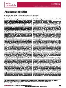
Fig. 1. Hardware Architecture
2. Target Hardware/Software Overview
The SW application runs on the external CPU, which controls the ASIC using the system bus. On top of this external CPU we run an embedded operating system (OS). Typically, we use embedded Linux. There are parts of the SW application that run inside the OS kernel, and the greater part of the software code runs in user mode. The part that runs in kernel mode is represented by the ASIC driver, which implements three main functionalities: (a) provide access to the ASIC registers (e.g., using for example, a memory mapped strategy); (b) implement the software to control the DMA module inside the ASIC; and (c) implement the Interrupt Service Routine (i.e., ISR). The SW application is a multi-threaded application. The main functionality of these threads is: (a) to write several configuration registers in the corresponding ASIC module (e.g., write the pointers from the ASIC memory where the module should read the input data to process); (b) enable the execution of the block; and (c) wait for the interruption from the corresponding module, indicating that the module has finished the execution of the data block. This user-level software code is written in C++, and it uses the STL library extensively.
2.3 Problem Statement and Requirements 2.1 Hardware Architecture The typical HW architecture of our systems is shown in Fig. 1. As we can see in this picture, we have several components all connected using the off-chip system bus. Among these components connected to the bus, we have: (a) an external CPU that is used to control the complete system; (b) external DRAM memory resources (i.e., main memory), which are used as shared memory to transfer blocks of data from software to hardware; and (c) the ASIC that implements the required image processing algorithms. As we can observe, the ASIC might have its own external DRAM memory. In addition, in Fig. 1, we give a high-level overview of the ASIC architecture, which includes two on-chip busses: the register bus and the DRAM memory bus. We have a module that is used to interact with the external system bus, and from this block we can access both onchip buses. We also have the DMA block that is used to transfer data from the main memory to the ASIC off-chip memory or vice-versa. Finally, we can observe the image processing blocks (i.e., in this example, we show two of these modules). These blocks read the data from external memory, perform the given computation, and finally write the processed data back in external memory. Each one of these modules generates an independent interrupt signal when it has finished the computation of a given block of data.
Given these HW and SW descriptions, the objective of the project is to implement a co-simulation environment that: • Minimizes the impact on the SW development – we want a non-intrusive approach into the SW development methods and tools. • Completely re-uses all the SW code running at user-level and gives a high-level leverage for the SW code that runs in kernel mode. • Gives and acceptable simulation performance to the software designers. In other words, we want to provide the SW designers a HW/SW co-simulation environment that enables a smooth integration between their current approach and this new co-development solution.
3. Overall HW/SW Co-Simulation Approach One of the main objectives in our co-simulation approach is to minimize the impact in SW development workflow. The key to accomplish this is to use different machines avoiding big environment changes. SW is developed and tested in its target environment as if the HW were available in the machine. The HW then is simulated in a different machine prepared for it, with no dependencies to the SW machine. The only requirement is having a socket library available at both machines. In Fig. 2.a the different components of the final system from SW perspective are shown. All SW communicates to
(a)
(b)
SOFTWARE
SOFTWARE
class AsicReal : IAsic
class AsicSim : IAsic
Linux Driver
Driver modified
HW/ASIC
Socket I/F
Socket I/F
HW/ASIC RTL Simulation
Fig. 2. (a) SW integration with final HW; (b) SW with HW simulation during development the ASIC through IAsic objects that will provide the functionality to communicate with the Linux hardware driver who will finally communicate with the ASIC through the system bus (e.g. PCI). This class definition provides multithread safe interface to common services offered by ASICs, like register programming, DMAs, ASIC-specific interrupt servicing, etc. while removing the initialization complexity and low level programming of the ASIC. This class is the only one interfacing with the low level Linux driver to perform the required functionality. An excerpt of IAsic class is showed here: class IAsic { virtual result writeRegister(uint32_t address, uint32_t nreg, uint32_t *value, uint32_t clientId = 0) = 0; virtual result readRegister(uint32_t address, uint32_t nreg, uint32_t *value, uint32_t clientId) = 0; virtual result writeMemory(uint32_t *address, uint32_t nreg, uint32_t *value, uint32_t clientId) = 0; virtual result readMemory(uint32_t *address, uint32_t nreg, uint32_t *value, uint32_t clientId) = 0; virtual result waitInterrupt(uint32_t interruptId, DTime timeout, uint32_t clientId = 0) = 0; };
In our co-simulation approach, this IAsic interface isolates the SW that will be reused from the one that will be leveraged and modified to communicate with the ASIC simulation machine. At the end, SW sees two different implementations of IAsic class, one that interfaces with the real HW and the other one that interfaces with a simulation of the HW. Berkeley socket I/O library allows processes from different machines connected through TCP/IP to communicate.
This library is perfect for the purposes of communicating our SW with the HW simulation process with minimum impact in SW or ASIC design workflows. Current implementation of the connection involves the use of two socket channels. One communicates the read/write to registers and memory commands to the simulation. The other communicates interrupts from HW to SW. Both communication channels need to be decoupled in order to avoid dead-locks in the resource usage.
4. Detailed Implementation 4.1 Architecture Overview The proposed architecture is split in two parts, one for the machine running real software and another running simulated hardware. These two processes are kept independent of each other by the Berkeley socket I/O library. The HW machine behaves as a server. It monitors the socket port continuously waiting for hardware access requests, such as registers or memory. In parallel, it keeps track of special hardware signals (for example, interrupts) and sends a message whenever a particular signal changes its logic state. The SW machine behaves as a client. It receives HW access requests from the SW application and forwards them to the server. In addition, it monitors interrupt messages to trigger the corresponding interrupt service routine.
4.2 The IHal Interface The IHal interface (Hal stands for Hardware Abstraction Layer), which is a pure virtual C++ class, was created to provide a unified view of the simulated ASIC and its surrounding test-bench. It resembles the low level device I/O calls available at the Linux kernel to access HW. For example, we have that the IHal implements the writeRegister32, readRegister32 and setCallback methods, which represent the user-level equivalent functions provided by the OS kernel. The setCallback function links an event with the execution of a function. In our case, it links the interrupt signal with the interrupt service routine. class IHal { virtual result writeRegister32(uint32_t address, uint32_t *value, uint32_t asicId) = 0; virtual result readRegister32(uint32_t address, uint32_t *value, uint32_t asicId) = 0; virtual result writeMemory(uint8_t *source, uint32_t destination, uint32_t numBytes, uint32_t asicId) = 0; virtual result readMemory(uint32_t source, uint8_t *destination, uint32_t numBytes, uint32_t asicId) = 0; virtual result setCallback(uint32_t aEventId, void (*handler)()) = 0; };
In addition, we observe that the IHal interface has two methods to access the external memory of the ASIC. These two methods are used to directly copy from main memory to the ASIC memory a given block of data, with-
out using the DMA module inside the ASIC. In other words, these methods are used to improve the simulation performance (i.e., we call them back-door memory access). Thus, the writeMemory and readMemory methods in the IAsic interface could be implemented using two alternatives: (a) using the DMA module of the ASIC, which takes more time; or (b) using the backdoor methods in the IHal interface, which improves performance.
4.3 Software Integration Fig. 3 shows a diagram of all the modules implemented on the SW machine. The dotted lines show the C++ interfaces defined in this architecture. The arrows show the direction in which methods or functions are called. Class AsicSim inherits from the IAsic interface. Classes HalArbiter and HalClient inherit from IHal interface. The AsicSim class implements all the methods to access registers, external memory and interrupts of the simulated ASIC. The boxes REG, DMA, ISR and FLAG represent software code written for the ASIC device driver that needs to be ported from kernel to user mode. The AsicSim
implementation wraps all this functionality and calls the appropriate IHal interface methods. The HalArbiter class is designed to handle multiple software threads that could be trying to access the same ASIC resource simultaneously. It contains semaphores that block all calling threads and lets a single thread access the socket connection. The interrupt service routine (ISR) is treated as a special thread that has higher priority than all others. Once an interrupt message is detected, the HalArbiter waits for the current thread to finish its hardware access and then allows the ISR to execute. Note that no real interrupt is generated for the host CPU. The HalClient class translates each IHal method into the corresponding message to be sent to the socket port. This implementation is not multi-thread safe (MTS) by nature, so it must have a HalArbiter attached. A separate thread inside HalClient is continuously monitoring the packets coming from the socket port. If an interrupt message has arrived, it calls a handler function that executes the interrupt service routine (ISR) in the software code.
4.4 Hardware Integration Fig. 4 shows a diagram of all the modules implemented on the HW machine. The only interface defined is the IHal, from which the class HalSim inherits. Note that all the modules shown here are running inside a mixed-language hardware simulator. Classes tagged with “sc_module” are SystemC modules. The ASIC testbench (AsicTb.v) and its internal blocks are written in Verilog. The HalServer class checks for messages at the socket port at every clock cycle of the simulated ASIC. Whenever a new message is received, it distinguishes between a register or memory access and calls the corresponding methods from the IHal interface. The HalServer also provides a method that sends an interrupt message to the SW machine. The MON (monitor) module is responsible for monitoring the interrupt hardware signal and call this HalServer method when appropriate. The HalSim class includes several modules that interact with the ASIC test-bench. The XTOR module converts the register reads and writes from transaction level to signal level, driving the ASIC ports according to a specific protocol. The MEM module handles the memory reads and writes by directly accessing the memory model in the testbench. That is, the MEM module is used to instantaneously move a block of data from main memory to the ASIC memory without using the DMA block of the ASIC. In addition, in a typical ASIC testbench there are other functional models that model the behavior of external devices necessary for the ASIC to work correctly (e.g., clock and reset generation).
Fig. 3. Architecture on the SW machine
socket
class HalServer
IHal sc_module HalSim : IHal sc_module mem
sc_module xtor
sc_module mon
MEM
XTOR
MON
ASIC
INT
AsicTb.v HW machine
Fig. 4. Architecture on the HW machine
5. A Case Study: LINXS Project We have implemented the three main components of this proposal (i.e., HalSever, HalClient and HalArbiter) using C++. In addition, we have applied this methodology to the Linxs pilot project.
5.1 Project Description For this pilot project we selected a representative ASIC design called BeagleLite. It has a PCI interface, SDRAM memory controller plus several modules that perform image processing functions. The complete HDL (i.e. verilog) model for BeagleLite and its associated Micron DRAM memory are available in the HW simulation testbench. With the SystemC implementation on top of the HDL, the simulation is ready to start the communication with the software machine. All the hardware simulations run in a Pentium PC with Linux Red Hat 8.0.and using Cadence NC-Sim. The multi-threaded SW application runs in several Linux versions (Red Hat 7.1, 8.0 and 9.0).
5.2 Simulation Performance Numbers Since almost all HW/SW interactions are done or initiated using register accesses, we have measured the simulation performance of a register read operation. In order to per-
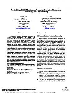
form this measurement, we have coded a simple application that runs 2000 times a read register operation. We have obtained that a read register takes around 3.7ms. This time includes: (a) the time required to send the packed with the request from the SW to the HW machine; (b) the time required by the verilog simulator to actually run the cycle-accurate access to the ASIC register; and (c) the time required to send the read return value from the HW machine to the SW machine. It is important to mention that we have also performed experiments where we only measured the cycle-accurate read register simulation time (i.e., traditional RTL-based simulation approach). When we compared these numbers with the performance numbers obtained when we use the approach based on two machines (i.e., socket-based interface), we have observed that the read register cycleaccurate simulation time is the main contributor of the complete read operation. In other words, the socket interface introduces an overhead that is below 10%. Then, we executed a second set of experiments, which consists on actually running a multi-threaded SW application. In this case, a thread implements the following steps: (a) moves, the data to be processed from the main memory to the ASIC simulated memory using the memory backdoor; (b) programs all the required registers in the ASIC block, in order to enable that block to perform the image processing algorithm; (c) waits for the interruption of the ASIC block; and (d) finally reads the processed data from the ASIC simulated memory back into the main memory. At that moment, the SW code can check that both HW and SW worked properly. This mechanism could be applied to three different image processing modules, and for each module, we have carried out four experiments, where we have changed the size of the input image. That is, we wanted to see the simulation performance numbers (i.e., simulation time) when we increase the input data size (e.g., 1Kbyte, 10Kbyte, 100Kbyte and 500Kbyte). Fig. 5 shows the obtained results, where we show two possible configurations: (a) in configuration one, both the multi-threaded SW application and the HW simulator run on the same machine; and (b) in configuration two, the Simulation Time (seconds) Data Size
HW and SW running in the same machine
HW and SW running in different machines
1Kbyte
1.02
0.42
10Kbyte
2.95
2.51
100Kbyte
23.66
22.61
500Kbyte
115.15
112.30
Fig. 5. Simulation time when increasing the input data size
SW application runs on one machine and the HW simulator runs in a different machine. In these experiments, we are assuming input images with 8bits/pixel. We can observe that it takes about 23 seconds to simulate an input image of 512 rows and 256 columns (i.e., 100Kbyte of data size). The main objective of these results is to show that the obtained simulation times are acceptable for the initial SW development (i.e., larger images might be processed also by our system, during the nightly regressions of SW code). Moreover, it is interesting to observe that the configuration that uses two machines improves the results obtained when we use a single machine. The reason for these results is because in the configuration that uses a single machine, both processes (i.e., SW application and HW simulator) must compete for the CPU utilization (i.e., the SW application takes CPU time to the HW simulator, which is more critical and time consuming process). In the second configuration where we use two machines, the HW simulator has a whole CPU to run the HW simulator.
7. Conclusions
6. Previous Work
References
There are other alternatives to early test SW and HW integration but with different approaches that can fulfill different needs: • Use FPGA for ASIC prototyping [3]. This is a good solution in terms of simulation performance (i.e., it could run at speed), but it has the drawback that there are some modules of the ASIC (i.e., ASIC vendor-specific hard-macros) that could not be prototyped on FPGA’s. • C modeling. It exist the possibility to create highlevel models (e.g., C/C++) of the ASIC that can be later on integrated with your SW. However, this means having two models of the ASIC, one in verilog HDL and a second one in C/C++. This is costly in terms of development effort and the use of a C/C++ model could hide HDL bugs. • Co-simulation [6][7]. Third party co-simulation tools have proved to be successful to integrate SW in certain SoC platforms but they are limited to embedded processors (ARM, MIPS). They are also limited in supporting large size SW/OS like Linux. That is, it is totally unacceptable in terms of performance to run a complex SW application on top of an Instruction Set Simulator (ISS). Our approach is new in giving a solution that combines the flexibility of an FPGA prototype, supporting virtually any CPU/OS combination that enables socket connection, and the ability to use the final ASIC design that will be used for sign-off. It requires very low effort to integrate as it reuses the whole ASIC simulation test-bench, and it maintains the SW development environment with very few modifications.
[1] [2] [3] [4]
It is becoming increasingly evident that HW/SW cosimulation should play a key role in the development of future SoC platforms, since it reduces the product development time and reduces de design costs. In this paper, we have introduced one of the main issues that is stopping the widespread use of HW/SW cosimulation in the industry. In our opinion, the required HW/SW co-simulation solution must be non-disruptive in the current methodologies and tools used by the SW designers. This paper presented a software-friendly HW/SW co-simulation approach, where we can completely re-use the SW application running at user-level and achieve a high-level of leverage for the code running in kernel. We have applied this methodology to a real case study, where we have used an ASIC that implements image processing algorithms. Despite of using a cycle-accurate model of the ASIC, the simulation performance has been shown to be acceptable for SW development.
http://www.cadence.com http://www.mentor.com http://www.xilinx.com CODES+ISSS’03 Panel on System Level Design Tools, http://www.ece.uci.edu/codes+isss/ [5] Mojy Chian, “Economics of SOC Development: How can we make this a profitable endeavor?”; Invited talk at CODES+ISSS’03 [6] Luca Formaggio, Franco Fummi, Graziano Pravadelli, ”A Timing-Accurate HW/SW Co-simulation of an ISS with SystemC”. CODES+ISSS’04. [7] Shinya Honda, Takayuki Wakabayashi, Hiroyuki Tomiyama, Hiroaki Takada, “RTOS-Centric Hardware/Software Co-simulator for Embedded System Design”. CODES+ISSS’04 [8] Donald E. Thomas , Jay K. Adams , Herman Schmit, “A Model and Methodology for Hardware-Software Codesign”, IEEE Design & Test, v.10 n.3, Jul. 1993 [9] Giovanni De Micheli, “Computer-Aided HardwareSoftware Codesign”, IEEE Micro, v.14 n.4, Aug. 1994 [10] Matthias Bauer, Wolfgang Ecker, “Hardware/software cosimulation in a VHDL-based test bench approach”, Proc. of the 34th Conf. on Design automation Conference, 1997