Solution to Close-in Fault Problem in Directional Relaying. A. K. Pradhan and P. Jena. AbstractâDirectional relays use voltage as the polarizing quan- tity.
1690
IEEE TRANSACTIONS ON POWER DELIVERY, VOL. 23, NO. 3, JULY 2008
Solution to Close-in Fault Problem in Directional Relaying A. K. Pradhan and P. Jena
Abstract—Directional relays use voltage as the polarizing quantity. When three-phase faults occur close to the relay bus, the available voltage becomes nearly zero and this creates a problem in estimation of the fault direction. The capacitor coupling voltage transformer subsidence transients add to this problem. The memory voltage used as the polarizing quantity at these situations is a compromise. This paper highlights these issues and proposes a simple solution using the power-flow direction in addition to other information. The performance of the technique is evaluated through simulation in Power System Computer Aided Design.
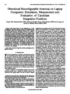
Fig. 1. Two-source system.
TABLE I RESULTS ON DIRECTIONAL RELAYING
Index Terms—Digital relay, directional relay, fault, phasor estimation, subsidence transient.
I. INTRODUCTION
D
IRECTIONAL relaying is widely applied in line protection to enhance the sensitivity and reliability of the protection schemes [1]–[4]. Current and voltage phasors or the derived sequence components are used to estimate the fault direction where voltage is used as a polarizing quantity. When three-phase faults occur near the sensors, the available voltage to the relay becomes substantially low and it places a challenge in correct voltage phasor estimation. Due to subsidence transients with the capacitor coupling voltage transformer (CCVT) in these situations, the performance of the directional relay is not reliable. As a measure, the low-voltage polarizing quantity is substituted by a suitable memory signal, such as prefault positive-sequence voltage [1], [3]. However, this approach is also not reliable which is demonstrated in the following example. A 132-kV, 50-Hz three phase two-source system as shown in Fig. 1 is simulated using Power System Computer Aided Design (PSCAD). A directional relay is located at bus B and the power-flow direction at a situation is from bus A to bus C. Three-phase faults are created at the Fx and Fy sides of the relay and the results are shown in Table I (phasors computed through one-cycle discrete Fourier transform (DFT) with 1-kHz sampling rate). This indicates that the phase-angle difference between positive-sequence fault current and voltage is positive for Fx side faults and negative for Fy side faults. This rule is applied in such directional relaying with the angle difference being rerad. stricted to Next, the three-phase fault is created in the Fx side very close to the relay bus B. The voltage waveforms are shown in Fig. 2 where the system voltage collapses but corresponding CCVT outputs still show voltage. The results of different phasors are provided in Table II where it is observed that if the low voltage at the relay bus is considered as the polarizing quantity, the angle difference is negative for the Fx case and positive for the Fy case
Manuscript received December 6, 2007. Paper no. PESL-00137-2007. The authors are with the Department of Electrical Engineering, Indian Institute of Technology, Kharagpur 721302, India. Digital Object Identifier 10.1109/TPWRD.2008.923149
Fig. 2. (a) Line voltage during close-in fault at the relay bus. (b) CCVT output during a close-in fault.
which contradicts the earlier result in Table I. On the other hand, if the prefault positive-sequence voltage becomes the polarizing voltage, the results in the last column are in accordance with the rule, providing accurate direction estimation. The power-flow direction is then changed to bus C to A and similar faults are created for the Fx and Fy sides. The phasor results are provided in Table III where it is observed that with the prefault voltage as the polarizing quantity, for faults in the Fx side, the angle difference is negative and for the Fy side, it is
0885-8977/$25.00 © 2008 IEEE
IEEE TRANSACTIONS ON POWER DELIVERY, VOL. 23, NO. 3, JULY 2008
1691
TABLE II RESULTS OF THE CLOSE-IN FAULT (POWER-FLOW DIRECTION A TO C)
TABLE III RESULTS OF THE CLOSE-IN FAULT (POWER FLOWS FROM C TO A)
Fig. 4. Different positive-sequence currents when power flows from bus C to A. (a) Fault at Fx. (b) Fault at Fy.
Fig. 3. Phasor diagram showing different positive-sequence currents I and —fault components are only and I and I —fault currents (including load I current) when power flows from bus A to C. (a) Fault at Fx. (b) Fault at Fy. Fig. 5. Flow diagram for the algorithm.
positive which is again contradictory. A solution to this problem is proposed in the next section.
TABLE IV CLOSE-IN FAULT (POWER FLOWS FROM A TO C)
II. PROPOSED SCHEME It is observed that the decision of conventional directional relaying is not consistent for close-in faults when the prefault voltage becomes the polarizing quantity. Numerous cases were simulated and it was found that for one direction of power flow, such polarizing quantity provides a correct decision but not for the reverse direction of power flow. This is due to fact that the fault current takes a different position when the power-flow direction changes. This is clearly evident from the phasor diagrams in Figs. 3 and 4. Positive-sequence fault current and prefault voltage phasors for faults at Fx and Fy sides are available in Fig. 3. It is observed that the corresponding and are of positive and negphase-angle differences ative values, respectively, for the power-flow direction from bus and for the power-flow diA to C. On the other hand, rection from bus C to A (Fig. 4) are negative and positive values, respectively. Thus, the phasor diagrams indicate that to obtain angle should be multiplied by the correct fault direction, the
in the case of reverse power flow; from bus C to A. This provision is included in the proposed directional relaying scheme which is shown in Fig. 5. To demonstrate the performance of the approach, three-phase close-in faults are simulated at the Fx and Fy sides with a power-flow direction from A to C. The result for the case is provided in Table IV and it is found that it has correctly identified the direction. Similarly correct decisions are observed for the power-flow direction from C to A as presented in Table V.
1692
IEEE TRANSACTIONS ON POWER DELIVERY, VOL. 23, NO. 3, JULY 2008
TABLE V CLOSE-IN FAULT (POWER FLOWS FROM C TO A)
being applied. It proposes a solution for such low-voltage situations by using the power-flow direction as additional information, which is being verified through simulations. REFERENCES
III. CONCLUSION This letter addresses issues related to a close-in fault in directional relaying when memory polarization (prefault voltage) is
[1] A. G. Phadke and S. H. Horowitz, Power Systems Relaying. Taunton, U.K.: Research Studies Press, 1992. [2] D. Birla, R. P. Mahwswari, and H. O. Gupta, “A new nonlinear directional overcurrent relay co-ordination technique, and banes and boons of near-end faults based approach,” IEEE Trans. Power Del., vol. 21, no. 3, pp. 1176–1182, Jul. 2006. [3] J. Roberts and A. Guzman, “Directional element design and evaluation,” [Online]. Available: www.selinc.com/techpprs/6009.pdf., 1994. [4] A. K. Pradhan, A. Routray, and G. S. Madhan, “Fault direction estimation in radial distribution system using phase change in sequence current,” IEEE Trans. Power Del., vol. 22, no. 4, pp. 2065–2071, Oct. 2007.