2184
IEEE TRANSACTIONS ON VERY LARGE SCALE INTEGRATION (VLSI) SYSTEMS, VOL. 20, NO. 12, DECEMBER 2012
Standard Cell Like Via-Configurable Logic Blocks for Structured ASIC in an Industrial Design Flow Hui-Hsiang Tung, Rung-Bin Lin, Member, IEEE, Mei-Chen Li, and Tsung-Han Heish
Abstract—A structured application-specific integrated circuit (ASIC) has prefabricated yet configurable logic block arrays. We investigate some important via-configurable logic block (VCLB) design issues. We particularly focus on creating a VCLB layout that enables a standard cell like design. We propose the VCLB composability concept which enables us to use multiple VCLB instances to realize a complex logic gate. We devise four new VCLBs and construct several cell libraries based on these VCLBs. We develop a design flow mostly using industrial design tools and propose a method to evaluate VCLB viability. The experimental results show that a medium-grained VCLB that realizes a rich set of logic functions attains the best performance. Index Terms—Regular fabric, standard cell, structured application-specific integrated circuits (ASICs), via-configurable logic block.
I. INTRODUCTION
A
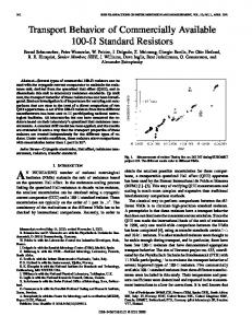
STRUCTURED application-specific integrated circuit (ASIC) has prefabricated yet configurable logic block (CLB) arrays and possibly a regular routing fabric laid over CLB arrays [1]–[5]. It may also contain pre-diffused or customized IPs and programmable I/Os [3]. A CLB can be via or metal-configurable (programmable). A via-CLB (VCLB) is less flexible but uses fewer customizable mask layers. The routing between CLBs can also be via or metal-configurable. Via-configurable routing is carried out on a regular routing fabric consisting of repetitive predefined patterns on higher metal layers [6]–[9]. It also needs fewer customizable mask layers. In terms of cell and routing configurability, as shown in Fig. 1, we can define a design style programmability spectrum [10]. One end of the spectrum is the cell-based ASIC with non-programmable cells and metal programmable routing fabrics. The other end is the field-programmable gate array (FPGA) with SRAM-based programmable cells and routing fabrics. The gaps between these two ends [4] are manifested by the differences in performance, area, power, non-recurring engineering (NRE) cost, design turn-around-time, etc. The structured ASIC embraces a large mid-section of the programmability spectrum. It achieves higher performance than Manuscript received March 27, 2011; revised July 30, 2011; accepted September 08, 2011. Date of publication December 05, 2011; date of current version August 02, 2012. This work was supported in part by the National Science Council, Taiwan, under Grant NSC 96-2221-E-155-064-MY3. The authors are with the Department of Computer Science and Engineering, Yuan Ze University, Chung-Li, 320 Taiwan (e-mail:
[email protected]. edu.tw;
[email protected];
[email protected]; s976049@mail. yzu.edu.tw). Color versions of one or more of the figures in this paper are available online at http://ieeexplore.ieee.org. Digital Object Identifier 10.1109/TVLSI.2011.2170712
Fig. 1. Programmability spectrum of design styles.
FPGA yet incurs a lower NRE cost than the ASIC. It fills the gaps between the cell-based ASIC and FPGA designs. As mask tooling costs keep increasing exponentially [11] and re-spin percentage remains high for designs using an advanced process technology [12], the structured ASIC can provide an economic solution to rapid prototyping and low to medium volume production with lower NRE costs than ASIC. Its prefabricated substrate and predefined regular wiring patterns are conducive to achieving a higher manufacturing yield. A. Current Status and Future Outlook The structured ASIC was an active research area and a viable technology for chip implementation some years ago. A survey [13] made in 2005 showed that about 13% of designers, down 1% from 2004, would consider using the structured ASIC for their designs. After several years of relentless effort, structured ASIC vendors have developed a variety of products with different technology features. Table I shows the programmability choices and the granularity of CLBs adopted by some vendors [2], [3], [5], [14]–[27] and research groups [1], [7], [28], [29]. This is by no means an exhaustive list. The second column is about CLB granularity. It can be fine-grained, medium-grained, or coarse-grained. Here, CLB granularity classification is based on whether the transistors in a CLB are more than enough for implementing the complex logic functions in a typical cell library. The third column shows the cell and routing fabric programmability choices. The choices can be metal, via, or SRAMbased lookup table (LUT) programmability. The last column shows whether we can configure the same transistors in a CLB to implement a combinational logic cell or a sequential element. As one can see, most vendors employ metal programmable cells and routing fabrics. Such a choice incurs the least performance penalty and tool development effort but will need more customizable masks.
1063-8210/$26.00 © 2011 IEEE
TUNG et al.: STANDARD CELL LIKE VIA-CONFIGURABLE LOGIC BLOCKS FOR STRUCTURED ASIC IN AN INDUSTRIAL DESIGN FLOW
TABLE I PROGRAMMABILITY CHOICES
Although the momentum for structured ASIC has subsided as many vendors like LSI, NEC, LightSpeed Logic ceased to support structured ASIC, some vendors still take advantage of the structured ASIC to rapidly bring their products to market. For example, Faraday Technology Corporation has used its media application platform to produce more than 20 tapeouts, each of which has an engineering change order (ECO) turnaround time less than two weeks [23]. In the future, as long as the ASIC NRE cost and the gaps between ASIC and FPGA remain large, the structured ASIC can still be a viable technology. The continuous use of 193 nm lithography for 32/22 nm technology nodes will further play a more important role in revitalizing structured ASIC adoption. Structured ASIC layout regularity will not only simplify the set of restricted design rules [30] and reduce the mask tooling shot count, but also greatly enhance the effects of various reticle enhancement techniques for improving manufacturability [31]–[34]. It is encouraging to see that Jhaveri et al. [32], [33] are able to achieve comparable timing and area utilization for an ARM926EJ implementation exploiting only a small set of layout primitives for forming regular layouts, with respect to an implementation based on a commercial 65-nm standard cell library. As such, structured ASICs could again become a viable design technology. B. Our Work and Contributions In this work, we focus on via-configurable structured ASIC because it employs fewer customizable masks than metal-programmable structured ASIC. It was also least explored and understood in the past. To create a viable structured ASIC technology, the via-configurable logic block (VCLB) should be designed to leverage existing tools to establish a structured ASIC design flow known to most designers. We should avoid creating new design tools because tool development is time consuming and expensive. Based on logic function configurability, a structured ASIC is more like an FPGA. However, in terms of mask
2185
programmability, a structured ASIC is more like a standard cell design. From the mask programmability viewpoint, via-configurable structured ASICs are more amenable to a standard cell like design flow. In such a flow, a VCLB should be made to realize important logic functions in a typical standard cell library so that logic synthesis for the structured ASIC can be done just like that for standard cell designs. Physical design except routing can also be performed using existing tools for standard cell designs. The same is true for physical verification, timing analysis and optimization. A standard cell like design flow has several advantages. First, standard cell designers who seek to lower NRE costs would be more willing to consider structured ASICs due to similarity in design flow. Second, standard cell design tools are more amenable to mask programmable designs so that the timing, area and performance advantages of mask programmability can be fully explored. Third, the test methodologies employed for standard cell designs can be used without any change. In view of these points, a VCLB should be made to enable standard cell designs. Note that the term standard cell like referred in this article is used to emphasize that the layout style of our VCLBs is similar to the one used for designing standard cells. Hence, one can design a via-configurable structured ASIC using a similar design flow as that employed by conventional standard cell designs. We first discuss some important issues about developing a VCLB that enables a standard cell like structured ASIC. Many of these issues were mentioned or even elaborated individually in the past. A few of them such as VCLB composability are newly explored in the present work. However, it is the present work that assembles them together so that they can be more fully considered during the VCLB design process. We describe how we design a VCLB by taking almost all of these issues into account, specifically how we determine VCLB granularity, VCLB dimensions, transistor sizes, and VCLB wire planning in support of power/ground distribution, signal routing and composability. Composability allows us to use a fine or medium-grained VCLB to implement a complex logic gate. In the past, almost no work except [7] delved into VCLB wiring problems. Ran and Marek-Sadowska [7] investigated how predefined wires in a VCLB should be laid out to facilitate logic function realization using series-parallel connected transistors. In the present work, we develop four new VCLBs and five cell libraries. For the purpose of comparison, we also implement three cell libraries based on the work done in [28], [35], and [36]. We also establish a structured ASIC design flow starting from logic synthesis to post-routing timing analysis using industrial standard cell design tools. We also propose a method to evaluate the performance of a cell library by pushing the design delay envelope, i.e., finding its achievable smallest longest path delay. Experimental results based on the TSMC 0.18- m process technology show that with respect to the smallest longest path delay of the designs obtained using an industrial standard cell library [37], designs that use the above structured ASIC libraries on average achieve a longest path delay ratio ranging from 1.15 to 2.34, a core area ratio ranging from 2.51 to 9.25, and a power dissipation ratio ranging from 1.30 to 2.85. We find that our medium-grained VCLBs, each of which enables us to realize a rich set of logic functions, attain the best performance.
2186
IEEE TRANSACTIONS ON VERY LARGE SCALE INTEGRATION (VLSI) SYSTEMS, VOL. 20, NO. 12, DECEMBER 2012
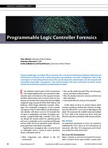
Fig. 2. VCLB. Fig. 3. VCGA in [7].
The rest of this paper is organized as follows. Section II reviews some related works and discusses some important VCLB design issues. Section III presents how we devise a standard cell like VCLB. Section IV presents the VCLBs and cell libraries designed in this work. Section V introduces our design methodology. Section VI gives some experimental results. The last section draws a conclusion and discusses future work. II. BASICS OF VIA-CONFIGURABLE LOGIC BLOCK A VCLB contains some prefabricated transistors and metal wires and predefined wires up to certain layer. We can configure some vias between the prefabricated wires and predefined wires to realize a logic cell. For example, Fig. 2 shows a VCLB with three prefabricated transistor pairs, some prefabricated M1 wires, and some predefined M2 wires. We use twelve vias between M1 and M2 to configure this VCLB into a NAND3. These vias constitute a via map of NAND3. We name a via at the intersection of horizontal track and vertical track . The two vias and connect the sources of the three transistors to VDD. and connect their drains together. and connect the drains of and transistors together. connects the source of the right-most transistor to GND. Input and output pins are laid on M2 in the center region. They are connected to the logic gate by , and , respectively. In the following, we will review some existing VCLBs and discuss some issues about creating a VCLB. A. Related Work As shown in Table I, structured ASIC vendors all have their own CLBs of different granularities but reveal little information about the circuit and layout designs of these CLBs. In academia, Ran and Marek-Sadowska [7], [9] proposed a coarse-grained VCLB, called VCGA, whose transistors can be connected serially or in parallel. The team led by Pileggi [1], [6], [8], [38] proposed a number of coarse-grained VCLBs based on -input LUT and its variants. The group led by Fujino [28] proposed VPEX2 architecture based on via-configurable Exclusive OR and inverter. The group led by Khatri proposed via-configurable NAND2 [35], PLA [39], and ITE-cell [40]. Some VCLBs are designed specifically for improving manufacturing yield [35], [41], [42]. Chen et al. [36] presented a standard cell like viaconfigurable 3-LUT. Chau et al. [29] proposed a MUX-based
VCLB which can be configured into some 2/3-input functions or a latch using one programmable metal layer. Recently, Baek et al. [43] proposed using selective pattern masks to customize CLBs into different logic functions. In the past, we proposed a VCLB whose layout design tailored to address some issues discussed in Section II-B [10]. This paper is partially based on this previous work. In general, we can classify VCLBs into three categories in terms of how they are configured to realize logic functions. First, a VCLB can be an FPGA-like LUT, called LUT-based VCLB. LUT-based VCLBs proposed in [1] can be laid out in a way similar to standard cells. Its layout style enables simple power/ground (P/G) distribution. P/G lines between adjacent cells can be abutted and P/G stripes using higher metal layers can be easily deployed to form a P/G network. A problem of LUT-based VCLBs is that each LUT is usually accompanied by a flip-flop. If flip-flops are not used as frequently as LUTs, the transistor utilization in VCLBs will be low. This problem can be solved by making an LUT whose transistors are also wired to realize a flip-flop [36]. The second category of VCLBs is based on PLA structure [39], [44]. PLA enables two-level logic function implementation, but each PLA cell still needs to be accompanied by flip-flops for implementing a sequential design. The third category of VCLBs [7] uses series-parallel structures to implement either combinational logic gates or flip-flops. Since our work is closely related to this kind of VCLB, we will detail the work proposed in [7]. The VCLB proposed in [7] is called via-configurable gate array (VCGA) as shown in Fig. 3. Each VCGA has four basic logic elements (BLEs), each of which consists of a via configurable cell called ViaCC (VCC for short) and two via configurable cells called INVAs. An n-VCC consists of n pairs of P-N transistors. A 5-VCC is specially presented in [7]. All of the layers below M1 are prefabricated and the M2 layer contains only predefined mask patterns. The M2 P/G lines run horizontally in parallel with diffusions and the M1 wires run vertically to the M2 wires. Only vias between M1 and M2 can be used to define the logic function of a 5-VCC. A 5-VCC can implement five or fewer input functions. Since transistors can be only connected serially or in parallel, a 5-VCC can realize only a limited number of logic functions [7]. For example, among the 2-input
TUNG et al.: STANDARD CELL LIKE VIA-CONFIGURABLE LOGIC BLOCKS FOR STRUCTURED ASIC IN AN INDUSTRIAL DESIGN FLOW
functions, a 5-VCC realizes only NAND and NOR. Hence, INVA is introduced to mitigate this problem. An INVA has four pairs of P-N transistors which can be used to implement inverters, XOR/XNORs, multiplexers, etc. It has three diffusion strips for each type of transistors. P/G lines in an INVA are run horizontally in M1. One important feature of a VCGA is that it can be also configured to realize a flip-flop. However, there are a few problems not addressed in [7]. For example, a chip based on VCGA will have a complicated yet highly resistive P/G network due to using a large number of vias for connecting the short P/G lines in a VCGA. Note that the P/G lines in a 5-VCC and an INVA are not located on the boundaries so that abutting rows to make wider P/G lines is not possible. Such a layout does not allow a via to drop freely from an M3 P/G stripe to an M1 P/G line because a short to M2 signal wires in INVAs may occur. This further complicates and limits the P/G network distribution. All of these problems prevent the VCGA from enabling a standard cell like design. Another problem with VCGA is that the fourth quadrant of a BLE does not have any transistors. The VCLBs proposed in our work do not have the above problems. B. Basic Design Issues About VCLBs Although significant progress in VCLB research was made in the past, further VCLB studies are required to make via-configurable structured ASIC more viable. In the following, we will discuss some important issues related to creating a VCLB that enables a standard cell like structured ASIC. The most unique characteristic of the logic gates in a cell library based on a standard cell like VCLB is that all of the logic gates are implemented using the same underlying VCLB. This differs considerably from the way a logic gate in a conventional standard cell library is designed. The basic design issues listed below are by no means exhaustive. Note that some of these issues are individually mentioned or discussed in the previous work. Design Tool Support: This might be the first issue yet to be dealt with for designing a VCLB. Engineering a VCLB, especially its layout, should facilitate leveraging as many existing tools as possible to establish a structured ASIC design flow. Any missing link in a design flow could mean a costly overhead. Currently, standard cell and FPGA are two major design styles. As it was elaborated in Introduction section, via-configurable structured ASIC is more amenable to standard cell designs. We will hence establish a structured ASIC design flow using mostly existing standard cell design tools. Logic Functions Realized by a VCLB: How many logic functions should a VCLB be able to realize? Is it important to provide a VCLB that can implement all -input logic functions? Basically, we can find an answer to these two questions based on a standard cell library. A typical standard cell library does not normally contain all 3-input logic functions, not to mention all 4-input logic functions. Our suggestion is that a VCLB should be designed to realize most of the logic functions found in a typical standard cell library. Number of Predefined Metal Layers in a VCLB: Using more predefined metal layers increases routability within a VCLB and could potentially result in a smaller VCLB. However, this requires more customizable via layers and thus increases the NRE
2187
cost. Using two or three predefined metal layers is typical. Here, a prefabricated metal layer is counted as a predefined layer. VCLB Granularity: This is about the number of transistors used to form a VCLB. Determining such a number is a difficult task [38]. The granularity can be fine-grained, medium-grained, or coarse-grained. The lines drawn between them are not universally agreed among designers. We also tend not to draw the lines clearly. However, a coarse-grained VCLB would mean more than enough transistors in it to implement many more complex logic functions not found in a typical cell library. On the other hand, a fine-grained VCLB could only realize a handful of logic functions found in a typical cell library. The VCLB granularity is an important factor that would greatly influence chip area and performance. It also influences whether a packing tool should be developed for a VCLB [7], [45]. VCLB Composability: Composability is about the capability of abutting multiple VCLB instances to realize a more complex logic function. It is defined not only based on the functional point of view but also from the layout realization point of view. Hence, we define composability as that a composable VCLB is the one that uses wires only allocated to the VCLB instances to pass signals from one VCLB instance to its adjacent instances and the wiring patterns inside any two VCLB instances should be the same. Composability is specifically needed when a finegrained VCLB is employed to create a cell library with a rich set of logic functions. Normally, predefined wires on the left and right boundaries of a VCLB are specifically engineered to enable composability. To the best of our knowledge, the present work is the first to use composability to design complex logic functions with multiple instances of a fine or medium-grained VCLB. Unified Sequential and Combinational VCLB: This is about the capability of configuring the same transistors into combinational logic functions or a flip-flop [7], [10], [36], [45]. Such a capability enables us to save chip area. However, laying out the predefined wires inside a VCLB will become more complex. This might increase VCLB area slightly. Since saving considerable chip area can be expected, a VCLB layout should be designed to support this capability [36]. More importantly, with this capability we do not have to determine the number of flip-flops that should be set aside on a chip beforehand. This capability also enables us to freely relocate logic elements. Since the number of flip-flops used in a design is determined by a logic synthesis tool and their locations are determined by a placer, we do not need a predefined clock network on a standard cell like structured ASIC. Hence, we can use a clock network synthesis tool for standard cell designs to customize a clock network for each structured ASIC design. VCLB Relocation: This is about whether a logic gate or an IP can be placed at an arbitrary location on chip substrate. It is an important feature of a structured ASIC which is comprised of only VCLB instances of the same type. For a structured ASIC which employs two or more types of VCLB, relocating a VCLB to a place occupied by a VCLB of different type is prohibited. Since there is a problem in determining the portions of different types of VCLB and their placement on the substrate, we consider the structured ASIC that uses only one type of VCLB. This will enable us to relocate a logic gate or an IP [17] freely to an-
2188
IEEE TRANSACTIONS ON VERY LARGE SCALE INTEGRATION (VLSI) SYSTEMS, VOL. 20, NO. 12, DECEMBER 2012
other place on a chip so that a typical standard cell placer can be employed for placement. Enabling SRAM Block Implementation: This issue considers whether a VCLB can be effectively used to synthesize an SRAM block. The same VCLB should be used to realize an SRAM cell, but also all of the peripheral circuits such as row decoder, column multiplexer, sense amplifier, etc. Here, we have two options. First, we can use the same VCLB for implementing combinational logic gates and an SRAM cell. In this way, the so-generated SRAM block will be relocatable, i.e., like an SRAM block in a standard ASIC being freely placed on a chip. Another advantage is that the size of an SRAM block need not be determined beforehand. However, we could end up with a larger VCLB. Moreover, the timing performance of logic gates may be compromised by some particular requirements such as properly sizing the six transistors in an SRAM cell. The second option is that we can use one VCLB for logic implementation and another for SRAM blocks. Hence, we can optimize the timing and area of both VCLBs individually. However, we face a problem of having to determine the size and location of an SRAM block beforehand. In this work we do not consider this issue, but we can reengineer a VCLB such as SLVC5P by properly sizing its transistors to implement a six-transistor SRAM cell. However, one should address this issue right from the beginning. Compliant to Design Rules for Manufacturability: This issue concerns whether the layout patterns on a certain layer form a regular structure. We may have to add some dummy layout objects to form a regular layout structure. A regular layout structure should have a proper pitch. We should also properly align the regular layout structures on two adjacent layers. The 0.18m VCLB layout designs presented in this paper do not consider this issue. However, layout designs based on a technology node smaller than 65 nm should consider this issue. Library Development Efforts: The library development effort is proportional to the number of cells in a library. A cell library should include a variety of commonly used logic gates with different driving capabilities. Basically, we should minimize library development effort regardless of VCLB granularity. However, doing so should not worsen any design quality indices. The above issues are related to each other. The basic logic functions realized by a VCLB depend on VCLB granularity. What we mean by a basic logic function is a logic function that has a template in a typical standard cell library. A coarse-grained VCLB can be configured to implement many basic logic functions. A fine-grained VCLB can realize a few simple logic functions, but its composability enables us to form more complex logic functions using multiple VCLB instances. VCLB composition uses only the programmable via layers and predefined wires belonging to VCLB instances for implementing a logic function. A fine-grained VCLB will have better transistor utilization. However, more area penalty is paid for isolating VCLB instances from each other because more fine-grained VCLB instances are used to implement the same design. Although a single coarse-grained VCLB can implement more logic functions, it may incur a large area penalty due to poor transistor utilization. This problem can be mitigated by packing several simple logic functions into a VCLB, but doing so would complicate the library development task and require developing a
Fig. 4. SLVC5P stick diagram.
Fig. 5. SLVC5PM3 stick diagram.
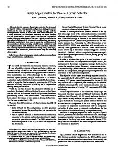
good packing tool. Interestingly, logic packing and composability are somewhat opposite to each other. If a VCLB contains only a few transistors, we need composability for assembling several VCLB instances into a complex logic gate and hence do not require logic packing. If a VCLB contains more than enough transistors for implementing a complex logic gate, we require packing several logic functions into a VCLB instance to improve transistor utilization and hence do not need composability. Poor transistor utilization in a coarse-grained VCLB could also occur if each VCLB also includes a flip-flop but the flip-flop is not used in the design. III. DESIGNING OF STANDARD CELL LIKE VCLBS In this section we describe how to design a VCLB that enables standard cell like structured ASIC designs. Determining VCLB granularity and crafting VCLB layout are two most important tasks. We will consider most of the issues discussed in Section II-B, especially a wiring plan for enabling VCLB composability and implementation of versatile logic functions. In the past, issues about VCLB layouts were mostly ignored. However, Ran and Marek-Sadowska [7] did investigate how predefined wires in an n-VCC should be crafted to facilitate realizing the logic functions formed by series-parallel connected transistors. Here, we design four VCLBs called SLVC5P, SLVC5PM3, SLVC5Pv2, and SLVC2P. SLVC5P, SLVC5PM3, and SLVC5Pv2 each have five pairs of P-N transistors whereas SLVC2P has two, as shown in Figs. 4–7, respectively. Since poly, M1 and M3 are stacked one over another, for clarity they are drawn with a small offset relative to each other. The layouts of these VCLBs are simple and regular. The polysilicon wires are unidirectional. We can add dummy polysilicon wires to form a uniform layout and properly tune their spacing and
TUNG et al.: STANDARD CELL LIKE VIA-CONFIGURABLE LOGIC BLOCKS FOR STRUCTURED ASIC IN AN INDUSTRIAL DESIGN FLOW
2189
Fig. 6. SLVC5Pv2 stick diagram.
Fig. 8. Layout of SLVC5P.
Fig. 7. SLVC2P stick diagram.
TABLE II LOGIC FUNCTIONS IN A TYPICAL STANDARD CELL LIBRARY
width to avoid forming a forbidden pitch. The same can be done for metal wires, especially for M1 wires. Hereon, a VCLB will refer to a template used for realizing a logic function. It will also denote an instance of itself if no confusion arises. VCLB instances denote several instances of a VCLB. A. VCLB Granularity We determine VCLB granularity by delving into a typical standard cell library [37]. We find that the number of inputs per logic gate ranges from one to six as shown in Table II. Most of the cells have two to four inputs. Since an input is normally connected to a pair of P-N transistors, we determine that our SLVC5P, SLVC5PM3, and SLVC5Pv2 use five pairs of P-N transistors. The transistor floorplan for the SLVC5PM3 is similar to that of the SLVC5P, but SLVC5PM3 uses one more predefined metal layer. As a result, the SLVC5PM3 has a smaller footprint. SLVC5Pv2 has two diffusion strips and uses one fewer vertical track than SLVC5P does. To take advantage of VCLB composability, the SLVC2P is designed to be a fine-grained VCLB with only two pairs of P-N transistors. A function-rich library based on SLVC2P will rely mainly on composability to realize its logic gates.
B. VCLB Layout After determining the VCLB granularity we proceed to craft the VCLB layout. First, we determine the number of diffusion strips and the number of transistors per strip. Second, we determine the VCLB dimensions and transistor sizes in the VCLB. Third, we engineer a wiring plan to enable a standard cell like design and make available almost all of the capabilities and features described in Section II-B. Our approach is presented below. Diffusion Strips: SLVC5P has three diffusion strips, each of which refers to a pair of P and N diffusion regions. Since the SLVC5P has five pairs of transistors, it could have up to five diffusion strips. The number of diffusion strips has a serious impact on the VCLB area and the flexibility of exploiting the underlying transistors. The fewer diffusion strips a VCLB has, the smaller the area and the less programmability it has. For example, a 5-VCC [7] has only one diffusion strip and can implement at most four inverters. However, if it had five strips, it would be able to implement five inverters. To reconcile reduction in VCLB area and decrease in VCLB pro-grammability, three strips are slanted for SLVC5P as shown in Fig. 8. Each of the two strips on the right has only one pair of P-N transistors. The left most strip has three pairs of P-N transistors. The SLVC5PM3 diffusion strip floorplan is the same as that for the SLVC5P. SLVC5Pv2 has two diffusion strips. Basically, what can be done using SLVC5P for logic implementation can also be done using SLVC5Pv2. Since the SLVC2P has only two pairs of P-N transistors, it uses two diffusion strips to maximize programmability. VCLB and Transistor Sizing: In this work, a VCLB will be instantiated to realize every logic gate in a cell library. We start with designing a flip-flop with a reset (or a more complex one such as a scan flip-flop). If a VCLB does not have enough transistors for implementing a flip-flop, we can abut several VCLB instances horizontally to provide more transistors. Since a flip-flop is a complex yet important logic element, if a VCLB can implement a flip-flop, it can implement most of the logic gates in a cell library. Since diffusion strips are laid out horizontally, they set a lower bound on VCLB width. However, during
2190
IEEE TRANSACTIONS ON VERY LARGE SCALE INTEGRATION (VLSI) SYSTEMS, VOL. 20, NO. 12, DECEMBER 2012
Fig. 9. Planning of power and ground lines.
implementing a flip-flop we may need to add wires to connect transistors. Adding a wire often requires increasing the height or width of a VCLB. Upon completing the flip-flop design we obtain a preliminary layout of the predefined (prefabricated) wires inside the VCLB. We continue to use the VCLB to implement other logic gates in the cell library. We can sparely add wires in order to implement these logic gates. However, the wires defined for implementing the flip-flop and the already implemented gates should not be changed. The evolutionary process terminates when all of the logic gates slanted for realization have their own via maps. At this moment, the layout and thus the dimensions of the VCLB are finalized. Clearly, the height of a VCLB places an upper bound on the size (width) of transistors. Basically, the transistor sizes are made as large as possible to achieve higher performance and roughly equal rise and fall transition times. Wire Planning: Wire planning is essential to configuring a VCLB into a standard cell. It is about determining the number of metal layers used inside a VCLB, laying out predefined wires on a VCLB, and determining the number of customizable via layers. Although using more customizable via layers, i.e., more predefined layers inside a VCLB, might reduce VCLB area, it increases NRE cost. In our work, SLVC5P, SLVC5Pv2, and SLVC2P have predefined M1 and M2 wires and use only one customizable via layer whereas SLVC5PM3 has predefined M1, M2, and M3 wires and uses two customizable via layers. There are three sets of predefined wires in our VCLBs. They are respectively a set of P/G lines, a set of predefined wires for signal routing, and a set of predefined wires that enable VCLB composability. The P/G lines in our VCLBs are located on the top and bottom boundaries so that they can be made wider by row abutment. They are laid out horizontally on the top most predefined wiring layer so that vias connecting vertical P/G stripes from the layer above can be freely dropped to the P/G lines in VCLBs. For example, the P/G line of SLVC5P, SLVC5Pv2, and SLVC2P are on M2 and hence P/G stripes can be on M3. The P/G lines of SLVC5PM3 are placed on M2 and M3 and thus vertical power stripes can be deployed on M4. As shown in Fig. 9, the layouts of these VCLBs are designed to enable cell abutment, row abutment, and P/G stripe deployment, which are typical features of standard cell designs. The second set consists of wires for signal connections within a VCLB. The wire layout evolves from designing the flip-flop
Fig. 10. 2-to-1 multiplexer based on SLVC5P.
Fig. 11. AOI221X1 based on SLVC5P.
and implementing the combinational logic gates. As shown in Figs. 4 and 8, the M1 wires in SLVC5P are laid out mostly vertically whereas the M2 wires are laid out horizontally. Vias are selectively installed at the intersections of M1 and M2 wires to configure SLVC5P. Notably different from 5-VCC [7], the SLVC5P has more vertical wires spanning both P and N diffusion areas so that the P and N transistor drains can be more easily connected. The two long vertical M1 lines right over the polysilicone gates of the two transistors on the right facilitate sending an input signal elsewhere. However, this increases the transistor gate capacitance. The short M2 wires on the central strap serve two purposes. Some of them can be used to directly connect the P and N transistor drains. Others can be designated as input/output (I/O) pins. The I/O accesses will not be limited to these short M2 wires as we will see later. The SLVC2P (see Fig. 7) and SLVC5Pv2 (see Fig. 6) have a similar wire plan as that of SLVC5P. However, wiring in the SLVC5PM3 (Fig. 5) is more complex because there are three predefined wiring layers and two configurable via layers. The SLVC5PM3 I/O pins are laid out on M3. Fig. 10 shows an implementation of a 2-to-1 multiplexer based on SLVC5P. The two left most transistor pairs are not used. The third pair of P-N transistors is used to form the complement of S0. The two pairs on the right are used to form two transmission gates. Fig. 11 gives an implementation of AOI221X1 which employs all of the five P-N transistor pairs.
TUNG et al.: STANDARD CELL LIKE VIA-CONFIGURABLE LOGIC BLOCKS FOR STRUCTURED ASIC IN AN INDUSTRIAL DESIGN FLOW
2191
TABLE III LOGIC FUNCTIONS IMPLEMENTED BY SLVC5P AND 5-VCC
Fig. 12. D flip-flop with synchronous reset based on SLVC5P.
The third set includes some short M1 wires on the left and right boundaries of a VCLB. These wires are called jumpers that enable VCLB composability. Jumpers are used as inter-faces which send signals across VCLB boundaries. Without them more complex logic gates cannot be formed. There are more jumpers in SLVC2P. The jumpers in SLVC5PM3 are on M2. Note that the jumpers used for enabling composability may incur an area penalty. If a single VCLB instance is large enough for implementing a flip-flop, jumpers may not be required. Otherwise, the jumpers used in a small VCLB should be made to minimize the area penalty as much as possible. Fig. 12 shows an example of exploiting composability to realize a more complex logic gate, a positive edge triggered D flip-flop with active low reset comprising three SLVC5P instances. The jumpers between two SLVC5P instances can be joined seamlessly to send signals from one SLVC5P instance to another. Large drive inverters and buffers can be realized in a similar way. SLVC5PM3, SLVC5Pv2, and SLVC2P also provide this capability. SLVC5PM3 and SLVC2P have more jumpers and long wires for routing connections across multiple VCLB instances. Note that SLVC5Pv2 does not have as many M1 jumpers. However, it has some M2 wires directly joining to neighboring SLVC5Pv2 instances. Clearly, a logic gate with multiple VCLB instances can be placed freely on a cell row. That is to say, it is relocatable. C. Comparisons Between SLVC5P and 5-VCC The SLVC5P and 5-VCC layouts are quite different although they both have five pairs of P-N transistors. SLVC5P enables a standard cell design and VCLB composability whereas 5-VCC does not. Naturally, the logic functions realized by SLVC5P and 5-VCC are also different. Table III gives the numbers of logic functions realized by SLVC5P and 5-VCC. It also shows the number of logic functions found in a typical standard cell library (column denoted by STDL) [37]. An entry for STDL has a format where denotes the total number of functions implemented, denotes the number of single output functions implemented, and denotes the number of multi-output functions implemented. An entry for SLVC5P or 5-VCC also has a format of where denotes the total number of functions implemented, but and , respectively, denote the number of single output functions and the number of multi-output functions implemented and are also found in the STDL. As one can see, SLVC5P can implement many single output logic functions found in the STDL. Although our cell library based on SLVC5P does not include
multi-output functions, SLVC5P can be more flexibly configured to realize these functions than 5-VCC because SLVC5P has more diffusion strips and a wiring plan more amenable to implementing multi-output functions. Clearly, neither SLVC5P nor 5-VCC can implement logic functions with six or more inputs if only one VCLB instance is used. However, SLVC5P composability allows us to use multiple instances to implement these functions, including multi-output functions. One may argue that 5-VCC along with INVA [7] can be put together as shown in VCGA to realize more logic functions found in a typical standard cell library. This can certainly be done. However, VCGA has a relatively large area and cannot enable a standard cell design. One notable advantage of SLVC5P’s composability is to use multiple SLVC5P instances to build an inverter or a buffer with an arbitrarily large drive. However, this cannot be done using 5-VCC. Note that SLVC5PM3 and SLVC5Pv2 implement almost the same functions as those implemented by SLVC5P. Although SLVC2P has only two pairs of P-N transistors, SLVC2P composability allows us to use multiple instances to implement a flip-flop or other complex logic gate. IV. VCLBS AND STANDARD CELL LIKE CELL LIBRARIES In this section, we will elaborate on the standard cell libraries built upon our VCLBs, i.e., SLVC5P, SLVC5PM3, SLVC5Pv2, and SLVC2P. For the purpose of comparison, we also implemented three other libraries built upon existing VCLBs. These VCLBs were designed based on TSMC 0.18- m process technology. A. Implementing Logic Gates We must create a via map on the underlying VCLB to implement a logic gate. Crafting a via map for a logic gate closely interacts with wire planning. As described earlier, predefined wire patterns within a VCLB evolve as more logic gates are realized. When a logic gate is realized, its via map is created accordingly. During creating a via map we should use as few vias and shorter wires as possible. We should maximize I/O pin accessibility to improve chip-level routability during handcrafting the layout of each logic gate. Although I/O pin accessibility is important to chip routability, this issue was largely ignored in the past. I/O pin accessibility is determined by the wires connected to an I/O and wire labeling. Pin access is via an access port. The access ports of
2192
IEEE TRANSACTIONS ON VERY LARGE SCALE INTEGRATION (VLSI) SYSTEMS, VOL. 20, NO. 12, DECEMBER 2012
TABLE IV EFFECTS OF HIGHER I/O PIN ACCESSIBILITY
Fig. 13. NOR2X1 with two access ports for output pin.
and has a smaller longest path delay for all benchmark circuits used in Section VI. Data for some circuits are shown in Table IV. Note that we carry out the above experiments using the library evaluation method presented in Section VI-A. One experiment is performed for a cell library with higher pin accessibility and the other is performed for a cell library with lower pin accessibility. B. VCLBs and Cell Libraries
Fig. 14. NOR2X1 with nine access ports for output pin.
SLVC2P (SLVC5P, SLVC5Pv2) are located on some short M2 wires in the central region. These short wires are labeled with their corresponding pin names. Normally, access ports should be located on routing grids to maximize pin accessibility. Pin access to a logic gate based on SLVC5PM3 is made through M3 access ports. Fig. 13 gives a layout of NOR2X1 implemented by SLVC2P, the M2 wire for input spans two horizontal tracks R7 and R8 and provides two access ports to input . Here, a port is defined as a grid point by which an external wire not belonging to the underlying VCLB can have an access to an I/O. Similarly, input and output each have two access ports. However, output also connects to an M2 wire on track R4 and thus can be accessed from this M2 wire. Since this M2 wire spans seven vertical tracks, it provides seven ports to output as shown in Fig. 14. Output has nine access ports so that access to need not be crowded around the two central ports. To make these seven ports available, we should also label this M2 wire with the corresponding output pin name. Note that we obtain higher pin accessibility at no extra cost. Although this can also be done for an input, our SLVC2P’s, SLVC5P’s, and SLVC5Pv2’s layouts do not provide such a chance because an input is directly connected to a short M2 wire and then to the M1 wire and polysilicone gate underneath. Our experiments based on library SLVC2PLean designed using SLVC2P show that higher pin accessibility on average improves total wire length by about 4.2%
We use SLVC5P, SLVC5PM3, and SLVC5Pv2 to create a standard cell library called SLVC5PL, SLVC5PM3L, and SLVC5Pv2L, respectively. We use SLVC2P to build libraries SLVC2PLean and SLVC2PLcpx. SLVC5PL [10] consists of 110 cells. It includes the logic functions frequently used by a logic synthesis tool. Most of the logic functions have driving capability of 1X, 2X, 4X. The inverter has driving capability from 1X up to 15X. D flip-flop with reset has driving capability of 1X and 2X. SLVC5PM3L has 105 cells. Among them, 94 cells have the same logic functions as those in SLVC5PL. SLVC5Pv2L has 108 cells. All of them are also found in SLVC5PL. SLVC2PLean is a lean cell library that contains only INVX1, INVX2, BUFX1, NAND2X1, NOR2X1, TBUFX1 (tri-state buffer), TLATX1 (tri-state latch), DFFTRX1, DFFSX1, and DFFRX1 (D flip-flop with asynchronous reset). Each of the first five cells is realized using a single SLVC2P instance. DFFRX1 is realized using six SLVC2P instances. Deliberately, SLVC2PLean does not include high-drive inverters and buffers. SLVC2PLcpx has more than 98 cells. Among them, 74 cells have the same logic functions as those in SLVC5PL. For the purpose of comparison we also built three other libraries called LUT3L, VPEX2L, and NAND2L based on their corresponding VCLBs, called LUT3, VPEX2, and NAND2, respectively. LUT3 has 11 pairs of P-N transistors which can be used to realize any of 256 3-input logic functions and a D flip-flop. LUT3L hence consists of all logic cells with three or fewer inputs [36]. It also has inverters and buffers with driving capability up to 20X. NAND2L consists of only NAND2X1 [35]. NAND2X1 is designed based on NAND2 which has only two pairs of P-N transistors. NAND2 is similar to SLVC2P but has only one diffusion strip. A large drive NAND2X is formed by connecting NAND2X1’s in parallel by wires not
TUNG et al.: STANDARD CELL LIKE VIA-CONFIGURABLE LOGIC BLOCKS FOR STRUCTURED ASIC IN AN INDUSTRIAL DESIGN FLOW
2193
TABLE V FEATURES OF VCLBS
in NAND2. A DFFRX1 is created in a similar way1. VPEX2 has seven pairs of P-N transistors which can be used to implement any of 2-input functions or a 2-to-1 multiplexer [28]. Implementing a D flip-flop2 takes two VPEX2 instances. We did not devise the cell library based on 5-VCC because a 5-VCC alone without composability cannot realize a D flip-flop and its layout style is not quite like standard cell. Table V summarizes the major features of the VCLBs discussed above. As one can see, NAND2 is the smallest. However, we may need more area to realize a complex logic cell that uses several NAND2 instances. LUT3 has the largest area since it contains considerably more transistors for implementing all 3-input functions. SLVC5PM3 is much smaller than SLVC5P at the expense of using one more predefined layer for signal wiring inside it. SLVC5Pv2 is smaller than SLVC5P. Note that the sheer size of a VCLB does not imply the size of a design synthesized based on the corresponding cell library because higher wiring demands may inadvertently increase the chip area. Also note that both VPEX2 and LUT3 do not support composability. We take the transistor P/N ratios of VPEX2L from [28]. However, we determine the P/N ratios of other VCLBs somewhat arbitrarily but have a mind to keep a small discrepancy between rise and fall delays of an inverter. V. DESIGN METHODOLOGY We have an ease-of-use design methodology for structured ASIC based on the technology developed in this work. As shown in Fig. 15, our design methodology consists of a cell library generation flow and a structured ASIC design flow. Both flows are quite similar to that used by the standard cell design methodology to generate a cell library and synthesize a design. The tools employed in both design flows are also mostly assembled from that employed by the standard cell design methodology. Such a design methodology can greatly help lower the barrier of getting into our structured ASIC technology and reduce design cost. 1Strictly
speaking, NAND2 [35] is not a via-configurable CLB. In fact, NAND2 could not be employed directly to form a large-drive NAND2X or a D flip-flop. Indirectly, the authors in [35] assume that their cell library also contains these logic cells during logic synthesis. After logic synthesis, a large-drive cell (or a flip-flop) is replaced by the corresponding circuit formed by several NAND2 instances interconnected by external wires. This approach potentially increases the number of logic cells and thus increases the complexity of placement and routing. In our work, rather than using the method proposed in [35], we provide composability to NAND2 so that a large-drive NAND2X or a D flip-flop could be formed by abutting several NAND2 instances. This is a better approach. 2In fact, two VPEX2 instances alone cannot realize a D flip-flop. However, similar to that proposed in [28], we employ some M3 wires not belonging to VPEX2 instances to realize the D flip-flop in VPEX2L.
Fig. 15. Our cell library generation flow and structured ASIC design flow.
Our library creation flow starts with handcrafting a via map for each logic gate based on the underlying VCLB using a layout editor such as Laker [46]. A tool such as Calibre [47] is then used to perform layout rule and LVS checks and parasitic extraction. A library characterization tool such as CharFlo-Cell [48] is used to characterize timing and power of each logic gate. A Liberty library (DC cell library) is then created for logic synthesis and a LEF library (SOC-E cell library) is created for physical designs. The above illustrated tools can be replaced by similar ones from other vendors. Our structured ASIC design flow starts with logic synthesis. Logic packing then follows. Logic packing puts two simple logic gates into the same VCLB instance for saving area. It is not applicable for a design based on a cell library like SLVC2PL that employs a fine-grained VCLB. However, it could be useful for a design synthesized based on a cell library like SLVC5PL that employs a medium-grained VCLB. Based on our study using the logic packer depicted in [10], logic packing could reduce the total number of logic gates by about 11% for designs based on SLVC5PL3. Basically, logic packing is optional. In this work, we will not run the logic packer for the designs based on SLVC5PL, SLVC5Pv2L, or SLVC5PM3L. After logic packing, floor planning, and placement can be done just like a standard cell design. Note that a logic gate must be placed at a location of an integral multiple widths of VCLB relative to the origin of a cell row. This could be achieved by making a site4 whose dimensions are 3In order to enable logic packing, library SLVC5PL should also include multifunction packed blocks (MFPB). An MFPB consists of two or more independent logic gates. A library of this sort significantly increases the library development effort. A packer should only pack two logic gates into an MFPB when the two gates have input/output relations. Otherwise, chip routabilty will worsen. In our case, signal routing between the two logic gates in the same MFPB should be done by a router using wires not allocated to the MFPB. Alternatively, logic packing can be done after placement. In this situation, two logic gates in close proximity can be put into an MFPB regardless of their connectivity relations. 4A site is a virtual cell that defines the placement grid of a chip. It is specified in a LEF library for physical design. Its dimensions are normally determined by the pitches of M1 and M2 if the pins of a logic gate are located on M1. However, in our work they are set to the dimensions of the underlying VCLB. This is equivalent to setting the dimensions of a placement grid equal to the dimensions of a VCLB.
2194
IEEE TRANSACTIONS ON VERY LARGE SCALE INTEGRATION (VLSI) SYSTEMS, VOL. 20, NO. 12, DECEMBER 2012
set equal to that of a VCLB. Hence, we do not need a placement legalizer like that presented in [10]. After placement, we fill the empty space with the unconfigured VCLB instances. We then perform routing. If a predefined routing fabric is given, we should employ a specific router that can deal with predefined wires. Otherwise, a conventional standard cell router can work just fine. In this work, we do not use a predefined routing fabric so that we can use a commercial tool to evaluate VCLBs. Therefore, we can reduce the influence of a routing tool choice on chip performance to a minimum and make chip performance independent of the predefined routing fabric choice. Once routing is complete, we can perform post-routing parasitic extraction and post-routing timing analysis.
TABLE VI TEST BENCHMARKS
TABLE VII ATTRIBUTE VALUES FOR LIBRARY AND CIRCUIT SYNTHESIS
VI. PERFORMANCE OF SYNTHESIS AND P&R ON STRUCTURED ASICS, STANDARD CELLS, AND FPGAS In this section we perform some experiments to evaluate the cell libraries discussed above. We present a library evaluation method based on the capability of a cell library to bring about a design that has the smallest longest path delay, power dissipation, and chip area. Note that the library evaluation method proposed in [49] is targeted for the fluid cell technology and hence does not suit our structured ASIC technology in which our cells employ only fix-sized transistors.
TABLE VIII LONGEST PATH DELAY OF DESIGNS USING SLVC5PL(NS)
A. Library Evaluation Method This method uses the attainable smallest longest path delays of designs as a metric for library performance comparison. In this method, we use the design flow shown in Fig. 15 to run the experiments for each benchmark circuit. Although we are not able to decouple the tools effect from that of the circuit structures in different VCLBs, at least, using of the same set of tools is likely to generate similar effects on each of the designs using different VCLBs. Our evaluation works for a given circuit and a given cell library as follows. First, we employ the underlying cell library to synthesize the circuit without any timing requirements but aim only to minimize chip area. We place and route the circuit and find out its longest path delay. Such a delay is called . Logic synthesis is performed again for the circuit with an increasingly tighter clock period specified as . In our experiments, is subsequently set to 0.9, 0.8, 0.65, 0.5, 0.35, 0.2, 0.1, 0.08, 0.05, 0.03, and 0.01. In this way, we can push the longest path delay envelope of a circuit synthesized based on the underlying cell library. The above process is repeated for each benchmark circuit and each cell library. That is to say, all of the libraries investigated in this work will undergo the same evaluation process. Given a circuit and a cell library, we will perform 12 runs of the design flow presented in Fig. 15. Among them, we select the run that produces a design with the smallest longest path delay from register to register. We then obtain power dissipation data and chip (core) area of this design. We choose delay as the primary performance index because delay is the most often optimized objective. B. Experimental Results As mentioned previously, besides the five cell libraries SLVC5PL, SLVC5PM3L, SLVC5Pv2L, SLVC2PLean, and
SLVC2PLcpx, we also designed three other cell libraries LUT3L [36], VPEX2L [28], and NAND2L [35] for comparison. In order to see how much worse a library can be with respect to a conventional standard cell library (STDL for short), we also performed the same experiments for designs based on STDL. Table VI shows some large benchmark circuits from ISCAS89, ITC99, and OpenCores. ORPSoC from OpenCores is based on OR1200 32-bit CPU core. OR1200 contains several memory blocks for data and instruction caches, embedded SRAM, FIFO, etc. ORPSoC also includes a JTAG TAP controller, a debug unit, an UART, an SRAM controller, and a SPI controller. We use an ARM SRAM compiler to generate the memory blocks for our implementation. The rest of the design is synthesized based on the structured ASIC technologies. The number of cells and the number of nets were obtained from designs synthesized based on SLVC5PL without timing constraints. Here, a cell is a synonym for a logic gate or a flip-flop in a cell library. Note that a cell may employ more than one VCLB. The attribute values used for implementing cell libraries and synthesizing a circuit are listed in Table VII. Table VIII gives the longest path delay of the circuits after placement and routing. These circuits are first synthesized using SLVC5PL and then undergo the design flow depicted in Fig. 15. The column denoted by “1.00” gives the .
TUNG et al.: STANDARD CELL LIKE VIA-CONFIGURABLE LOGIC BLOCKS FOR STRUCTURED ASIC IN AN INDUSTRIAL DESIGN FLOW
TABLE IX POWER DISSIPATION OF DESIGNS USING SLVC5PL (MW, AT 100MHZ, 20% TOGGLING RATE)
TABLE X CORE AREA OF DESIGNS USING SLVC5PL (X1000UM )
TABLE XI LONGEST PATH DELAY RATIO W.R.T. STDL
The column denoted by “0.90” gives the longest path delay for the case . A bold number in Table VIII gives the smallest longest path delay for a design. We obtain a smaller longest path delay as clock period constraint is tighter. Tables IX and X present the power dissipation and core areas of the designs. As one can see, the decrease in delay is faster than the increase in area and power dissipation as ’s value decreases. Hence, it is important to push the delay envelope of
2195
TABLE XII TOTAL CORE AREA RATIO W.R.T. STDL
TABLE XIII POWER DISSIPATION RATIO W.R.T. STDL
each circuit to make a reasonable library performance comparison. Tables XI–XIII summarize the smallest longest path delay, core area and power data ratios with respect to that obtained using library STDL. The column STDL gives the smallest longest path delay of a circuit using library STDL. The column SLVC5PL gives the ratio of the smallest longest path delay of a circuit using the SLVC5PL to that of the same circuit using STDL. For example, the smallest longest path delay of s38584 using STDL is 2.46 ns (see Table XI) and it is 2.93 ns (see Table VIII) for the case using SLVC5PL. Thus, we have a ratio of 1.19. Similarly, the smallest longest path delay ratios for s38584 for the cases of using SLVC5Pv2L, SLVC5PM3L, SLVC2PLean, SLVC2PLcpx, NAND2L, VPEX2L, LUT3L, and FPGA are 1.19, 1.41, 1.54, 1.48, 1.26, 2.65, 1.90, 1.85, and 5.33, respectively. The corresponding wire lengths, areas and power ratios are taken from the run producing the smallest delay. The delay for our SLVC5PL design is on average 1.15 times that of their standard cell counterparts at the expense of 3.32 times area and 1.86 times power. Note that SLVC5PM3L has the smallest power and area ratios because it employed relatively small sized transistors. The FPGA device used in our experiments except for b19 is Altera’s EP20K1500EFC33-2X family which is based on TSMC 0.18 m technology. The FPGA device used for b19 is Altera’s EP1S80F1508I7 based on TSMC 0.13- m technology. Unfortunately, we were not
2196
IEEE TRANSACTIONS ON VERY LARGE SCALE INTEGRATION (VLSI) SYSTEMS, VOL. 20, NO. 12, DECEMBER 2012
TABLE XIV DELAY RATIO * POWER RATIO, DELAY RATIO * AREA RATIO, AND DELAY RATIO * POWER RATIO * AREA RATIO
ACKNOWLEDGMENT The authors would like to thank Mr. S.-Y. Juang very much for laying out the logic gates in SLVC5PM3L. They also greatly thank the reviewers for their very constructive comments. REFERENCES
TABLE XV PERFORMANCE RANKING
able to obtain the power and area data for each design mapped to EP20K1500EFC33-2X (or EP1S80F1508I7). Table XIV gives the delay ratio*power ratio, delay ratio*area ratio, and delay ratio*power ratio*area ratio. Table XV shows the performance rankings for cell libraries in terms of various metrics. Note that we also include the ranking of wire length in the table. As one can see, SLVC5PL, SLVC5Pv2L, and SLVC5PM3L with a rich set of logic functions implemented using a medium-grained VCLB attain the best performance. SLVC2PLean, SLVC2PLcpx, and VPEX2L have comparable product values for the delay, area, and power dissipation ratios. We migrated the SLVC5P and VPEX2 layouts to a 90-nm technology and generated two libraries accordingly. The ranking of these two migrated libraries in terms of delay, power, and area remains the same.
VII. CONCLUSION AND FUTURE WORK We investigated some important issues in designing a VCLB. We focused on the issues of creating a VCLB layout that enables a standard cell like design. The VCLB composability concept was employed for a fine or medium-grained VCLB to build a cell library with a rich set of logic gates. We also developed a design flow that uses industrial design tools and proposed a method to evaluate VCLB viability. The experimental results show that a medium-grained VCLB that enables us to realize a rich set of logic functions attains the best performance. In the future we need to see whether composability is superior to packing. Moreover, we need work out a formal method of exploring layout configurations that could significantly reduce the performance and area gaps between structured ASICs and standard cell ASICs while still adequately addressing the manufacturability issues.
[1] L. Pileggi, H. Schmit, A. J. Strojwas, P. Gopalakrishnan, V. Kheterpal, A. Koorapaty, C. Patel, V. Rovner, and K. Y. Tong, “Exploring regular fabrics to optimize the performance-cost trade-off,” in Proc. Design Autom. Conf., 2003, pp. 782–787. [2] N. V. Shenoy, J. Kawa, and R. Camposano, “Design automation for mask programmable fabrics,” in Proc. Design Autom. Conf., 2004, pp. 192–197. [3] K. C. Wu and Y. W. Tsai, “Structured ASIC, evolution or revolution?,” in Proc. ACM Int. Symp. Phys. Design, 2004, pp. 103–106. [4] B. Zahiri, “Structured ASICs: Opportunities and challenges,” in Proc. Int. Conf. Comput. Design, 2003, pp. 404–409. [5] ALTERA, San Jose, CA, “HardCopy structured ASICs: ASIC gain without the pain,” 2005. [Online]. Available: http://3w.gfec.com.tw/ english/news/content/hc2_intro_en_galaxy.htm [6] C. Patel, A. Cozzie, H. Schmit, and L. Pileggi, “An architectural exploration of via patterned gate arrays,” in Proc. Int. Symp. Phys. Des., 2003, pp. 184–189. [7] Y. Ran and M. Marek-Sadowska, “Designing via-configurable logic blocks for regular fabric,” IEEE Trans. Very Large Scale Integr. (VLSI) Syst., vol. 14, no. 1, pp. 1–14, Jan. 2006. [8] A. Koorapaty, L. Pileggi, and H. Schmit, “Heterogeneous logic block architectures for via-patterned programmable fabrics,” Lecture Notes in Comput. Sci., vol. 2778/2003, pp. 426–436, 2003. [9] Y. Ran and M. Marek-Sadowska, “Via-configurable routing architectures and fast design mappability estimation for regular fabrics,” IEEE Trans. Very Large Scale Integr. (VLSI) Syst., vol. 14, no. 9, pp. 998–1009, Sep. 2006. [10] M. C. Li, H. H. Tung, C. C. Lai, and R. B. Lin, “Standard cell like viaconfigurable logic block for structured ASICs,” in Proc. IEEE Comput. Soc. Annu. Symp. VLSI, 2008, pp. 381–386. [11] S. Borkar, “Design perspectives on 22nm CMOS and beyond,” in Proc. 46th Annu. Design Autom. Conf., 2009, pp. 93–94. [12] P. Woo, “Structured ASICs—A Risk Management Tool,” 2008. [Online]. Available: http://www.eettaiwan.com/STATIC/PDF/200808/ EETOL_2008IIC_eASIC_AN_17.pdf?SOURCES=DOWNLOAD [13] D. B. Securities, “EDA survey results,” 2005. [14] D. Rittman, “Structured ASIC design: A new design paradigm beyond ASIC, FPGA and SoC,” 2004. [Online]. Available: http://www.tayden. com/publications/Structured%20ASIC%20Design.pdf [15] A. Levinthal and R. Herveille, “FlexASIC structured array: A solution to the DSM challenge,” in Proc. DesignCon, 2005. [Online]. Available: http://www.soccentral.com/results.asp?EntryID=15370 [16] D. S. Deepak, “Design considerations for regular fabrics,” in Proc. Int. Symp. Physical Design, 2004, pp. 97–102. [17] LSI Logic, Milpitas, CA, “RapidChip technology: Fast custom silicon through platform-based design,” White paper, 2004. [18] T. Okamoto, T. Kimoto, and N. Maeda, “Design methodology and tools for NEC electronics’ structured ASIC ISSP,” in Proc. ACM Int. Symp. Phys. Design, 2004, pp. 90–96. [19] Cadence, San Jose, CA, “Encounter platform supports virage logic structured-ASIC design libraries,” 2003. [Online]. Available: http://investors.viragelogic.com/releasedetail.cfm?releaseid=245615 [20] AMI Semiconductor, San Diego, CA, “Launches XPressArray-II for conversion of high-density FPGAs and design of mid-density ASICs,” 2004. [Online]. Available: http://www.design-reuse.com/news/8746/ ami-semiconductor-xpressarray-ii-conversion-density-fpgas-design-mid-density-asics.html [21] ChipX, San Jose, CA, “Structured ASIC overview,” 2009. [Online]. Available: http://www.chipx.com/structured-asic-overview.html [22] Fujitsu, Minato-ku, Tokyo, Japan, “Releases AccelArray™ structured ASIC devices,” 2003. [Online]. Available: http://www.fujitsu.com/global/news/pr/archives/month/2003/20030626-01.html [23] Y. W. Tsai, K. C. Wu, H. H. Tung, and R. B. Lin, “Using structured ASIC to improve design productivity,” in Proc. 12th Int. Symp. Intergr. Circuits, 2009, pp. 25–28. [24] F. Yong, “New architecture is at the heart of Altera’s structured ASIC,” Electron. World, vol. 111, pp. 8–8, Apr. 2005.
TUNG et al.: STANDARD CELL LIKE VIA-CONFIGURABLE LOGIC BLOCKS FOR STRUCTURED ASIC IN AN INDUSTRIAL DESIGN FLOW
[25] ViASIC, “Standard metal library for configurable SOCs and structured ASICs,” 2009. [Online]. Available: http://viasic.wenderhost.com/wpcontent/uploads/datasheets/ViaMask_datasheet.rev6.29.09-2.pdf [26] J. Kemerling, “VIA-configurable analog ASICs technology and applications,” 2010. [Online]. Available: http://www.designcon.com/2010/ DCPDFs/2-TA1_Jim_Kemerling.pdf [27] Honeywell, Plymouth, MN, “Rad hard structured ASICs,” 2006. [Online]. Available: http://www.ssec.honeywell.com/avionics/datasheets/ structured_asic.pdf [28] T. Fujino, T. Nishimoto, Y. Kokusyo, M. Yoshikawa, and G. Lemieux, “Via-programmable logic array VPEX2 with configurable DFF using 2 logic elements,” in Proc. 12th Int. Symp. Integr. Circuits, 2009, pp. 21–24. [29] T. C. P. Chau, D. W. L. Wu, Y. Q. Ai, B. P. W. Chan, S. M. H. Ho, O. K. L. Lau, S. C. L. Yuen, K. P. Pun, O. C. S. Choy, and P. H. W. Leong, “Design of a single layer programmable structured ASIC library,” in Proc. DDECS, 2010, pp. 32–35. [30] M. Lavin, F. L. Heng, and G. Northrop, “Backend CAD flows for “restrictive design rules,” in Proc. ICCAD, 2004, pp. 739–746. [31] M. C. Smayling and V. Axelrad, “32 nm and below logic patterning using optimized illumination and double patterning,” in Proc. SPIE, Opt. Microlithography XXII, 2009, vol. 7274, pp. 72740K-1–72740K-8. [32] T. Jhaveri, V. Rovner, L. Pileggi, A. J. Strojwas, D. Motiani, V. Kheterpal, K. Y. Tong, T. Hersan, and D. Pandini, “Maximization of layout printability/manufacturability by extreme layout regularity,” J. Micro/Nanolith. MEMS MOEMS, vol. 6, no. 3, pp. 031011-1–031011-15, Jul–Sep. 2007. [33] T. Jhaveri, V. Rovner, L. Liebmann, L. Pileggi, A. J. Strojwas, and J. D. Hibbeler, “Co-optimization of circuits, layout and lithography for predictive technology scaling beyond gratings,” IEEE Trans. Comput.Aided Design Integr. Circuits Syst., vol. 29, no. 4, pp. 509–527, Apr. 2010. [34] H. Muta and H. Onodera, “Manufacturability-aware design of standard cells,” IEICE Trans. Fundamentals, vol. E90-A, no. 12, pp. 2682–2690, Dec. 2007. [35] S. Gopalani, R. Garg, S. P. Khatri, and M. Cheng, “A lithographyfriendly structured ASIC design approach,” in Proc. 18th ACM Great Lakes Symp. VLSI, New York, 2008, pp. 315–320. [36] Y. C. Chen, H. Y. Pang, K. W. Lin, R. B. Lin, H. H. Tung, and S. C. Su, “Via configurable three-input lookup-tables for structured ASICs,” in Proc. 20th Symp. Great Lakes Symp. VLSI, 2010, pp. 49–54. [37] Artisan Components, Inc., Sunnyvale, CA, “TSMC 0.18- m Process 1.8-Volt Sage-X standard cell library databook,” Sep. 2003. [38] A. Koorapaty, V. Kheterpal, P. Gopalakrishnan, M. Fu, and L. Pileggi, “Exploring logic block granularity for regular fabrics,” in Proc. DATE, 2004, pp. 468–473. [39] N. Jayakumar and S. P. Khatri, “A metal and via maskset programmable VLSI design methodology using PLAs,” in Proc. ICCAD, 2004, pp. 590–594. [40] K. Gulati, N. Jayakumar, and S. P. Khatri, “A structured ASIC design approach using pass transistor logic,” in Proc. IEEE Int. Symp. Circuits Syst., 2007, pp. 1787–1790. [41] V. Kheterpal, V. Rovner, T. G. Hersan, D. Motiani, Y. Takegawa, A. J. Strojwas, and L. Pileggi, “Design methodology for IC manufacturability based on regular logic-bricks,” in Proc. Design Autom. Conf., 2005, pp. 353–358. [42] M. Pons, F. Moll, A. Rubio, J. Abella, X. Vera, and A. González, “Viaconfigurable transistor array: A regular design technique to improve ICs yield,” in Proc. 2nd Int. Workshop Design for Manufacturability Yield, 2007. [Online]. Available: http://upcommons.upc.edu/e-prints/ bitstream/2117/1481/1/VCTA_DFM%26Y2007.pdf [43] D. Baek, I. Shin, S. Paik, and Y. Shin, “Selectively patterned masks: Structured ASIC with asymptotically ASIC performance,” in Proc. Asia South Pacific Design Autom. Con., 2011. [Online]. Available: http://www.aspdac.com/aspdac2011/archive/pdf/4C-2.pdf
2197
[44] F. Mo and R. Brayton, “PLA-based regular structures and their synthesis,” IEEE Trans. Comput.-Aided Des. Integr. Circuits Syst., vol. 22, no. 6, pp. 723–729, Jun. 2003. [45] H. H. Tung, C. Y. Chen, D. W. Hsu, H. S. J. Hsu, S. Y. Chen, and R. B. Lin, “Via-configurable logic block architectures for standard cell like structured ASICs,” in Proc. 12th Int. Symp. Integr. Circuits, 2009, pp. 17–20. [46] SpringSoft, San Jose, CA, “Laker,” 32v4p2, 2007. [47] Mentor Graphics, Wilsonville, OR, “Calibre,” 2009.2_36.21, 2009. [48] Legend Design Technology, Santa Clara, CA, “CharFlo-Cell,” 2009. [49] M. Vujkovic and C. Sechen, “Optimized power-delay curve generation for standard cell ICs,” in Proc. ICCAD, 2002, pp. 387–394. Hui-Hsiang Tung received the M.S. degree in computer science and engineering from Yuan Ze University, Chung-Li, Taiwan, in 1998, where she is currently pursuing the Ph.D. degree in computer science and engineering. Her research interests include physical design and design for manufacturability.
Rung-Bin Lin (M’98) received the B.S. degree in computer engineering from National Chiao-Tung University, Hsin-Chu, Taiwan, in 1984 and the Ph.D. degree in computer science from the University of Minnesota, Minneapolis, in 1992. He is currently a Professor with Yuan Ze University, Chung-Li, Taiwan. He was a research and development staff member in Large Scale Computing Division, IBM, from 1992 to 1994. His research interests include physical design, timing analysis, and low-power VLSI designs.
Mei-Chen Li received the B.S. and M.S. degrees in computer science and engineering from Yuan Ze University, Chung-Li, Taiwan, in 2002 and 2007, respectively.
Tsung-Han Heish received the B.S. degree in computer science and engineering from National Chiayi University, Chiayi, Taiwan, in 2008, and the M.S. degree in computer science and engineering from Yuan Ze University, Chung-Li, Taiwan, in 2011. His research interests include physical design and design methodologies.