©MASTER SERIES
atch processes are characterized by prescribed processing of raw materials for a finite duration to convert them to products. A high degree of reproducibility is necessary to obtain successful batches. Some batch processes include a single step, whereas many others are carried out in a sequence of discrete steps; events taking place in each step have an impact on the final product yield and quality. In this study, steps occurring in a single processing unit as a succession of events caused by operational or phenomenological (chemical reactions, microbial activi-
40
ties, etc.) regimes are called phases. Steps occurring in different processing units and performing different unit operations are called stages. Monitoring and control of the intermediate phases and stages of operation and intermediate product quality is as important as monitoring and control of the final stage.
Çinar (
[email protected]) and Ündey are with the Department of Chemical and Environmental Engineering, Illinois Institute of Technology, 10W 33rd St., Chicago, IL 60616, U.S.A.
0272-1708/02/$17.00©2002IEEE IEEE Control Systems Magazine
October 2002
Polymer production [1] and fermentation [2] are examples of batch operation with multiple phases, and semiconductor etching [3] and pharmaceutical granules production [4], [5] are typical multistage processes. The goal of statistical process monitoring (SPM) is to detect the existence, magnitude, and time of occurrence of changes that cause a process to deviate from its desired operation. The methodology for detecting changes is based on statistical techniques that deal with the collection, classification, analysis, and interpretation of data. Multivariate statistical analysis methods have become popular in recent years for monitoring batch processes. Chemical processes are becoming more heavily instrumented, and data (measurement of process variables) are being recorded more frequently, enabling speedy refinement of measurement information and inferencing about product quality [6], [7]. The trajectories of process variables contain significant information about product quality since the properties of the final product are affected by the operating conditions during the batch. The key idea is to monitor (and regulate, if necessary) process variables to ensure that they are within their expected ranges of values, indicating that the process is operating as expected and leading to good final product quality at the end of the process. Monitoring the trajectories of the process variables requires four different types of monitoring and detection activities: • End-of-batch quality control: This is similar to the traditional quality control approach. The ability to merge information from quality variables and process variable trajectories with multivariate statistical tools enables more accurate decision making. Since the process variable trajectories are available immediately at the conclusion of the batch, product quality can be inferred from them without any time delay. • Analysis of process variable trajectories after the conclusion of the batch: This “postmortem” analysis of the batch progress can indicate major deviations in process variable trajectories and enable plant personnel to find out whether significant changes have occurred, trace the source causes of disturbances, and prevent the repetition of abnormal behavior in future batches. It can also point out different phases of production during the batch, providing additional insight about the process. Since the analysis is carried out after the conclusion of the batch, it cannot be used to improve the product of that batch. • Real-time online batch process monitoring: The ultimate goal in batch process monitoring is to monitor the batch in progress. This provides information about the progress of the batch while the physical, biological, and chemical changes are taking place, enabling the
observation of deviations from desired trajectories, implementation of interventions to eliminate the effects of disturbances, and the decision to abort the batch if saving it is too costly or impossible. • Real-time online quality control: This is the most challenging and important problem. During the progress of the batch, frequently measured process variables can be used to estimate end-of-batch product quality. This can predict potential problems with product quality and allow necessary preventive actions to be taken. Multistage batch processes possess all of the aforementioned problems as well as additional challenges that increase the complexity of monitoring. Data collected from
Statistical process monitoring detects the existence, magnitude, and time of occurrence of changes that cause a process to deviate from its desired operation.
October 2002
each processing unit and each phase may have different variable correlation structures requiring different monitoring approaches. Pharmaceutical granules production by a wet granulation process is used to illustrate data analysis and statistical monitoring approaches in this study. This is a simple process comprising distinct processing stages as well as operational phases. A variety of techniques have been suggested for modeling and monitoring multistage/multiphase processes based on multivariate SPM (MSPM) techniques. Most of the techniques depend on blocking of the variables in each stage/phase and developing regression models between the blocks for predicting product quality. Multiblock partial least-squares (PLS) techniques for modeling large chemical processes [8] have been extended and applied to monitoring polymer reactors [9], [10] and pharmaceutical tablet production [4]. Recently, hierarchical and consensus multiblock principal component analysis (PCA) and PLS techniques have been suggested to improve the interpretability of the multivariate models accounting for block relations [11], [12]. Alternative regression techniques based on multivariate covariates regression have also been suggested for modeling and monitoring batch processes [13], [14]. Another group of research efforts has been aimed at the monitoring of batch processes by dividing process data into groups based on operational phases using engineering judgment, and then applying multiway principal components analysis and a nonlinear version of the technique to improve process monitoring insight [1], [15]. The techniques developed for modeling and monitoring multiphase processes have either been applied to a single
IEEE Control Systems Magazine
41
processing unit or the focus was on the development of regression models between stages. In this study, we propose a framework for monitoring overall process performance at the end of each batch, providing tools for diagnosing problematic stages. The problem of different data lengths in each stage due to changing operational conditions is also addressed by using an indicator variable technique. Online monitoring of each stage and of the overall process was also performed based on adaptive hierarchical PCA in the presence of different phase structures in stages.
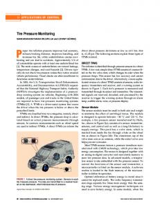
Batch Process Data Preprocessing and Arrangement Prior to developing statistical empirical models, the following features inherent to most batch chemical process data should be addressed and treated. • Time-varying and nonlinear system dynamics: deviations from the mean trajectories of variables can be used to reduce nonlinearity. • Unequal batch lengths: batch data lengths are adjusted and equalized before using multivariate SPM methods. • Noisy, collinear data, including outliers and missing values: data reconciliation is performed. • Differences in magnitudes and variances of measured variables: data are scaled. Batch data are reported in terms of batch runs, variables, and time. Data are arranged into a three-dimensional (3-D) array X( I × J × K ), where I is the number of batches, J is the number of variables, and K is the number of sampling times in a given batch (Fig. 1). Due to the nature of batch processes, every batch may come to completion at a different termination time, resulting in unequal batch data length. The unequal length batch data should be equalized prior to forming a three-way array. Cutting batch data lengths to the length of the variable with the shortest data sequence is not recommended because of the significant information loss
1 2
K
Which Technique to Use?
I 1
J
1
Figure 1. Batch process data representation in three-way array. 42
generated by discarding data. There are several methods for equalizing batch lengths: 1) The indicator variable technique (IVT) is based on selecting a process variable to indicate the progress of the batch instead of the time axis. This variable should be chosen such that it also shows the maturity or percent completion of each batch. Some candidates are percent conversion or percent of a component fed to the processing unit. A measure of the maturity of a batch is provided by the percentage of the final value of the indicator variable attained at the current point in time. Each new observation is taken relative to the progress of this variable. The indicator variable should be smooth, continuous, and monotonic and should span the range of all other process variables within the batch data set. To equalize historical batch data from previous runs where variables might be sampled with respect to time but not represented in terms of an indicator variable, linear interpolation techniques are used to transform batch-time dimension into indicator variable dimension. The IVT technique has been used for several MSPM applications [16]-[18]. 2) Dynamic time warping (DTW) has its origins in speech recognition and is a flexible, deterministic, pattern matching scheme that works with pairs of patterns. It can locally translate, compress, and expand the patterns so that similar features in the patterns are matched. DTW nonlinearly warps two trajectories in such a way that similar events are aligned and a minimum distance between them is obtained. It is assumed that an appropriate scaling was performed prior to implementation of DTW; scaling is an important issue since DTW is a distance-based technique. One can calculate the mean and standard deviation for each variable in each batch trajectory set, take the average of those, and use the average to scale the set of trajectories to a common y-axis scale. The reference batch trajectory set is defined based on process knowledge, or it can be calculated based on an adaptive iteration technique [19]. Basic descriptions of DTW and various algorithms are given in the literature [20], [21], and a recent application for monitoring and diagnosis of a batch polymerization process is reported in [19]. 3) Curve registration is a twofold process of identifying landmarks within a trajectory (or set of trajectories) and then warping the test trajectory to the reference trajectory containing reference landmarks [22]. It provides a means for adjusting the length of data separately for each phase of the batch [23].
Using indicator variables is appealing because of its ease of implementation and insignificant computational burden. But IVT does not account for the locations and the alignment of
IEEE Control Systems Magazine
October 2002
landmarks. Another likely problem with IVT is the lack of an appropriate candidate for a single indicator variable for all phases of a batch. In such cases, further processing is required to apply the technique, such as dividing process phases so that an indicator variable can be identified in each phase. The DTW technique imposes a relatively high computational burden, especially for large data sets. Since DTW is a distance-based technique, it is also susceptible to outliers and noise in the data; it performs better when the outliers are removed and noise is filtered. Curve registration is advantageous when detection and alignment of process landmarks are sought. The challenge of implementing multivariate landmarking is that landmarks may be different (in number and location) for different process variables. Critical issues are the selection of landmarks among the process variables that define the phase phenomena of the process and the number of landmarks to define clearly the progress of the batch. Solutions to these issues were proposed in [24].
Empirical Model Development for SPM Multivariate SPM methods are based on the extension of PCA and PLS techniques to 3-D data (batches × variables × time). Other multiway techniques that are popular in social sciences and chemometrics, such as Tucker and PARAFAC, have also been suggested for the decomposition of three-way data [25], [26]. PCA-based techniques have proven to be more effective for explaining complex interactions among batch process variables [27]. For a given number of components, PCA-based models always fit better than Tucker3 and PARAFAC models, hence explaining relatively greater amounts of variation [28]. Papers comparing the performance of multiway PCA (MPCA) and three-way monitoring methods report differing results. Although MPCA has better performance, according to [27], three-way techniques have outperformed MPCA, according to [28]. Since the focus of this work is mostly on statistical monitoring of multistage chemical processes, all techniques used here are based on variations of PCA. Most techniques suggested for monitoring multistage processes can be extended to product quality monitoring/prediction using PLS.
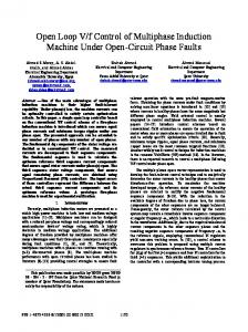
of variation. Operation under various known upsets can also be modeled if sufficient historical data are available to develop automated diagnosis of source causes of abnormal process behavior [33]. Principal components are a new set of coordinates that are orthogonal to each other. The first principal component indicates the direction of largest variation in data; the second principal component indicates the largest variation, not accounted for by the first principal component, in a direction orthogonal to the first principal component. Most of the process information can be described with fewer principal component dimensions than the number of measurements. In this case, for a data set from continuous processes, X has the dimension of ( K × J ), time K versus variable J. PCA involves the orthogonal decomposition of the set of measurements from a process X along the directions that explain the maximum variation in the data. These directions are the eigenvectors p i of XT X or the principal component loadings. The eigenvalues define the corresponding amount of variance explained by each eigenvector. The projection of the measurement observations onto the eigenvectors defines a new point in the measurement space. These points constitute the score matrix, T. T = XP, X = TPT + E or X = t 1 pT1 + t 2 pT2 + L+ t R pTR + E ,
(1)
where X denotes a K × J data matrix with K observations of J variables, P is a K × R matrix whose ith column is the ith eigenvector of XT X , T is a J × R score matrix, and E is a K × J matrix of residuals. Ideally, R is chosen such that there is no significant process information left in E and E contains only random error. A quick approximate method for selecting R is to proceed until the percent of the variation explained by adding additional principal components is small. A more x3 PC1
Principal Component Analysis PCA is a multivariable statistical technique that can extract the essential information from a data set reported as a single block of data such as process measurements. It was originally developed by Pearson [29] and became a standard multivariate statistical technique [30]-[32]. PCA techniques are used to develop a model describing the expected variation under normal operation (NO). A reference data set is chosen to define the NO for a particular process based on the data collected from various periods of plant operation when the performance is good. Then the PCA model is built. This model is used to detect outliers from NO that indicate excessive variation from normal targets or unusual patterns
October 2002
PC2
x2
x1
Figure 2. Principal components of 3-D data set projected on a single plane [33].
IEEE Control Systems Magazine
43
precise method that requires large computational time is cross-validation [34]. For a data set that is well described by two principal components, the data can be displayed in a plane. The data are scattered as an ellipse whose axes are in the direction of principal component loadings in Fig. 2. For a higher number of variables, data will be scattered as an ellipsoid. PCA is sensitive to scaling and outliers. The process data matrix should be mean centered and scaled properly before the analysis. Scaling is usually performed by dividing all the values for a certain variable by the standard deviation for that variable so that the variance in each variable is unity. Scaling is process dependent. If all of the measured variables are in the same units, only mean centering would be enough. Different kinds of scaling can be considered when one wants to give some of the variables or time instances more weight.
Extending PCA to Multiway PCA for Batch Process Monitoring In batch processes, the reference model is developed by considering a number of successful batch runs. Hence, the data matrix X becomes 3-D ( I × J × K ) and will be denoted as X. It can be decomposed using various three-way techniques, including MPCA. MPCA is equivalent to performing ordinary PCA on a large two-dimensional (2-D) matrix constructed by unfolding the three-way array (Fig. 3) [35]. The use of MPCA for batch process monitoring was proposed in [36] and [37] and applied to monitoring a polymerization reactor. MPCA decomposes the three-way X array into a summation of the product of score vectors t r and loading matrices Pr , plus a residual array E that is minimized in a leastsquares sense as R
R
r=1
r=1
X = ∑ t r ⊗ Pr + E or X = ∑ t r pTr + E = X$ + E, (2)
where ⊗ denotes the Kronecker product (X = t ⊗ P is X (i , j , k ) = t (i )P( j , k )) and R denotes the number of principal components retained. The first equation in (2) denotes the 3-D decomposition while the second equation displays the more common 2-D decomposition. Unfolding of the three-way array X can be performed in six possible ways. For instance, X can be unfolded to put each of its vertical slices ( I × J ) side by side to the right, starting with the slice corresponding to the first time interval (Fig. 3). The resulting 2-D matrix X has dimensions ( I × KJ ). This particular unfolding allows one to analyze variability among the batches in X by summarizing information in the data with respect to variables and their time variation. This is the most suitable unfolding technique for statistical process monitoring. A mathematically equivalent unfolding would be to take slices off the side of X and place them down the time axis, thereby also forming an( I × JK ) dimensional matrix. The latter unfolding orders the matrix with the history of each variable kept together, whereas the former orders the matrix with all the measurements taken at the same time kept together. These two unfoldings yield exactly the same result, just in different permutations. Obviously, the choice of unfolding depends on the type of variation one wants to analyze in data. For instance, Wold et al. [38] have recently suggested use of an unfolding in the variable direction resulting in a ( KI × J )-dimensional matrix to predict batch completion times. After mean centering and scaling the unfolded data matrix, PCA is applied. Each of the p, however, is really an unfolded version of the loadings matrix Pr . After p are obtained, Pr can be obtained by reversing the unfolding procedure. Similarly, the three-way array E can be formed by folding the PCA residual matrix E. MPCA explains the variation of measured variables about their average trajectories. Subtracting the average trajectory from each variable (accomplished by mean cen-
τ (1)
τ (2)
τ (K )
v (1) .... v (J )
v (1) .... v (J )
v (1) .... v (J )
t
Scores
b(1)
Batches
b(2)
K X b(l) Time
J
I
pT
Loadings
Variables
Figure 3. Batch data representation and unfolding process. The rows are batches and the columns are the variables, v j , sampled at each time τ k . 44
IEEE Control Systems Magazine
October 2002
tering the columns of the unfolded matrix X) removes most of the nonlinear behavior of the process. The ith elements of the t-score vectors correspond to the ith batch with respect to other batches in the database over the entire history of the batch. The loadings matrices, P, summarize the time variation of the measured variables about their average trajectories. The statistics used for monitoring multivariable batch processes are the statistical distance T or Hotelling’s T 2 (T 2 is also known as the D-statistic in the literature when it is based on batch process data scores and in terms of multipliers used as in (4) and (7) for batch process data) and squared prediction error (SPE). If a new batch is good and consistent with the normal batches, its scores should fall within the normal range and the SPE or Q-statistic (a common SPE measure that is calculated as in (3)) should be small. The Q-statistic andT 2 for end-of-batch SPM for batch i are calculated as KJ
Qi = e i eTi = ∑ E(i , c )2 c= 1
Ti 2 =
tTr S −1 t r I ( I 2 − 1)
where e i is the ith row of E, I is the number of batches in the reference set, t r is a vector of R scores [30], S is the ( R × R) estimated covariance matrix, which is diagonal due to the orthogonality of the t-scores, B denotes the beta distribution, and R is the number of principal components retained in the model [39]. The T 2 statistic in (4) is used for comparing batch scores [40] and follows the beta distribution. If tables for beta distribution are not readily available, this distribution can be approximated using [39] ( R / ( I − R − 1))FR , I − R − 1, α ~ 1 + ( R / ( I − R − 1))FR , I − R − 1, α
J
(
(5)
j=1
October 2002
J
) =∑ ( e 2
(7)
Multivariate Charts for SPM The following multivariate charts are used as tools for visualizing multivariate statistics calculated based on empirical models. Each chart can be constructed to monitor batches or performance of one batch during its evolution. Score biplots or 3-D plots are used to detect any departure from the in-control region defined by the confidence limits calculated from the reference set. The score plots provide a summary of process performance from one batch to the next. The control limits for new independent t-scores under the assumption of normality are given by [42]: ± t n − 1, α / 2 sref (1 + 1 / n)1 / 2 ,
j=1
ijk
where t n − 1, α / 2 is the critical value of the t-student test with n −1 degrees of freedom at significance level α/2, and n and sref are the number of observations and the estimated standard deviation, respectively, of the t-score sample at a given time interval k. The Hotelling’s T 2 plot detects the small shifts and deviations from normal operation defined by the model.T 2 values for each time interval k follow an F-distribution [39] Tk2 ~ FR , I − R ,
where FR , I − R − 1, α is the F-distribution value with R and I − R −1 degrees of freedom at an α significance level. Statistical limits on the Q-statistic and T 2 are computed by assuming that the data have a multivariate normal distribution [30], [41]. Weighting the distance by the inverse of the covariance matrix S accounts for differences in variation and presence of correlation. Variables that have a larger normal variation are weighted less in T 2 . To calculate SPE and T 2 values throughout the batch as soon as the batch is complete, (6) and (7) are implemented for each observation at time interval k [37]. SPE ik = ∑ x ijk − x$ ijk
I ( I − R) . R( I 2 − 1)
We propose a framework for monitoring overall process performance at the end of each batch, providing tools for diagnosing problematic stages.
(3)
~ BR / 2, ( I − R − 1) / 2, α , (4)
BR / 2, ( I − R − 1) / 2, α
Tik2 = t Tikr S −1 t ikr
)2 (6)
where R denotes the number of principal components and I the number of batches in the reference set. The SPE plot shows large variations and deviations from normal operation that are not defined by the model. Calculated SPE values for each time interval k using (6) are well approximated by SPE k ~ gχ 2h , where g is a constant and h is the effective degrees of freedom of the chi-squared (χ 2 ) distribution [43]. Contribution plots are used for fault diagnostics. Both T 2 and SPE charts produce an out-of-control signal when a fault occurs, but they do not provide any information about the cause. Contribution plots forT 2 and SPE indicate which variable(s) are responsible for the deviation from normal opera-
IEEE Control Systems Magazine
45
tion. Calculations of contributions have been given by Miller et al. [44] as
ance plots over time can be used as indicators of the phenomenological/operational changes that occur during the process evolution [1]. This measure can be computed as
K
CT 2 , ijr = ∑ ( x ijk p jkr )2 , k=1
SSE explained, % =
where CT 2 , ijr denotes the batch contribution to the T 2 for batch i, process variable j, and principal component r, and 2 , C SPE, ijk = eijk
where C SPE, ijk is the batch i contribution to the SPE value for process variable j at time k. Variance plots highlight the variabilities of batch profiles. The explained variance is calculated by comparing the real process data with the MPCA model estimates. This can be calculated as a function of batch number, time, or variable number. The value of the explained variance becomes higher if the model accounts for more variability in the data and for the correlation that exists among the variables. VariwT
wTk
t
t
R tk–1
r1
r2
X1 pT1
rk
X2 pT2
drk rk Xk
Xk pTk
pTk
(a)
(b)
Figure 4. Adaptive HPCA technique framework [45]: (a) hierarchical PCA method and (b) adaptive HPCA method.
Stage 1 Stage 2 Phase 1
Phase 2
X2
X1
X1a
X1b
Figure 5. Data arrangement for process stages and phases. 46
E i2 − E$ i2 × 100, ∑ i E i2
where SSE denotes sum of squared errors and E i and E$ i are true and estimated residuals, respectively.
Online Monitoring of Batch Processes Real-time SPM during the progress of the batch can be as simple as monitoring the trajectory of each process variable and comparing it against an ideal reference trajectory. The premise for this approach is that if all variables behave as expected, the product properties will be as desired. A few control loops can be used to regulate some critical process variables. There are several problems with this approach. 1) The univariate control charts do not show disturbances in the correlation structure. 2) Slight changes in many variables may seem too small for each variable, but their collective effect may be significant. 3) Variations in impurity levels or other initial conditions may affect the variable trajectories, but these deviations from the reference trajectories may not cause significant product quality degradation. 4) The duration of each batch may be different, causing difficulties in comparing the trajectories of the current batch to reference trajectories. Multivariate SPM tools provide solutions to these problems. However, the MSPM tools based on MPCA or other three-way techniques necessitate the knowledge of the whole time trajectory of each variable. The remedies proposed for this constraint fall into three groups: 1) use the MSPM tools with variable trajectories that are combinations of real data (up to the present time in the batch) and estimates of the future portion of the trajectories to the end of the batch; 2) use hierarchical PCA that relies only on trajectory information from the beginning of the batch to the current time; 3) use estimators for predicting the final product quality and base batch monitoring on this estimate. To implement the first method to remedy lack of measured data for the future portion of the variable trajectories, several techniques have been suggested to fill in missing values in X new . The conventional approach is to make several assumptions based on the process knowledge about the future values [37]. One approach assumes that the future values of disturbances remain constant at their current values over the remaining batch period. A second approach assumes that the future observations are in perfect accordance with their mean trajectories. A third approach treats unknown future observations as missing values from the batch in the MPCA model. Hence, principal
IEEE Control Systems Magazine
October 2002
components of the reference batches can be used for prediction. All three assumptions introduce arbitrariness in the trajectory estimates. Recently, a new approach based on a hierarchical PCA (HPCA) technique [11] has been suggested by Rannar et al. [45] and illustrated with applications in polymer production and penicillin fermentation [46]. HPCA provides a framework for dividing the data block X into K blocks of 2-D ( I × J ) data (Fig. 4(a)) and looking at one time slice at a time (Fig. 4(b)). For online monitoring, building conventional MPCA models at points corresponding to certain percent completions of a batch has also been proposed [28]. In adaptive HPCA (AHPCA), gradual progress of the process can be modeled for each time instance, also incorporating previous time slices. Too many separate models are needed with conventional MPCA models, built at certain time intervals as data become available, increasing the computational burden.
Multistage Process Monitoring and Data Analysis
Case Study: Pharmaceutical Granules Production Monitoring Process Description and Data Pretreatment Pharmaceutical granules are among the most commonly used solid dosage forms for the production of oral drug forms such as tablets, sachet granules, and capsules. Wet granulation followed by drying is widely used in the pharmaceutical industry. Wet granulation and drying are consecutive processing stages that have a significant effect on the
12
10
Fb Pw Phase Switch
8
6
Moisture [%]
Moisture [%]
Many chemical processes consist of several distinct pro4 cessing units. Data from various processing “stages” carried Phase 1 Phase 2 in processing units and “phases” for operational or 2 phenomenological regions in single units provide information about the progress of the batch. As the number of units and phases increases, the complexity of the monitoring 0 0 20 40 60 80 100 120 140 problem also increases. The aforementioned techniques Observation Number and multivariate charts are used for monitoring these types of processes with some modifications in both data pretreat- Figure 6. Phase structure of the first stage. F : binder addition b ment and monitoring algorithms. rate; Pw : agitator power consumption. Pharmaceutical granule production by wet granulation following a 12 12 fluidized-bed drying operation was 10 10 chosen as a test case for this study. 8 8 Process variables were broken up into 6 6 blocks that correspond to certain processing stages. The choice of blocks 4 4 depends on engineering judgment 2 2 and the objectives of the study. In this 0 0 study, blocks are related to particular 0 1 2 3 4 5 6 7 8 0 20 40 60 80 100 120 140 160 processing units. Furthermore, due to Time [min.] Observation Number (a) (b) the different operating regimes occurring in each unit, it is convenient to 0.25 0.22 0.20 split the data from a stage into phases 0.2 0.18 (Fig. 5). This way, the predictive and 0.16 diagnostic capabilities of the multi0.15 0.14 0.12 variate statistical models can be im0.1 0.10 proved and provide a more accurate 0.08 inference about the whole process. 0.05 0.06 0.04 These models can be used to elimi0 0.02 0 0.5 1.5 nate major disturbances in future 1 2 0 10 20 30 40 50 60 70 Time [h] Observation Number batches and therefore help in adjust(c) (d) ing control limits for more consistent production that is crucial for pharma- Figure 7. Equalized process variable trajectories of both stages using indicator variable ceutical production processes [5]. technique. (a), (b) Before equalization. (c), (d) After equalization.
October 2002
IEEE Control Systems Magazine
47
Sum of Squares Explained [%]
50
40
Phase 1
30
Phase 2
PC1 – OM PC2 – OM PC1 – LM1 PC2 – LM1 PC1 – LM2 PC2 – LM2
20
10
0 0
20
40
60 80 100 120 Observation Number
140
160
Figure 8. Comparison of local and overall models and performances on explained variance.
25 Overall Model (CM) Local Model (LM) 95% Limit (OM) 99% Limit (OM) 95% Limit (LM) 99% Limit (LM)
20
SPE
15
10
5
0 0
20
40
60 80 100 120 Observation Number (a)
140
160
25 Overall Model Local Model 95% Limit 99% Limit
20
T2
15
final product quality, as well as on the intermediate product (wet granules) quality. In this study, possible changes in granulate characteristics during the waiting period for the next processing stage are neglected. Based on the existing pharmaceutical literature, a generic process model was developed and data were produced by means of simulation studies. Normal operating condition data were generated to develop multivariate statistical models of the process [47]. Stage 1 is the wet granulation of the fine powder mix of active ingredient(s) and other pharmaceutical excipients. The objective of the granulation is to increase the particle size by agglomerating this fine powder by adding a binder solution under continuous mixing. Particle size increase promotes higher bioavailability of the drug. At this stage, the amount of binder used and its addition rate are effective on the particle size increase. The amount of binder solution and its addition rate are predefined based on experimental design studies. We have assumed a fixed total amount of binder solution in the simulation studies. Binder addition rate, impeller speed, and power consumption are taken as measured process variables at this stage. Stage 1 is operated in two phases: phase 1, dry mixing for a fixed time interval, and phase 2, binder addition while mixing (Fig. 6). Since there are some small fluctuations in binder flow rate at each batch, the final time of the second phase is variable, producing unequal batch lengths for stage 1. These differences should be eliminated prior to multivariate statistical modeling. To equalize data lengths in phase 2, we have used percent binder solution added into the granulator as an indicator variable and sampled each variable at every 1% increase in this variable, resulting in 100 observations for each batch in this phase. These equalized data are appended to the fixed data of the first phase, resulting in a total of 160 observations for stage 1 (Fig. 7(a) and (b)). Stage 2 is the drying stage where a fluid bed dryer is used. The wet granulates are dried using hot airflow to decrease their moisture content. The increase in product temperature is measured as an indicator of drying. Airflow rate, inflow air temperature, drying rate, and product moisture are also measured. Product temperature is found to be appropriate as an indicator variable for this stage, and measurements on each variable are interpolated on every 0.5 °C increase in product temperature, resulting in 63 observations (Fig. 7(c) and (d)).
10
5
0 0
20
40
60 80 100 120 Observation Number (b)
140
160
Figure 9. Effects of overall and local modeling on process performance monitoring.
48
Stage
Reference Data Set
Data Array Size
1
X1 (Overall)
78 × 3 × 160
Phase 1
X1a
78 × 2 × 60
Phase 2
X1b
78 × 3 × 100
X2
78 × 4 × 63
2
IEEE Control Systems Magazine
October 2002
Monitoring Individual Stages Monitoring individual stages can be considered as monitoring a single batch processing unit. This can be done either at the end of the batch or during the batch. For both stages, 80 batches representing NO were simulated by introducing small perturbations in initial conditions and using PRBS input sequences. The resulting data are preprocessed by equalizing lengths, constructing the three-way data arrays, and unfolding and scaling data appropriately (zero mean, unit variance). After the initial modeling effort, two batches are removed from the reference set, since they are outside the main data cluster (representing NO) and the control limits and are treated as outliers. The reference data after preprocessing for multivariate mod150 eling are given in Table 1.
X ijk = [X ij 1k 1
40 30
T2
SPE
50
0
20 10
0
0
50 100 150 Observation Number
0.5
0
0
50 100 150 Observation Number
1
CT 2
CSPE
1
Fb
Nr
0.5
0
Pw
Fb
Nr
Pw
(a) 10
200
T2
SPE
150 100
5
50 0 0
0
20 40 60 Observation Number
CT 2
0.5
0
0
20 40 60 Observation Number
1
1
CSPE
While monitoring individual stages, structure of the data should be taken into consideration prior to statistical modeling. When data cover different phases of the process due to operational or phenomenological changes, this structure should be carefully analyzed to improve the precision of statistical monitoring techniques. This can be done by developing local models based on data from each phase instead of the whole data for each stage. Using local models with precise division of data based on landmarks of a phase has advantages. It allows one to unveil the correlation structure that exists in the data, specific to each phase, that might not be possible by using the overall data. The advantage of using indicator variables is that process data can be aligned based on similar events to provide consistency in analysis and modeling. However, generating more precise models depends on how precisely the phases and their landmarks are identified so that the data can be separated into blocks. The indicator variable technique provides phase completion information that can be used for data division instead of depending only on the process experience. At the first stage of the granule production process are two operational phases. The first phase contains dry mixing for a fixed time, and the second phase involves wet massing. Since the total amount of binder to be added is fixed, the exact completion of the second phase is reached when all of the binder solution is consumed. The data from the first phase are collected based on the fixed operation time, resulting in the X ij 1k 1 unfolded matrix. The data arrangement in the second phase is based on a
X ij 2k 2],
where j = j1 + j2 and k = k1 + k2. Two local models for phase 1 and phase 2, and one overall model, are developed using the MPCA technique and
100
End-of-Batch Monitoring of a Processing Stage
October 2002
fixed indicator variable (percent binder addition), resulting in X ij 2k 2 . The index pairs j1, k1and j2, k2denote variables and observation numbers at each phase, respectively. The overall performance can also be investigated by appending these matrices to form an augmented matrix as
Fa
Ta
mH2O
dr
0.5
0 (b)
Fa
Ta
mH2O
dr
Figure 10. AHPCA-based online monitoring of process stages under faulty operation. (a) Stage 1. Fb : binder addition rate; N r : impeller speed; Pw : power consumption. (b) Stage 2. Fa : inflow air rate; Ta : inflow air temperature; mH 2 O : product moisture (%); dr : drying rate.
IEEE Control Systems Magazine
49
wT
wT
tc
tc C
C
t1
t1a
t2
X1
X 1a
X2
X2
X 1b
pT1b
pT1a
pT2
pT1
t2
t1b
(a)
pT2 (b)
Figure 11. Higher-level modeling schemes for stage-wise fault detection.
1
CT 2
New Batch Reference
0.5
0
1
2
PC (a)
3
4
1
CT 2
New Batch Reference
0.5
0
1
2
PC (b)
3
4
Figure 12. Fault detection in stages using higher models. 50
compared. Variance plots can be useful for comparing different models and investigating the changing variance structure. The explained variance is higher (45.67% more) for the local model of phase 1 than the overall model, whereas explained variances are much closer but still higher (4.22% more) for the local model of phase 2 (Fig. 8). This is expected, since the same event occurs in the second phase (Fig. 6). Local models explain more information (17.98% more for the whole process) based on computations of sum of squared errors and data lengths in each phase. A new batch where a small drift in impeller speed was introduced at 0.5 min (tenth observation in phase 1 of stage 1) was monitored after its completion. Note that the fault starts early in the first phase. Both SPE andT 2 plots for local and overall models in Fig. 9 indicated that there is a deviation from the NO. Since overall model performance is not high in the first phase, the early departure is caught later with monitoring based on the overall model than with monitoring based on the local model (Fig. 10(b)), and many false alarms are observed in the SPE plot (Fig. 10(a)). The advantages of using the local model for phase 1 are: 1) The false alarms observed with the overall model are discarded for phase 1 in the SPE plot. 2) Departures from the NO are detected earlier (by three observations) than with the overall model, and more consecutive out-of-control points (run length of 12 observations) are observed in the T 2 plot with the local model for phase 1 than with the overall model (six observations). The case illustrates that local models provide the capability to detect earlier small trends and departures from NO that will be propagated to the next phase and eventually cause significant deviation, thus allowing process operators to improve their operations.
IEEE Control Systems Magazine
October 2002
Online Monitoring of the Processing Stages Online monitoring was performed in each processing stage based on AHPCA. The AHPCA algorithm looks at only one time slice at a time, resulting in separate score vectors for each time slice. The previous score vector summarizing recent prior history and the score vector from the current time slice are used to form a two-column matrix that is used to develop the adaptive model (Fig. 4(b)). Since t a ( k − 1) contains the weighted information from the recent history, AHPCA works similar to the exponentially weighted moving-average technique, and phase changes can be monitored effectively. However, for this multistage process, AHPCA is limited to individual stages due to interstage discontinuity. To overcome this problem, different AHPCA models are developed for each stage. Different weightings can also be applied to better account for changing phase structure. To illustrate online monitoring, a case is generated (Fig. 10) where a small drift in impeller speed is introduced (dashed line) in the first stage and a step increase (dashed line) in inflow air rate in the second stage. Each AHPCA model successfully detected and diagnosed the problem online in each stage for the overall process.
Fault Detection and Diagnosis for Stages When a historical batch data set is available for a multistage process, performing postmortem SPM may provide useful insight about past production history, allowing improvements for the upcoming batches at a particular stage or stages of the batch process. This can be done by developing models for each stage and investigating the process performance through multivariate charts. Higher-level models (super models) may help to look at the whole process and its stages/phases with a bird’s-eye view. When a problem is detected in a particular stage, a detailed investigation is started regarding that stage. Super-level models are developed from stage models and contain information about the expected normal behavior for the overall process. The statistics generated by the super-level model can be used to identify the stages, or even phases in stages, where a process upset exists. Using a super-level model decreases the number of MV charts to be analyzed, hence decreasing the time required for thorough analysis of the past history. The first step is to develop separate models (PCA or PLS based) for each process stage and gather the scores matrices into what can be called a super-level matrix (or consensus matrix), since the scores contain the summary information about the past behavior of the process (or its stages/phases). If there are different phases in a process stage, these phases can also be included in the analysis by developing phase-based models that increase our capability to identify events localized in phases. This is comparable to using a magnifying glass on data at different levels (Fig. 11). The degree of magnification can be adjusted if
October 2002
needed by using phase-based models to form the consensus matrix (Fig. 11(b)). This allows one to detect localized faults in phases of any process stage. For simplicity, a super-level model for the whole process was developed from two data blocks of the process stages (Fig. 11(a)), and the contributions of principal components to T 2 of the consensus matrix are calculated to account for deviations from NO localized in stages. Two principal components from each stage model are used to form a consensus matrix. T 2 contributions of principal components of each batch in the reference set were also calculated for comparison purposes. These contributions are used to identify stages where faults may exist. Fig. 12(a) shows a case where a fault is detected at the first stage due to an inflated first principal component contribution that contains information about the first stage. A similar situation is observed in Fig. 12(b) for the second stage principal components, suggesting a localized fault. Once a fault is detected using this super-level model, one can always proceed with standard end-of-batch SPM models and charts. The procedure can be automated to locate faults in stages, and detailed MSPM charts can be produced when needed.
Conclusions In this study, an MSPM framework for multistage, multiphase processes was proposed where pharmaceutical granules production was used as a case study. Local models were proven to be advantageous when different phases exist in process stages and when precise phase separation is crucial. Online SPM was performed through different AHPCA models, since stage-wise continuity did not exist in variable readings. Overall process monitoring was performed using super-level models based on a consensus matrix to identify localized faults in process stages/phases. This identification provides a means of decreasing the time required for the assessment of historical batch process data as well as newly completed batches. The whole procedure can also be integrated with a knowledge-based system to include explanations about the diagnostics.
References [1] K.A. Kosanovich, K.S. Dahl, and M.J. Piovoso, “Improved process understanding using multiway principal component analysis,” Ind. Eng. Chem. Res., vol. 35, pp. 138-146, 1996. [2] C. Ündey, E. Tatara, B.A. Williams, G. Birol, and A. Çinar, “A hybrid supervisory knowledge-based system for monitoring penicillin fermentation,” in Proc. Amer. Contr. Conf., Chicago, IL, 2000, pp. 3944-3948. [3] B.M. Wise, N.B. Gallagher, S.W. Butler, D. White, and G.G. Barna, “A comparison of principal components analysis, multi-way principal components analysis, tri-linear decomposition and parallel factor analysis for fault detection in a semiconductor etch process,” J. Chemomet., vol. 13, pp. 379-396, 1999. [4] J.A. Westerhuis and P.M.J. Coenegracht, “Multivariate modelling of the pharmaceutical two-step process of wet granulation and tableting with multiblock partial least squares,” J. Chemomet., vol. 11, pp. 379-392, 1997. [5] C. Ündey, I. Boz, E. Oztemel, and A. Çinar, “Statistical monitoring of multistage batch processes,” in Proc. AIChE Ann. Meet., Dallas, TX, 1999. [6] B.M. Wise and N.B. Gallagher, “The process chemometrics approach to process monitoring and fault detection,” J. Process Contr., vol. 6, no. 6, pp. 329-348, 1996.
IEEE Control Systems Magazine
51
[7] J.V. Kresta, J.F. MacGregor, and T.E. Marlin, “Multivariate statistical monitoring of process operating performance,” Canad. J. Chem. Eng., vol. 69, pp. 35-47, 1991. [8] L.E. Wangen and B.R. Kowalski, “A multiblock partial least squares algorithm for investigating complex chemical systems,” J. Chemomet., vol. 3, pp. 3-20, 1988. [9] J.F. MacGregor, C. Jaeckle, C. Kiparissides, and M. Koutoudi, “Process monitoring and diagnosis by multiblock PLS methods,” AIChE J., vol. 40, no. 5, pp. 826-838, 1994. [10] T. Kourti, P. Nomikos, and J.F. MacGregor, “Analysis, monitoring and fault diagnosis of batch processes using multiblock and multiway PLS,” J. Process Contr., vol. 5, no. 4, pp. 277-284, 1995. [11] S. Wold, N. Kettaneh-Wold, and K. Tjessem, “Hierarchical multiblock PLS and PC models, for easier model interpretation, and as an alternative to variable selection,” J. Chemomet., vol. 10, pp. 463-482, 1996. [12] J.A. Westerhuis, T. Kourti, and J.F. MacGregor, “Analysis of multiblock and hierarchical PCA and PLS models,” J. Chemomet., vol. 12, pp. 301-321, 1998. [13] R. Boque and A.K. Smilde, “Monitoring and diagnosing batch processes with multiway regression models,” AIChE J., vol. 45, pp. 1504-1520, 1999. [14] A.K. Smilde, J.A. Westerhuis, and R. Boque, “Multiway multiblock component and covariates regression models,” J. Chemomet., vol. 14, pp. 301-331, 2000. [15] D. Dong and T.J. McAvoy, “Batch tracking via nonlinear principal component analysis,” AIChE J., vol. 42, pp. 2199-2208, 1996. [16] T. Kourti, J. Lee, and J.F. MacGregor, “Experiences with industrial applications of projection methods for multivariate statistical process control,” Comp. Chem. Eng., vol. 20, Suppl. A, p. 745, 1996. [17] S.G. Rothwell, E.B. Martin, and A.J. Morris, “Comparison of methods for handling unequal length batches,” in Proc. IFAC DYCOPS5, Corfu, Greece, 1998, pp. 66-71. [18] D. Neogi and C. Schlags, “Multivariate statistical analysis of an emulsion batch process,” Ind. Eng. Chem. Res., vol. 37, no. 10, pp. 3971-3979, 1998. [19] A. Kassidas, J.F. MacGregor, and P.A. Taylor, “Synchronization of batch trajectories using dynamic time warping,” AIChE J., vol. 44, no. 4, pp. 864-875, 1998. [20] H. Sakoe and S. Chiba, “Dynamic programming algorithm optimization for spoken word recognition,” IEEE Trans. Acoust., Speech, Signal Process., vol. 26, pp. 43-49, 1978. [21] L.R. Rabiner, A.E. Rosenberg, and S.E. Levinson, “Consideration in dynamic time warping algorithms for discrete word recognition,” IEEE Trans. Acoust., Speech, Signal Process., vol. 26, p. 575, 1978. [22] J.O. Ramsay and B.W. Silverman, Functional Data Analysis. New York: Springer-Verlag, 1997. [23] B.A. Williams and A. Çinar, “An on-line monitoring and curve registration system for multivariable batch processes,” presented at AIChE Ann. Meet., Los Angeles, CA, 2000. [24] B. Williams, C. Ündey, and A. Çinar, “Detection of process landmarks using registration for on-line monitoring,” in Proc. IFAC DYCOPS6, Cheju Island, Korea, 2001, pp. 257-263. [25] A.K. Smilde, “Three-way analysis. Problems and prospects,” Chemomet. Intell. Lab. Syst., vol. 15, pp. 143-157, 1992. [26] R. Bro, “PARAFAC. Tutorial and applications,” Chemomet. Intell. Lab. Syst., vol. 38, pp. 149-171, 1997. [27] J.A. Westerhuis, T. Kourti, and J.F. MacGregor, “Comparing alternative approaches for multivariate statistical analysis of batch process data,” J. Chemomet., vol.13, pp. 397-413, 1999. [28] D.J. Louwerse and A.K. Smilde, “Multivariate statistical process control of batch processes based on three-way models,” Chem. Eng. Sci., vol. 55, pp. 1225-1235, 2000. [29] K. Pearson, “On lines and planes of closest fit to systems of points in space,” Philos. Mag., vol. 2, pp. 559, 1901. [30] J.E. Jackson, A Users Guide to Principal Components. New York: Wiley, 1991. [31] R.A. Johnson and D.W. Wichern, Applied Multivariate Statistical Analysis, 4th ed. Englewood Cliffs, NJ: Prentice-Hall, 1998. [32] I.T. Jolliffe, Principal Component Analysis. New York: Springer-Verlag, 1986.
52
[33] A. Raich and A. Çinar, “Statistical process monitoring and disturbance diagnosis in multivariable continuous processes,” AIChE J., vol. 42, no. 4, pp. 995-1009, 1996. [34] S. Wold, “Cross-validatory estimation of the number of components in factor and principal components analysis,” Technomet., vol. 20, no. 4, pp. 397-405, 1978. [35] S. Wold, P. Geladi, K. Esbensen, and J. Ohman, “Multi-way principal component and PLS analysis,” J. Chemomet., vol. 1, pp. 41-56, 1987. [36] P. Nomikos and J.F. MacGregor, “Monitoring batch processes using multiway principal component analysis,” AIChE J., vol. 40, no. 8, pp. 1361-1375, 1994. [37] P. Nomikos and J.F. MacGregor, “Multivariate SPC charts for monitoring batch processes,” Technomet., vol. 37, pp. 41-59, 1995. [38] S. Wold, N. Kettaneh, H. Friden, and A. Holmberg, “Modelling and diagnostics of batch processes and analogous kinetic experiments,” Chemomet. Intell. Lab. Syst., vol. 44, pp. 331-340, 1998. [39] N.D. Tracy, J.C. Young, and R.L. Mason, “Multivariate control charts for individual observations,” J. Quality Contr., vol. 24, no. 2, pp. 88-95, 1992. [40] H. Hotelling, “Analysis of a complex of statistical variables into principal components,” J. Educ. Psychol., vol. 24, pp. 417, 1933. [41] J.E. Jackson, “Principal components and factor analysis: Part I—Principal components,” J. Quality Technol., vol. 12, no. 4, pp. 201-213, 1980. [42] G.J. Hahn and W.Q. Meeker, Statistical Intervals. A Guide to Practitioners. New York: Wiley, 1991. [43] G.E.P. Box, “Some theorems on quadratic forms applied in the study of analysis of variance problems: Effect of inequality of variance in one-way classification,” Ann. Math. Statist., vol. 25, pp. 290-302, 1954. [44] P. Miller, R.E. Swanson, and C.F. Heckler, “Contribution plots: The missing link in multivariate quality control,” Appl. Math. Comp. Sci., vol. 8, no. 4, pp. 775-792, 1998. [45] S. Rannar, J.F. MacGregor, and S. Wold, “Adaptive batch monitoring using hierarchical PCA,” Chemometr. Intell. Lab. Syst., vol. 41, pp. 73-81, 1998. [46] C. Ündey, E. Tatara, B.A. Williams, G. Birol, and A. Çinar, “On-line real-time monitoring of penicillin fermentation,” in Proc. Int. Symp. Advanced Contr. Chem. Processes (ADCHEM 2000), Pisa, Italy, 2000, pp. 243-248. [47] C. Ündey, “Development of an intelligent hybrid monitoring and control system for batch processes,” Ph.D. dissertation, Univ. Istanbul, Dept. Chem. Eng., Avcilar- Istanbul, Turkey, 1999.
Cenk Ündey obtained his B.S., M.S., and Ph.D. degrees in chemical engineering from the University of Istanbul, Turkey, in 1992, 1995, and 1999, respectively. He conducted research for the last two years of his Ph.D. studies in the Department of Chemical and Environmental Engineering at Illinois Institute of Technology, where he is currently a senior research associate. His main research interests are statistical process monitoring, batch process modeling and monitoring, and development of integrated intelligent systems for supervising process operations. Ali Çinar received a B.S. degree in chemical engineering from Robert College, Turkey, in 1970 and M.Eng. and Ph.D. degrees from Texas A&M University in 1973 and 1976, respectively. He is a professor of chemical engineering, Dean of the Graduate College, and Associate Vice President for Research at Illinois Institute of Technology. His teaching and research interests are continuous and batch process modeling and control, statistical process monitoring and fault diagnosis, and use of knowledge-based systems for real-time process supervision and control.
IEEE Control Systems Magazine
October 2002