Sensorless Multiphase Induction Motor Drive Based on a Speed Observer Operating with Third-Order Field Harmonics M. Mengoni, L. Zarri, A. Tani, G. Serra, D. Casadei Department of Electrical Engineering University of Bologna Bologna, Italy
[email protected] It is worth noting that the performance of vector controlled motor drives can be remarkably affected by the accuracy of the speed or position measurements. Since rotational transducers and their associated digital or analog circuits give extra costs and are often complex or fragile, the interest by industry in solutions without rotational sensors — the so-called sensorless IM drives - has never diminished. Given that high-performance controllers are readily available when speed and flux are known, it seems reasonable to estimate the speed and flux, in the spirit of observer and control theories, to replace the actual speed and flux in the control scheme by its estimation.
Abstract— This paper presents an electric drive consisting of a multiphase induction motor fed by multiphase inverter. The control system is similar to that of a traditional field-oriented control for three-phase motors, but the machine state is determined by a novel sensorless observer. Since multiphase motors with M phases (M is supposed odd) have the capability of controlling the spatial harmonics of the magnetic field up to the (M-2)th order, the proposed observer excites the thirdorder spatial harmonic of the magnetic field to estimate the rotor speed. Experimental results are provided to show the feasibility of the electric drive.
I.
INTRODUCTION
So far, very little research has been done on the sensorless control of multiphase electric drives. Among the cited papers, only few investigated the sensorless control of multiphase drives, and the methods developed for the control of the machines are reasoned adaptations of the three phase counterparts [13], [14], [17]- [19].
Nowadays, there is an increasing interest towards multiphase motor drives, especially for medium and high power applications such as naval and railway propulsion systems. The use of multi-phase drives has been recognized as a viable approach to obtain high power ratings without increasing the stator current per phase, making it possible to use standard power switches based on a single device.
In this context, the present paper faces the problem of the sensorless speed estimation of multiphase induction motors with an odd number of phases from a different point of view and explores a new way to exploit the inherent degrees of freedom of multiphase motors, based on the use of thirdorder spatial harmonic of the magnetic field. The performance of the control scheme is verified by experimental tests carried out on a prototype of seven-phase induction motor drive.
Furthermore, multiphase motor drives have several advantages over traditional three-phase motor drives, such as reducing the amplitude and increasing the frequency of torque pulsations, and improving the reliability and fault tolerance [1]-[2]. Several control schemes, based on field oriented control, have been presented for multiphase drives. These control strategies have been applied to symmetrical, unsymmetrical and special multiphase machines as well as multi-motor drives [3]-[10].
II.
However, multiphase drives offer some degrees of freedom that can be exploited to obtain special behaviors. For example, it is possible to increase the torque density by adding a third-order spatial harmonic in the magnetic field. This feature has been exploited in permanent magnet synchronous motors [11]-[14] and in induction motor drives [15]-[19].
978-1-4577-0541-0/11/$26.00 ©2011 IEEE
MACHINE EQUATIONS
Let us consider an electrical induction machine having M star connected stator phase windings, symmetrically distributed within the stator slots, where M is an odd number greater than three. The behavior of the machine can be described with an opportune mathematical model, which takes into account the spatial distribution of the magnetic field in the air gap up to the third harmonic. As known, it is
68
not possible to analyze a multi-phase motor drive using the space vector representation in a single d-q plane. On the contrary, it is necessary to adopt the space vector representation in multiple d-q planes (multiple space vectors) [20]-[21].
generate the third-order spatial harmonic. The set of equations (1)-(4) is practically equal to that of a three-phase motor and therefore it is possible to adopt a field-oriented control scheme that it is based on the same principles of three-phase drives.
For our purposes it is sufficient to focus on the planes d1q1 and d3-q3, which are related to the fundamental and the third harmonic component of the magnetic field. The equations of the machine in these planes, synchronous with the corresponding rotor flux vectors, are as follows: vS1 = RS iS1 + j ω1 ϕS1 +
d ϕS 1 dt
0 = RR1 iR1 + j (ω1 − ωm ) ϕR1 +
d ϕR1 dt
(1)
III. (2)
ϕS 1 = LS 1 iS1 + M 1 iR1
(3)
ϕR1 = M 1 iS1 + LR1 i R1
(4)
vS 3 = RS iS 3 + j ω3 ϕS 3 +
d ϕS 3 dt
0 = RR 3 iR 3 + j (ω3 − 3 ωm ) ϕR 3 +
d ϕR 3 dt
The set of equations (5)-(8), which describes the behavior of the third-order field harmonic, is similar to that of a threephase motor, except for the factor 3 in front of the rotor speed. However, whereas the fundamental component of the field has to be driven by the control system in order to satisfy the torque demand, the use of the third harmonic component may be considered as a degree of freedom.
A. Basic Principle Assuming that reference frame d3-q3 is aligned with the rotor flux ϕR 3 , projecting (6) on the q-axis, and expressing the rotor currents in terms of the stator currents, leads to the following equation:
(5)
τ R 3 (ω3 − 3ωm )ϕ R 3 = M 3iS 3q
(6)
ϕS 3 = LS 3 iS 3 + M 3 iR 3
(7)
ϕR 3 = M 3 iS 3 + LR 3 iR 3
(8)
M iS 3 q ⎞ 1⎛ ⎟ ωm = ⎜⎜ ω3 − 3 τ R 3 ϕ R 3 ⎟⎠ 3⎝
(11)
Equation (11) shows that the rotor speed can be estimated by calculating the angular speed ω3 of the third harmonic, but unfortunately it depends also on iS3q, ϕR3 and the parameters M3, τR3. If the current iS3q is not null, the motor may incur troublesome torque disturbances due to the interaction between the third-order spatial harmonics of the magnetic field. One comes to this conclusion by examining (9), rewritten in terms of current components as follows:
If the motor is excited only by voltage vectors lying in planes d1-q1 and d3-q3, the expression of the torque is as follows: M p (M 1 iS 1 ⋅ j iR1 + 3 M 3 iS 3 ⋅ j iR 3 ) 2
(10)
The expression of the motor speed can be found by solving (10) for ωm, as follows:
where iSk and iRk (k=1, 3) are the multiple space vectors of the stator and rotor currents, ϕSk and ϕRk (k=1, 3) are the multiple space vectors of the stator and rotor fluxes, ωk is the angular speed of the kth rotor flux vector, ωm is the rotor angular speed in electric radians, and LSk, LRk and Mk (k=1, 3) are coefficients that can be interpreted as self and mutual inductances. The stator resistance RS is assumed to be the same for the planes d1-q1 and d3-q3, whereas two different resistances RR1 and RR3 are considered for the rotor windings.
T=
SPEED OBSERVER
The two sets of equations (1)-(4) and (5)-(8) are independent of each other, except for the rotor speed. This observation suggests that, if a small third-order field harmonic is present, (5)-(8) may be used to estimate the rotor speed.
T=
M p (M 1 iS 1d iS 1q + 3 M 3iS 3 d iS 3q ) 2
(12)
Furthermore, the rotor parameters related to the plane d3q3 are usually known with little accuracy.
(9)
All these problems can be overcome if the control system produces only the current components iS3d, whereas iS3q is set to zero. The current iS3d is necessary to generate the thirdorder field harmonic, and should be as small as possible, provided that the harmonic is detectable.
where p is the number of pairs of poles and the operator "⋅" is the dot product. It is worth noting that the current space vectors iS 1 and iR1 are responsible for the fundamental spatial component of
Under these assumptions, (11) shows that ω3 is equal to 3ωm and therefore it is possible to derive the rotor speed
the magnetic field in the air gap, whereas iS 3 and iR 3 69
directly from the knowledge of ω3.
A closed-loop estimator is based on the principle that feeding back the difference between the measured output of the observed system and the estimated output, and continuously correcting the model by the error signal, the error should be minimized. In the case of a flux estimator, the motor flux cannot be directly measured, but the idea of realizing a closed-loop system is still applicable if the difference between a signal representing the steady-state value of the reference flux and the signal of the estimated flux vector is used as feedback signal.
It is worth noting that the third spatial harmonic of the magnetic field and the fundamental component are not synchronized, and this leads not only to distortions in the waveform of the currents, but also to beatings in the current amplitude. However, the torque produced by the drive is constant, since the third-order field harmonics do not provide any torque contribution.
B. Estimation of the Flux Vector ϕR 3
Hence, (15) is replaced by the following equation:
Equation (11) is written with respect to a reference frame with the d-axis aligned with the rotor flux vector ϕR 3 . Consequently, the control system has to calculate the phase angle of this vector to identify the orientation of the reference frame d3-q3.
(
The estimation of ϕR 3 can be performed by using one of the innumerable methods designed for three-phase induction motors and adapted to multiphase motors [22]-[23]. Each of them has its own advantages and disadvantages. However, it is interesting to note that the angular frequency ω3, in this specific application, is three times the motor speed. Since state observers for induction motors tend to perform better at higher frequencies, the estimation accuracy of the observer for ϕR 3 is expected to be higher than that of the counterparts designed for the fundamental spatial harmonic of the magnetic field.
ϕRS3,ref = M 3 I S 3d ,ref e jθ3
C. Magnetizing Current for the 3rd Spatial Harmonic of the Magnetic Field The current iS3d leads to an increase of the motor Joule losses. Furthermore, by adding the third-order spatial harmonic, the magnetic field may overcome the rated peak value assumed by the designer of the motor. To avoid further iron saturation, the choices of set-points IS1d,ref and IS3d,ref should satisfy the following constraint: 1 I S 1d ,ref + I S 3d ,ref ≤ I S 1d ,rated . 3
According to this method, the rotor flux ϕR 3 can be estimated as follows:
(
LR 3 S ϕS 3 − σ 3 LS 3iSS M3
)
(17)
where IS3d,ref is the set-point of the flux-producing current component. This observer is usually appreciated for its simplicity, and for the low requirements of implementation.
The most simple flux observer is the one based on the integration of the back electromotive force. This flux observer operates in the stator reference frame. Hereafter the superscript “S” will be used to identify quantities expressed in this reference frame.
ϕRS3 =
)
d ϕSS3 (16) = vSS3 − RS iSS3 + Gr ϕRS 3,ref − ϕRS 3 . dt where quantity Gr is the gain of the flux observer. Let us s denote with θ3 the phase angles of ϕR3 in the stator reference frame. Then, the reference flux vector can be calculated as
(18)
The quantity IS1d,rated in (18) is the rated magnetizing current of the motor operating without third spatial harmonic, i.e., the magnetizing current that produces the nominal sinusoidal spatial distribution of the air-gap magnetic field.
(13)
where σ3 is the leakage coefficient defined as
(14)
Consequently, to avoid an excessive reduction of the fundamental flux level, IS3d,ref should be as small as possible.
The stator flux could be determined by integrating the stator voltage:
However, IS3d,ref cannot be chosen too small, because it is related to the magnitude of the rotor flux ϕR 3 . In steady-state operating conditions, the magnitude of ϕR 3 in a rotororiented reference frame is equal to ϕR3d . On its turn, ϕR3d is proportional to iS3d, as follows:
σ3 = 1 −
M 32 . LS 3 LR 3
d ϕSS3 = v SS3 − RS iSS3 . dt
(15)
It is evident from (14) that the estimation of the stator flux vector can be affected by stator resistance mismatch, sensor offsets and inverter non-linearities such as inverter dead-times and voltage drops on the conducting switches. In order to obtain a good performance at low speed, it is preferable to adopt a closed-loop flux estimator, that could reduce the effect of parameter mismatches and sensor offsets.
ϕR3d = M3 iS3d.
(19)
Theoretically, the mutual inductance M3 is 1/9 of M1. Hence, if iS3d were equal to iS1d, the rotor flux would be about one order of magnitude less than ϕR1d. Consequently, a value of IS3d,ref below a certain level compromises the estimation of the rotor flux. In conclusion, to define the optimal value of IS3d,ref, it is 70
TABLE I - COEFFICIENT FOR THE VOLTAGE CONSTRAINT
necessary to make a trade-off between the estimation accuracy and the drive performance.
D. Current and Voltage Constraints Another constraint that has to be satisfied is the one concerning the maximum current, which is defined by the inverter current rating or by the machine thermal rating. If the maximum value of the rms phase current is denoted with I S ,max 2 , this limit can be approximately described by an inequality in the following form: iS21d + iS21q + iS23d ≤ I S2,max .
A similar reduction is present also in the admissible range of the voltage vector vS1 . Hereafter it is assumed that the modulation strategy of the inverter is able to generate all the admissible combinations of voltage vectors in all the d-q planes [21]. An analysis of the exploitation of the dc-link shows that, as long as the planes d1-q1 and d3-q3 are the only ones used, a sufficient condition to synthesize the output voltages is that the magnitudes vS1,ref and vS3,ref of the requested voltage vectors satisfy the following constraints: a1vS 1,ref + a2vS 3,ref ≤ Edc (22)
a2
⎛ 2π ⎞ 2 sin ⎜ ⎟ ⎝ 5 ⎠
⎛ 3π ⎞ 2 sin ⎜⎜ ⎟⎟ ⎝ 7 ⎠
b1
⎛ 2π ⎞ 2 sin ⎜ ⎟ ⎝ 5 ⎠
⎛ 3π ⎞ 2 sin ⎜⎜ ⎟⎟ ⎝ 7 ⎠
b2
⎛π⎞ 2 sin ⎜ ⎟ ⎝5⎠
⎛ 2π ⎞ 2 sin ⎜⎜ ⎟⎟ ⎝ 7 ⎠
B. Speed Observer The rotor speed is calculated by dividing by three the s . This vector is angular frequency of the flux vector ϕR3 estimated by means of (13) and (16)-(17). In order to improve the flux estimation, it is necessary to balance the effect of the inverter non-linearities, such as dead-times and voltage drops on the switches.
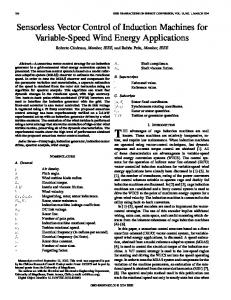
Since the generation of the third-order spatial harmonic has the priority over the fundamental component of the magnetic field, the maximum magnitude of vS1 can be deduced from (22)-(23) and results as follows: (24)
v S 1, max
The behavior of vS1,max is shown in Fig. 1 for the case of 7-phase inverters, but it is similar in case that the number of phases is different. IV.
⎛π⎞ 2 sin ⎜⎜ ⎟⎟ ⎝7⎠
Two PI regulators, (a) and (b), implemented in the reference frame d3-q3, ensure that the d-component of the currents iS3d is constant, whereas the q-component is set to zero. In this way, according to the theoretical analysis presented in Section III, the third-order spatial harmonic of the magnetic field has constant amplitude and its angular speed is three times the speed of the rotor. The bandwidth of these regulators is fundamental to ensure fast tracking of the speed during transients. Therefore it is necessary to accept a compromise between noise rejection (low gain) and tracking accuracy (high gain).
(23)
⎞ ⎟⎟ = vS1,max ⎠
a1
A. Generation of the Third-Order Spatial Harmonic of the Magnetic Field
where the coefficient a1, a2, b1 and b2 are positive quantities depending on the number of the phases M of the motor. Their values are given in Table I for M=5 and M=7.
⎛ Edc −a2 vS 3,ref Edc −b2 vS 3,ref vS1,ref ≤ min⎜⎜ , a1 b1 ⎝
7-phase inverter
⎛π⎞ 2 sin ⎜⎜ ⎟⎟ ⎝5⎠
harmonics of the magnetic field, the second one estimates the motor speed, the third one estimates the position of the reference frame for the field oriented-control whereas the last one is responsible for the tracking of the motor speed and of the current references.
(21)
b1vS1,ref + b2 vS 3,ref ≤ Edc
5-phase inverter
(20)
Inequality (19) shows that the presence of the current component iS3d leads to a small reduction in the available torque-producing current component, IS1q. iS1q ≤ I S2,max − iS21d − iS23d
Coefficient
E dc
0.6 1/b1 0.4
CONTROL SCHEME
0.2
The block diagram of the proposed control scheme is shown in Fig. 2. As can be seen, the input variable is the motor speed, but the scheme, with few modifications, is suitable also for torque control. It is possible to identify four different parts in the scheme of Fig. 2. The first one generates the third-order spatial
0
0.2
0.4 1/b2 0.6 v S 3,ref
E dc
Fig. 1 - Validity domain of vS1,ref as a function of vS3,ref , normalized dividing by the dc-link voltage (the figure refers to the case of 7-phase inverters).
71
PI (d)
i S 1 q , max
iS1q,req
iS1q −
iS1q,ref +
Limitation (g)
−
ωm
+
iS1d iS3d
I S2 , max − i S21 d − i S2 3 d
Anti-windup
PI (e) Backemf comp.
iS1d −
iS1d,ref
v S 1, req
v S 1, ref
v SS1, ref
e j θ1
v S 3 , ref
v S 1, max
PI (f)
+
4
E dc Limitation (h)
v S 1, max
iS1d
e − jθ 1
iS1q
ωm,ref
v S 3 , ref
iS3q −
iS3q,ref = 0
Backemf comp.
iS3d −
iS3d,ref +
e − jθ 3
iS3q
v S 3 , ref
PI (b)
θ1
θ3 1/ 3
d3q3
Inverter dead time compensation
IM
Observer for the rotor flux s ϕ R1
ωm
2
d1q1
3
Third-order harmonic excitation
ωm
i SS1
ab…fg
iS3d
| | ABS
PI (a)
+
1
PWM
v SS3 , ref
e jθ 3
Observer for the rotor
ω3
flux
ϕ Rs 3 ,
based on
the integration of the back emf
Sensorless speed observer
Fig. 2 - Block diagram of the control scheme.
The angular frequency ω3 is obtained by numerically deriving θ3. Since this operation may be affected by noise to some extent, a low-pass filter can be used to smooth the waveform of the output signal.
D. Speed and Current Loops The speed is adjusted by the PI regulator (d), that generates the request of torque-producing current, iS1q,req. The flux-producing current iS1d,ref is set to a constant value, according to the constraint (18). The current references are tracked in turn by the PI regulators (e) and (f). The current iS1,ref is the output of the saturation block (g), which defines an upper and a lower bound for iS1,req. These bounds are calculated according to (20), i.e., considering also the presence of magnetizing current required to generate the third-order spatial harmonic of the magnetic field. A feed-forward signal is added to the output of the PI regulators to balance the back electromotive forces. Finally, the magnitude of the output voltage vector is compared with the admissible voltage given by (24). If the dc-link voltage is not sufficient to synthesize the reference voltage vector, its magnitude is limited by block (g).
C. Flux Observer for the Fundamental Spatial Harmonic of the Magnetic Field The components of the space vector iSS1 are transformed from the stator reference frame to the reference frame d1-q1, which is synchronous and aligned with the rotor flux vector s ϕR1 . The estimation of the rotor flux vector is carried out by using a flux observer, based on the rotor equations (2), (4) and on the measurements of the stator currents. The equation of this observer is as follows: ~ ⎞~ d ϕRS1 ⎛ 1 M (25) + ⎜⎜ − jωm ⎟⎟ ϕRS1 = 1 iSS1 dt τ τ R1 ⎝ R1 ⎠ ~S where ϕR1 is the estimated rotor flux vector and τr1 is the rotor time constant related to the fundamental component of the magnetic field. Equation (25) requires the knowledge of the rotor speed. This quantity is obtained by means of the speed estimator based on the injection of a third-order spatial harmonic of the magnetic field.
V.
EXPERIMENTAL RESULTS
A complete drive system has been built to verify the feasibility of the proposed sensorless drive and some experimental tests have been carried out to assess the performance of the speed observer at low speed. The experimental set-up consists of a seven-phase IGBT inverter and a 4 kW, 7-phase, 4-pole squirrel cage induction motor. 72
TABLE II – SEVEN-PHASE MOTOR PARAMETERS Trated = 24 Nm LS1 = 180 Is,max = 7.5 A(peak) LR1 = 180 IS1d,rated = 3.6 A(peak) M1 = 175 frated = 50 Hz LS3 = 24 RS = 1.1 Ω LR3 = 24 RR1 = 1.0 Ω M3 = 19 RR3 = 0.8 Ω p = 2
null, because the magnetizing current is necessary to sustain the fundamental and the third spatial harmonic of the magnetic field. During the transient, as expected, the stator current is remarkably distorted by the presence of the third spatial harmonic of the magnetic field.
mH mH mH mH mH mH
Fig. 4 shows the behavior during a speed reversal from +100 to -100 rpm. As can be seen, the performance of the observer is acceptable even during the crossing of the point at zero speed. The waveform of the signal corresponding to the phase angle of the rotor flux vector ϕRS 3 is regular and without discontinuities.
The parameters of the motors are shown in Table II. The drive is equipped with an encoder and therefore it is possible to compare the estimated and the real speed.
Figs. 5 and 6 show the behavior of the drive at 20 rpm, corresponding to an electrical frequency of 0.6 Hz, respectively without and with dead-time compensation.
To obtain an acceptable behavior of the sensorless drive, the magnetizing current iS3d, responsible for the third-order spatial field harmonics, has been set equal to 30% of the IS1d,rated.
As can be seen, the dead-time compensation drastically improves the behavior of the drive at very low speed. In fact, in Fig. 5, although the average value of the estimated speed is substantially correct, the speed waveform shows some irregularities, which are oscillations of ±10 rpm in the worst case. In Fig. 6, this problems is remarkably reduced. The estimated angle θ3 has a regular saw-tooth waveform and the
Fig. 3 shows a start-up transient of the drive from 0 to 100 rpm, when the speed set-point has the waveform of a ramp. Trace 1 is the measured speed, whereas trace 2 is the estimated phase angle of the rotor flux vector ϕRS 3 , i.e., θ3. Finally, the third trace is the stator current. When the motor is at standstill, the stator current is not
1
1
2
3
2
3
Fig. 3 - Behavior of the observer during a start-up transient of the drive from 0 to 100 rpm. 1) Measured motor speed (100 rpm/div). 2) Estimated angle θ3 (180 degree/div). 3) Stator current (5 A/div).
Fig. 4 - Behavior of the observer during a speed reversal of the drive from +100 to -100 rpm. . 1) Measured motor speed (100 rpm/div). 2) Estimated angle θ3 (180 degree/div). 3) Stator current (10 A/div).
1
1 2
2
3
3
Fig. 5 - Behavior of the observer without dead-time compensation during a start-up transient of the drive from 0 to 20 rpm. . 1) Measured motor speed (100 rpm/div). 2) Estimated angle θ3 (180 degree/div). 3) Sator current (5 A/div).
Fig. 6 - Behavior of the observer with dead-time compensation during a start-up transient of the drive from 0 to 20 rpm. . 1) Measured motor speed (100 rpm/div). 2) Estimated angle θ3 (180 degree/div). 3) Stator current (5 A/div).
73
drive behavior is overall satisfactory.
Proc. of PESC, 2003, pp. 1475-1480. [10] K.K. Mohapatra, R.S. Kanchan, M.R. Baiju, P.N. Tekwani, K. Gopakumar, “Independent field-oriented control of two split-phase induction motors from a single six-phase inverter,” IEEE Trans. on Industrial Electronics, vol. 52, no. 5, 2005, pp. 1372- 1382. [11] L. Parsa, H. A. Toliyat, “Five-phase permanent-magnet motor drives,” IEEE Trans. on Industry Applications, Vol. 41, No. 1, Jan./Feb. 2005, pp. 30-37. [12] L. Parsa, N. Kim and H. Toliyat, “ Field Weakening Operation of a High Torque Density Five Phase Permanent Magnet Motor Drive,” IEEE IEMDC, May 15-18, 2005, pp. 1507 - 1512. [13] L. Parsa, H. A. Toliyat, "Sensorless direct torque control of fivephase interior permanent-magnet motor Drives, " IEEE Trans. on Industry Applications, Vol. 43, No. 4, July/Aug. 2007. [14] C. Olivieri, G. Fabri, M. Tursini, "Sensorless control of five-phase brushless dc motors", Proc. of SLED 2010, 9-10 July 2010, Padova, Italy, pp. 24-31. [15] H. Xu, H.A. Toliyat, L.J.Petersen, “Rotor field oriented control of five-phase induction motor with the combined fundamental and third harmonic currents,” in Proc. of IEEE APEC, 2001, pp. 392-398. [16] [H. Xu, H.A. Toliyat, L.J.Petersen, “Five-phase induction motor drives with DSP-based control system,” IEEE Trans. on Power Electron., Vol. 17, No. 4, 2002, pp. 524-533. [17] H. Abu-Rub, M. R. Khan, A. Iqbal, SK. M. Ahmed, "MRAS-based sensorless Control of a five-phase induction motor drive with a predictive adaptive model," Proc. of ISIE 2010, 4-7 July 2010, Bari, Italy, pp. 3089-3094 [18] M. A. Fnaiech, F. Betin, G. A. Capolino, "MRAS applied to sensorless control of a six phase induction machine," Proc. of ICIT 2010, 14-17 March 2010, Viña del Mar, Cile, pp.1519-1524. [19] L. Zheng, J. E. Fletcher, B. W. Williams, and X. He , "A novel direct torque control scheme for a sensorless five-phase induction motor drive", IEEE Trans. on Industrial Electronics, Vol. 58, No. 2, Feb. 2011, pp. 503-513. [20] D. Casadei, D. Dujic, E. Levi, G. Serra, A. Tani, L. Zarri, “General modulation strategy for seven-phase inverters with independent control of multiple voltage space vectors,” IEEE Trans. on Industrial Electronics, Vol. 23, No. 2, May 2008, pp.1921-1932. [21] A. Lega, M. Mengoni, G. Serra, A. Tani, L. Zarri, “Space vector modulation for multiphase inverters based on a space partitioning algorithm,” IEEE Trans. on Industrial Electronics, Vol. 56, No. 10, October 2009, pp. 4119-4131. [22] J. Holtz, “Sensorless control of induction motor drives,” Proceedings of the IEEE, 90(8):1359-1394, August 2002. [23] J. Holtz, “Sensorless control of induction machine – With or without signal injection?, ” IEEE Trans. on Industrial Electronics, Vol. 53, No. 1, 2006, pp. 7-30.
The non-sinusoidal waveform of the stator current, due to the presence of the third order harmonic, is particularly evident in the third trace of both Figs. 5 and 6. VI.
CONCLUSION
A sensorless rotor-flux-oriented control scheme for multiphase induction motor drives has been presented. The proposed control scheme is based on a novel speed observer that exploits the capability of multiphase drive to control the third-order spatial harmonics of the magnetic field. The feasibility of the electric drive has been verified by means of a prototype of seven-phase induction motor. The drive has exhibited a regular operation for electrical frequencies down to 0.6 Hz. REFERENCES [1] [2]
[3]
[4]
[5]
[6]
[7]
[8]
[9]
L. Parsa, “On advantages of multi-phase machines,” in Proc. of IEEE IECON, 2005, pp. 1574-1579. E. Levi, R. Bojoi, F. Profumo, H.A. Toliyat, S. Williamson, “Multiphase induction motor drives – a technology status review,” IET Electr. Power Appl., vol. 1, no.4, pp. 489-516, July 2007. G.K. Singh, K. Nam, S.K. Lim, “A simple indirect field-oriented control scheme for multiphase induction machine,” IEEE Trans. on Industrial Electronics, vol. 52, no. 4, 2005, pp. 1177- 1184. E. Levi, M. Jones, S.N. Vukosavic, “Even-phase multi-motor vector controlled drive with single inverter supply and series connection of stator windings,” IEE Proc.-Electr. Power Appl., vol. 150, no. 5, 2003, pp. 580-590. A. Iqbal, S. Moinuddin, M.R. Khan, I.Ashraf, “Indirect rotor flux oriented control of a seven-phase induction motor drive,” Proc. of IEEE ICIT 2006, 15-17 Dec. 2006, pp. 440 - 445. D. Casadei, M. Mengoni, G. Serra, A. Tani and L. Zarri, “SevenPhase Induction Motor Drive Based on Stator Flux Vector Control,” in Proc. of SPEEDAM 2008, 11-13 June 2008, Ischia, Italy, pp.113119. F. Locment, E. Semail, X. Kestelyn, “Vectorial Approach-Based Control of a Seven-Phase Axial Flux Machine Designed for Fault Operation,” IEEE Trans. on Ind. Electronics, Vol. 55, No. 10, Oct. 2008, pp. 3682 - 3691. R. Bojoi, M. Lazzari, F. Profumo, A. Tenconi, “Digital field oriented control for dual three-phase induction motor drives,” IEEE Trans. on Industrial Applications, Vol. 39, no. 3, 2003, pp. 752-760. R. Bojoi, F. Profumo, A. Tenconi, “Digital synchronous frame current regulation for dual three-phase induction motor drives,” in
74