SAPIR: Supervised and Adaptive Programming of Industrial Robots B. Solvang
P. Korondi, G. Sziebig
Narvik University College Department of Industrial Engineering Lodve Langes gt., 2 – 8505 Narvik, Norway
[email protected]
Budapest University of Technology and Economics Department of Automation and Applied Informatics Goldmann Gy¨orgy t´er, 3 – 1111 Budapest, Hungary
[email protected]
N. Ando National Institute of Advanced Industrial Science and Technology Chiyoda-ku, 100 – 8921 Tokyo, Japan
[email protected] Abstract— Cast parts have inconsistent geometry and grinding and deburring operations is to be carried out based on individual observation of every single workpiece. Normally, these operations are carried out manually by humans. However, due to the health risk associated with the grinding process, there is a strong incentive to explore new automated solutions. The industrial robot is viewed as a strong component for this job. Programming industrial robots is traditionally done by Teach or Offline programming methodologies. Both methods encounter problems in grinding/deburring operations. In traditional Offline programming the robot path is generated from a CAD model of the workpiece. This CAD model holds no information on the irregularities (burrs) and then the necessary path cannot be created. This paper presents a new approach for supervised robot programming, which allows new field of application of industrial robots. In the near future, automatization of manufacturing processes with industrial robots in small and medium sized enterprise would be common. Instead of a costly, but fully automated solution, which works only from CAD model of workpiece and does not provide 100% satisfying result, an operator is involved in robot programming. The result is a 90% automated solution with the expertise of the worker. This interactive vision-based robot programming adds the required information into the Offline programming environment. Thus, location and shape of any irregularities can be identified and the necessary deburring path created.
I. I NTRODUCTION Many manufacturing processes leave irregularities (burrs) on the surface of its workpiece. Burrs are often triangular in shape and is found after casting, forging, welding, and shearing of sheet metals [1]. Burrs are often identified and removed by human operators using a chip removal process known as manual grinding. Manual grinding often means hard and monotonous work and the workers need to protect themselves by wearing goggles, gloves and earmuffs, etc. [2]. Grinding is often carried out at a final stage in the manufacturing process where the workpiece is expected to reach its end-geometry. Any manufacturing error at this stage could be very costly and even lead to dismissal of the entire workpiece. Not accounting for possible operator errors the deburring process itself is said
Fig. 1.
Concept of SAPIR
to add up to 10% of the total manufacturing cost [1]. Due to the health risk associated with grinding and the possible added cost from operator errors there is a strong incentive to explore new automated solutions. The industrial robot is viewed as a strong component for this job. New market opportunity for industrial robots are the small and medium sized enterprises. These companies can not afford a fully automated solution for above mentioned problems. Not only because of high prices of industrial robots, but the scalability and flexibility of the automated systems are low. A small company will never have money for whole manufacturing chain, only step by step growth is conceivable. The flexibility could be solved by using open source and open architecture systems. An automated system can not fully replace a worker in the above mentioned situations. The expertise of the worker can be added to manufacturing process, which results a 90% automated system. The workers’ eye is replaced with a camera and the workers’ arm is replaced with the industrial robot. This concept can be seen in Figure 1. Programming industrial robots is traditionally done by the Teach or the Offline programming methodologies. However both methods encounter problems in grinding/deburring oper-
1-4244-1148-3/07/$25.00 ©2007 IEEE. 281 Authorized licensed use limited to: UNIVERSITY OF TOKYO. Downloaded on September 23, 2009 at 09:25 from IEEE Xplore. Restrictions apply.
INES 2007 • 11th International Conference on Intelligent Engineering Systems • 29 June – 1 July, 2007 • Budapest, Hungary
Fig. 2.
System overview
ations. The Teach method is time-consuming since it requires the operator to manually define all poses (robot end-effector position and orientation) on the workpiece. In traditional Offline programming the robot path is generated from a CAD model of the workpiece. This CAD model holds no information on the irregularities (burrs) and then the necessary path cannot be created. Vision based robot programming adds information of the real workpiece into the Offline programming environment. Thus, location and shape of any irregularities can be identified and the necessary deburring path created. The organization of the paper is as follows: Section II describes the concept and overview of the path planning program. Section III–V presents the components of the system. In Section VI experimental test results are shown. Section VII concludes the paper. II. S YSTEM OVERVIEW Programming a robot can be done by various methodologies as seen before. The best way and probably the most used is the offline programming methodology. With offline programming the time consuming teaching can be skipped, but without knowledge of real world new problems rose. Newer types of offline programming tools were developed to model the environment in the virtual reality and also help programmers with robot simulations. Line text editor based offline programming tools are replaced with 3D virtual reality simulators, where robot movements are designed, simulated. In the virtual reality the robot real working environment is also modeled. High precision measurement of the environment is needed to create good quality program code. This measurement can not be automated and the punctuality of the overall system highly relies on this step. In virtual reality the robot stands on a smooth plane and the workspace where the robot interacts is also a smooth plane. But in the real world this can not be granted, some simplifications must be done to limit system complexity. A little modification in the environment must be also traced in the virtual environment. In the virtual environment the robot movement is planned and the movement is stored in robot program, which can be later uploaded to the robot. The generated robot program code is hard to read and still needs
post processing step. The post processing step compiles the source code to robot code, which is called machine code. The above described methodology is used almost in all of the new type offline programming tools [3] [4] [5]. This makes robot programming faster than teaching, but not so accurate. Instead of spending hours of measuring the real world, the same result can be achieved when only the workpiece position is used for calculations. The idea behind this, that why would be the position of tables, machines important for the robot, when the robot is only interacting with the workpiece. Only the origo and the coordinate system of the workpiece are important for the robot. The origo of workpiece can be calculated with much type of measuring technologies. The technologies can be split into two groups; the contact (force feedback, mechanical probing) and the contact less (electromagnetic feedback, ultrasonic sensing, thermal sensing or vision based) technologies. The contact based technologies are hard to automate and usually relay on a contact less technology, but this combination provides high precision. The more accurate contact less technology is used a rapidly rising price must be paid. Using a camera as vision based contact less measuring is not unfamiliar solution. In industrial environment it is preferably used only as a second sensor, supporting probably a laser based measuring system. With a help of an operator a camera based system becomes very powerful and remains fast, simple and cheap. The solution for lack of offline programming tools is the well prepared input of the real workpiece and the preprocessed robot task. In this case the offline programming tool needs only to run a simulation without need of operator interaction. Well prepared input of real workpiece can be achieved by using a camera as a contact less measuring system and the robot task can also be defined on the workpiece based on the image of camera. The operator is only involved in defining the task, which is drawing lines and curves on the 2D image of the workpiece. This is less complicated than instructing the robot in the offline programming tool. After the simulation in the offline programming tool the robot program is compiled to machine code. This complied code can be directly uploaded to the robot. In industry remote management is a key task and the current ABB (Asea Brown Boveri) S3 (Serial 3) controller did not support this. Using the ADLP-10 (ABB Data Link Protocol 10) and ARAP (ABB Robot Application Protocol) the remote operability was also solved. A. System components The proposed system, which can be seen in Figure 2, operates as mentioned above (Section II). The system can be split into three parts. The first part (Section III) creates the robot task (can also be called robot 2D path, robot moves along this) from the image, acquired by the camera. The goal is to reach the optimum in accuracy and complexity; the robot moves along points, which describes a geometrical form. This form can be a line, described by a start and an end point, but it can be also a Bezier curve described by 500 or more points. It is
282 Authorized licensed use limited to: UNIVERSITY OF TOKYO. Downloaded on September 23, 2009 at 09:25 from IEEE Xplore. Restrictions apply.
B. Solvang, P. Korondi, G. Sziebig, N. Ando • SAPIR: Supervised and Adaptive Programming of Industrial Robots
the operator’s role to make the decision. Using an operator here is a simplification, but not in the mean of retardation of quality. Instead of accuracy drop, the operator makes the system as accurate (or more) as it could be with using teaching or online programming, but without the time consumption. The simplification makes robot programming not absolutely automated, but it can be done remotely, far away from the robot. The scope of the paper is to create a vision-based, cheap and easily useable robot programming environment. If we would like to use a laser sensor measuring the origo of a workpiece, the system would become totally automated, but the total cost of ownership would be much higher. The second part (Section IV) uses an existing robot simulation solution for the design and offline programming of complex workplaces fitted with several systems, called IGRIP (Interactive Graphics Robot Instruction Program) and the ABB machine code compiler called OLP3 (Offline Programming 3). The workpiece data and CAD (Computer Aided Design) model is imported to the virtual environment in IGRIP and the simulation is run there. The source code provided by IGRIP is complied by OLP3 to machine code. The detailed description of IGRIP can be found at [6]. The third part (Section V) makes the system remote useable. The following subsections introduce the three parts, in the same sequence as mentioned above.
Fig. 3.
2D track detector use-case diagram
Fig. 4.
Sample screen of 2D track detector
III. 2D TRACK DETECTOR The goal of the application was already presented in the previous section, now the details and the transformation steps (from raw image to 2D workpiece coordinates) will be presented. In Figure 3 the application use-case diagram can be seen. In this picture the transformation steps can be clearly identified. The program starts with an initial screen, a sample screen can be seen in Figure 4. After choosing the input image source, the image is shown in the left part of the application, in the Image from camera box. If it is a live video or an IP camera the live video is shown. We can stop the video whenever we want, and process the actual image shown in the Input image box. The processed image is shown in the right part of application in the Processed image box. The process means that the picture is sent through image filters, and the resulting image is shown in the Processed image box. The image processing steps, algorithms and filters are presented in Section III-A. If we are satisfied with the image processing, we can step forward with pushing View in Window button, or we can start the whole process from the beginning to get a better result with tuning some parameters of image processing. A sample screen can be seen in Figure 5. The View Window shows the same picture as in the Processed image box, but in full size. If the picture does not fit in the screen it can be resized, or even cropped. But every modification in the picture resets all curves and lines, reference points and the origo of the workpiece. The function
Fig. 5.
Sample screen of view window
283 Authorized licensed use limited to: UNIVERSITY OF TOKYO. Downloaded on September 23, 2009 at 09:25 from IEEE Xplore. Restrictions apply.
INES 2007 • 11th International Conference on Intelligent Engineering Systems • 29 June – 1 July, 2007 • Budapest, Hungary
can be accessed by clicking with the right mouse button on the picture. In the View Window the operator can identify the errors of the workpiece and can instruct the robot for deburring parts of workpiece by creating lines curves and region for robot movement. The line, curve and region functions can be selected from the menu on the bottom of the window. A status box instructs the operator what to do and how many points are needed for one line or curve or region. The reference points (also the reference distance) are also set up through the menu. After setting up the reference distance, the image is rotated to be parallel with the window. The origo can be set up right after the reference distance is set. A sample screen of the View Window is shown in Figure 5. The following geometrical figures can be created on the surface of the workpiece: • Line: contains one start and one end point • Curve: contains four points, one start and one end point, and two control points (Represented as a Bezier curve) • Curves: contains connected curves, connection on end and start point • Region: contains at least three points By clicking with the right mouse button on one point of a line or curve or region, the geometrical figure can be deleted or the thickness of the line can be modified. This application does not know anything of the CAD model of the workpiece; it is only for identifying errors. The 3D coordinate generation is done by IGRIP, which is introduced in Section IV. However it is possible to match the workpiece with the original CAD model. The opacity of View Window can be modified from menu, and the window can be moved over the CAD modeler (ex.: Pro/E). The final step before the 2D coordinates will be generated is to set up the tool diameter, and set the resolution of steps for each line. Step resolution means that a line will be split to points, and the distance between these points is the step resolution in millimeters. There is also a step accuracy parameter that can not be modified. Step accuracy parameter shows the operator the maximum of step resolution. This parameter is defined when the reference distance and reference points are set. The distance between the reference points on the screen and the distance of reference point on the real workpiece are divided and the result is the step accuracy. When all parameters are set up correctly and meets the required accuracy; by pushing the save button the 2D coordinate path will be generated in the program directory (positions.txt). Also a configuration file (config.txt) is generated, which is used in IGRIP (Section IV). The configuration file contains parameters of step accuracy, tool size and workpiece information.
(a) Input image from source
(c) Sharpened image
(b) Grayscale image
(d) Edge detected image
(e) Inverted image Fig. 6.
Image processing sequence
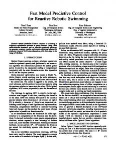
The sequence starts with a grayscale conversation, this step can not be left out, because it is faster and easier to apply filters to a grayscale image. A grayscale image only contains one byte information per pixel, what is great reduction compared to three byte per pixel. The next step is the sharpening filter. This is a pre-processing step for the edge detection. Sharpening is also a convolution filter, and can be given with its filter matrix.
A. Image processing
With a sharpening filter, the contour of the objects in the image is accentuated. Other type of pre-processing filters could be also applied, but the sharpen filter is the most commonly used. For special workpieces (special surface material), there could be a better solution, but it needs individual experiments. Even in special cases the sharpen filter does not provide the best result, this fact is acceptable. In this sequence the Canny edge detector is used. There exists much kind of edge detectors, but our experiments shows that, this type is the best for error detection. The last step in our sequence is the inverting. This step could be left out, if the black based edge detected image is better for the operator.
The goal of the image processing in 2D track detector is to reveal the errors, show the differences to the operator. This can be achieved by using sequence of image filters. The sequence steps can be seen in Figure 6.
Previous work of authors (DIMAN: Distributed Image Analyzer) [7], made a stable background of the implementation of the image processing steps.
284 Authorized licensed use limited to: UNIVERSITY OF TOKYO. Downloaded on September 23, 2009 at 09:25 from IEEE Xplore. Restrictions apply.
B. Solvang, P. Korondi, G. Sziebig, N. Ando • SAPIR: Supervised and Adaptive Programming of Industrial Robots
Fig. 7.
Fig. 8.
Simulation work cell
Models in simulation work cell
IV. IGRIP GSL (G RAPHICS S IMULATION L ANGUAGE ) P ROGRAM The result of the previous section was the 2D coordinates of deburring processes. In this section the 2D coordinates will be transformed to 3D real world coordinates. The 2D– 3D mapping is based on the CAD model of the workpiece. IGRIP is a powerful robot simulation tool, where complete robot manufacturing cell can be constructed and controlled in the virtual reality. A detailed introduction to IGRIP can be found at [6]. In IGRIP a simulation work cell was constructed. In default, IGRIP has much type of built in robots, tools, objects. An ABB IRB 2000 robot and a table were imported to the simulation work cell. The work cell can be seen in Figure 7. As the 2D–3D mapping is based on the original CAD model of the workpiece, these models needed to be imported to IGRIP simulator. Three different kinds of workpieces were manufactured for experimental tests, so these three models were used. The models were placed on the table, where the robot can reach them. The models can be seen in Figure 8. Simulations can be started by operator or it can be instructed from command line. Command line execution of simulations is faster, but it is not spectacular and harder to debug. The 2D–3D mapping could be automated (see sentence above), but in the experimental stage it is important to see the results and using
an operator in experimental stage is acceptable. However the use of the operator is only limited to start the simulation. Graphics Simulation Language (GSL) was used to control a simulation. GSL provides many commands for robot controlling and simulation of whole work cells (Movement of robot joints, movement of tool center point (TCP), I/O channel interaction, etc.). A detailed introduction to GSL language can be found at [8]. The GSL program simulates a ”hit and fall back” force sensor. Every point of the 2D coordinates is checked against the workpiece surface. A grinding pen is attached to the robot arm, and the robot tries to reach the surface of the workpiece from the predefined 2D coordinate. If the robot hits the surface, the 3D position is stored. The hit in simulation environment means, that there is a collision in the simulation work cell. The colliding model parts are painted in red. In real life this hit could be measured via force sensors. In case of a plain surface workpiece, the algorithm will stop, because there is no surface change (No change in depth coordinates). In case of a workpiece, where are drops or spurs in the surface, the above described ”hit and fallback” algorithm does not provide the best result. This is because the robot approaches the workpiece always from the top. A post processing step is needed to correct the ”hit and fallback” algorithm. A function searches for surface changes in the stored 3D coordinates. If it identifies a change, the robot moves to the specified position and tries to rotate the robot arm’s tool center point to get the maximum depth in that position. The rotation is based on the position of the current 3D coordinate and the next 3D coordinate in the row. From the 3D points the x and y coordinates are used for calculation of the rotation and the depth (z) is left out. The z coordinate is used after the rotation of X base is evaluated. The z coordinate defines the direction of Y base rotation. After the post processing step the 3D coordinates are saved in a robot coordinate file. At the same time, the corresponding robot program is generated. Real life coordinates means that the origo of the system is in the base of the robot. V. ROBOT C ONTROLLER The final step of robot programming is the communication with the robot. The ABB IRB 2000 robot has an S3 M91 type robot controller. This controller can be instructed via RS232C serial port. The previously introduced Offline Programming 3 (OLP3) has the capability of uploading, downloading, compiling and decompiling robot programs, but it lacks of remote operation mode. The OLP3 can not be used to remotely monitor the state of the robot, read register values, tool center point values, frame values, etc. In industrial and experimental environment, the remote control and monitoring is a key task [9] [10] [11], and all the programs that were introduced in the previous sections allows this operation mode. This justifies the need for the Robot Controller program. However the OLP3 must be used for robot program compiling. The Robot Controller currently runs only in local mode, because of security reasons.
285 Authorized licensed use limited to: UNIVERSITY OF TOKYO. Downloaded on September 23, 2009 at 09:25 from IEEE Xplore. Restrictions apply.
INES 2007 • 11th International Conference on Intelligent Engineering Systems • 29 June – 1 July, 2007 • Budapest, Hungary TABLE I ACCURACY OF IMAGE PROCESSING Web camera Test 1: ΔX ΔY Test 2: ΔX ΔY Test 3: ΔX ΔY Overall
square 0.87 mm 0.29 mm lines 2.57 mm 0.68 mm points 0.34 mm 1.59 mm
Digital camera Test 1: ΔX ΔY Test 2: ΔX ΔY Test 3: ΔX ΔY Overall
1.06 mm
square 0.83 mm 0.44 mm lines 0.72 mm 0.16 mm points 0.36 mm 0.21 mm 0.45 mm
VII. C ONCLUSION Fig. 9.
Robot Controller main window
The communication over the RS232C serial port (or so called COM port) is based on a standardized protocol; in the case of ABB S3 controller it is called ADLP-10 (ABB Data Link Protocol 10). The lack of protocol description made the implementing task hard. The OLP3 communication with the robot controller was eavesdropped and from analyzing the messages sent from PC to controller and back, the structure of messages, meaning of bytes were revealed. Not all messages were understandable, but the main functions (program downloading, uploading, erasing, starting, stopping, reading register values, etc.) are functional. The main window of Robot Controller is shown in Figure 9. VI. E XPERIMENTAL TEST The test of the overall system can be split into two parts. The first part test the accuracy of the interactive vision-based path planning program, the second part test the robot positioning control system. To measure the effect of the barrel/pincushion distortion and chromatic aberration of the cameras, photos were taken of drawings, which are drawn on a millimeter paper. Three different kind of drawings with two different kind of camera were used. The first camera is a normal web camera (640*480 pixels, 1.3 Megapixel) the second camera is a normal compact digital camera (2856*2142 pixels, 6.1 Megapixel). The pictures was taken from the same height (80 cm). The taken pictures were enlarged to the same resolution (3900*2925 pixels) and after the operator identified the lines and curves on the drawings the robot path data was matched with the original drawing distances on the millimeter papers. The measurement results can be seen in Table I. The measurement of robot positioning control system was done by instructing the robot, drawing a square on a millimeter paper. The square’s corners were programmed to the robot by teaching. The robot program was repeated 100 times and the accuracy of the robot drawing was measured in the corners. The result showed an accuracy of 0.125 mm, which is the same as provided by the manufacturer.
The proposed system meets the requirements that were set up against it. SAPIR makes robot programming cheap, scalable and flexible, which is important for small and medium sized enterprises. The proposed system is accurate enough for the application of grinding and deburring. The accuracy of the system can be made more punctual with using better camera system. Remote operation of system is also achieved by SAPIR. Acknowledgments The authors wish to thank the National Science Research Fund (OTKA K62836), Control Research Group and J´anos Bolyai Research Scholarship of Hungarian Academy of Science for their financial support and the support stemming from the Intergovernmental S & T Cooperation Program. R EFERENCES [1] S. Kalpakjian and S. R. Schmid., Manufacturing Engineering and Technology. Pearson Education, 2006. [2] T. Thomessen, T. K. Lien, and B. Solvang, “Robot control system for heavy grinding applications,” in Proc. 30th International Symposium on Robotics, 1999, pp. 33–38. [3] B. Gunnar, “Programming robot welding systems using advanced simulation tools,” Master’s thesis, Lund University, Sweden, 1999. [4] S. Boopathy and V. Radhakrishnan, “An approach to robot off-line programming and simulation for flexible manufacturing systems,” in Proc. IEEE International Conference on Industrial Automation and Control, Jan. 1995, pp. 461–466. [5] E. Freund, D. Rokossa, and J. Rossmann, “Process-oriented approach to an efficient off-line programming of industrial robots,” in Proc. The 24th Annual Conference of the IEEE Industrial Electronics Society (IECON’98), Aug. 1998, pp. 208–213. [6] D. Systemes. (2002) Igrip homepage at dassault systemes. [Online]. Available: http://www.delmia.com/gallery/pdf/DELMIA IGRIP.pdf [7] G. Sziebig, A. Gaudia, P. Korondi, and N. Ando, “Video image processing system for rt-middleware,” in Proc. 7th International Symposium of Hungarian Researchers on Computational Intelligence (HUCI’06), 2006, pp. 461–472. [8] F. S. Cheng, “Simulation approach for designing robotic workcells,” Journal of Engineering Technology, vol. 3, Oct. 2003. [9] A. J. Alvares and L. S. J. R. Jr., “Telerobotics: Methodology for the development of a through-the-internet robotic teleoperated system,” Journal of the Brazilian Society of Mechanical Sciences, vol. 24, pp. 250–258, May 2002. [10] B. Dalton, “A distributed framework for telerobotics,” Master’s thesis, The University of Western Australia, Australia, 2001. [11] S. Rae, “Using telerobotics for remote kinematics experiments,” Master’s thesis, The University of Western Australia, Australia, 2004.
286 Authorized licensed use limited to: UNIVERSITY OF TOKYO. Downloaded on September 23, 2009 at 09:25 from IEEE Xplore. Restrictions apply.