SWCNT Based Interconnect Modeling Using Verilog-AMS Hafizur Rahaman, Debaprasad Das*, and Avishek Sinha Roy** School of VLSI Technology, Bengal Engineering and Science University, Shibpur, India. Email:
[email protected],
[email protected],
[email protected] Abstract In the future sub-nanometer VLSI technology nodes, it has been proposed that carbon nanotube (CNT) is the most promising candidate for replacing copper interconnects. In this paper, the applicability of bundle of single walled carbon nanotube (SWCNT) has been analyzed for three different random distributions of individual CNTs, while taking into account the process variations concerned with the technology. A model is developed to compare the performance of the CNTs for its various distributions and the performance is compared with each other and also with the existing copper technology. The analysis in this paper shows that various statistical distributions of CNTs in SWCNT bundle does not have any significant effect on the delay and hence the performance of SWCNT bundle interconnects. Keywords Carbon Nanotube (CNT), Single-wall Carbon Nanotube (SWCNT), Verilog-AMS. I. Introduction The modern trend in VLSI technology to fabricate VLSI circuits on small chip areas to save space and reduce propagation delays, leads to various problems in copper interconnects which poses very serious threat to VLSI technology. The traditional copper (Cu) based VLSI interconnects will suffer serious problems beyond 45nm technology node as predicted by the International Technology Roadmap for Semiconductors (ITRS) [1]. As the width of Cu wire decreases its resistivity increases significantly due to surface roughness and grain boundary scattering [2] which will lead to significant impact on performance and reliability of VLSI circuits. CNT based interconnect has become the most promising replacement for Cu based interconnect in future VLSI technology in the nanometer regime [3-7] due to its excellent properties [8-10]. CNTs are graphene sheets rolled up into cylinders with diameter of the order of nanometer. Depending on the direction in which CNTs are rolled-up (chirality), they demonstrate either metallic or semi-conducting properties.
* Student author ** Student author
Due to the intrinsically high resistance associated with an isolated SWCNT, technologists have always focused on SWCNT bundles [3, 5]. It is found that CNT based interconnect is best suited for long (>10 µm) interconnects as compared to Cu based interconnect. SWCNT bundle is a bundle of CNTs connected in parallel. The manufacturing process associated with CNT based interconnect faces the challenge in controlling the CNT diameter and spacing [11-13]. The impact of the variation in CNT diameter and spacing on the interconnect delay is vital in evaluating the timing characteristics of future CNT based VLSI interconnects. Due to ineffective control of chirality of nanotubes in the bundle, SWCNT bundles have metallic nanotubes that are randomly distributed within the bundle. With no spatial separation techniques, the metallic nanotubes are distributed with probability Pm = 1/3 since one-third of possible SWCNT chiralities is metallic. So depending on the process conditions the distribution of CNTs in a SWCNT bundle can vary and in accordance with it the performance of CNT interconnect may vary. Hence, it is necessary to model the SWCNT bundle interconnect for various random distributions of CNTs accurately and compare the performances with each other so that we can predict to what extent it affects the CNT interconnect performance. To our knowledge no other work has done the analysis of SWCNT bundle based on various random distributions of CNTs. In this paper, we have successfully modeled the SWCNT bundle for three different random distributions of CNTs and compared the performances with each other. We have also performed modeling and analysis of SWCNT bundle for three different unique distributions of CNTs while taking in account the intra-bundle variation in individual nanotube diameter. It is found that the statistical distribution of CNTs in a SWCNT bundle apparently has very little effect on the performance. In our analysis we have developed Verilog-AMS based model for defining the three interconnect parameters: Resistance, Inductance, and Capacitance. The developed models are used in the Cadence design environment (Virtuoso) for calculating the delay through interconnect. The equation based modeling style provided by Verilog-AMS is useful as it provides 50-100x speed up over SPICE. The paper is organized as follows. In section II the copper and the CNT interconnect model has been discussed, while our work based on random distribution
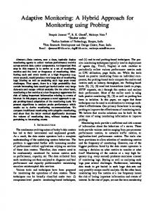
of SWCNTs in a bundle has been analyzed in section III, and at last the results and conclusion are mentioned in sections IV and V, respectively. II. Modeling Copper and CNT Interconnect A. Resistance, Inductance and Capacitance of Cu interconnect The resistance of Cu interconnect is modeled by combined effect of surface and grain boundary scattering as given by the Fuchs-Sondheimer model [14, 15] and the grain boundary resistivity model is based on Maydas and Shatzkes [16]. The self and mutual inductances of Cu interconnect are given by [17, 18] while the capacitance with respect to ground plane is given by [18]. B. Resistance, Inductance and Capacitance of SWCNT The RLC circuit model for SWCNT is shown in Fig. 1. The resistance of a CNT is modeled by three parts. The first and second parts are called contact (RC) and quantum (RQ) resistance, respectively. These two parts are lumped and are independent of CNT length. The third part is called ohmic (RO) resistance which is distributed and is dependent on CNT length [5, 20-22].
(3)
nCNT = Pm ( n nw − n / 2) h h
where Pm is the probability that a nanotube is metallic, nh is the number of nanotubes in the vertical dimension (4) n = h /d h
b
t
and nw is the number of nanotubes in the horizontal dimension (5) n = w /d w
b
t
where dt is the diameter of each nanotube. The resistance of a CNT bundle consisting of nCNT SWCNTs is expressed as [6] (6) R =R /n b
CNT
CNT
The kinetic inductance of the bundle is expressed as [6] (7) LK = L / 4 n b
K
CNT
M
In [24] the magnetic inductance ( Lb ) of the CNT bundle is calculated considering the mutual inductances between the CNTs in a bundle using the partial inductance modeling approach based on the partial element equivalent circuit (PEEC) method. Hence, effective inductance of a SWCNT bundle is (8) L = LK + LM b
b
b
The quantum capacitance of CNT bundle is given by Q (9) C = 4C ⋅ n b
Fig. 1. Equivalent circuit of Single-Wall Carbon Nanotube (SWCNT). The CNTs have kinetic inductance (LK) in addition to the magnetic inductance (LM). The kinetic inductance and the magnetic inductance are given in [23]. Since each CNT has four non-interacting parallel conducting channels, the effective kinetic inductance of a CNT is LK / 4 . So, the total inductance of a CNT is expressed as (1) L = ( L + L / 4) M
CNT
K
The capacitance of SWCNT is modeled by two parts. One is called electrostatic capacitance (CE) and the other one is called quantum capacitance (CQ). The expression for the electrostatic and quantum capacitance is given in [23]. Considering four conducting channels as described before, the total capacitance of a CNT is given by (2) C = C × 4C /(C + 4C ) CNT
E
Q
E
Q
C. Resistance, Inductance and Capacitance of SWCNT bundle If wb and hb are the interconnect width and thickness, respectively, then the total number of metallic nanotubes in a CNT bundle can be expressed as
Q
CNT
The electrostatic capacitance of SWCNT bundle is almost equal to that of Cu wire of same cross-sectional dimensions [6, 22]. D. Modeling process variation Carbon nanotubes are synthesized using several growth techniques such as arc discharge, CVD, laser ablation, and template assisted growth [11], out of which CVD method is the most commercially viable technique. Controlling the diameter of each nanotube in a SWCNT bundle presents one of the most challenging issues in developing nanotube growth methods. When CNTs are grown in a bundle their diameter often varies. It has been found that [12, 13, 19] the diameter variation follows the Gaussian distribution. Typically 33% (Pm=1/3) of CNTs are metallic in a bundle [5]. The rest are semiconducting and do not contribute to any current conduction. The process variations can lead to three types of parameter variation in a CNT bundle: (a) CNT diameter (dt), (b) spacing (inter-CNT distance), and (c) height from the ground plane. The standard deviation (dσ) is taken as 0.1 nm. The distribution of CNTs n(dt) in a bundle is calculated using Gaussian distribution given by (10) 2 1 dt − d µ 1 (10) n ( dt ) = exp − d 2 dσ 2π σ where dµ is the mean diameter which is 1.1 nm in our analysis.
III. Modeling and Analysis based on Random Distribution of SWCNTs In our work we have taken three different random unique distributions of CNTs in a SWCNT bundle. We have considered two cases: in first case the diameter of all the CNTs in the SWCNT bundle is considered to be fixed (1 nm) as illustrated in Fig. 2, while in second case varying diameter of the CNTs are considered where the diameter variation follows the Gaussian distribution with mean diameter of 1.1 nm (see Fig. 3). Fig. 5. Flowchart showing overview of the interconnect modeling.
Fig. 2. Random distribution of SWCNTs in a bundle with all SWCNTs having a fixed diameter.
Fig. 3. Random distribution of SWCNTs of variable diameter in a SWCNT bundle. The circuit used for simulation interconnects is shown in Fig. 4.
of
the
CNT
Fig. 4. Circuit used for simulation (CNT interconnect). Table I: Total number of CNTs in a SWCNT bundle for various technology nodes (Pm=1/3) Technology Number of CNTs node Variable CNT Fixed CNT diameter diameter ( dµ = 1.1 nm) (dt = 1 nm) 16nm 165 178 22nm 315 337 32nm 630 677 45nm 1335 1408
The RLC parameters shown in Fig. 4 are modeled with Verilog-AMS language where the functionality of each parameter is defined separately and is used in Virtuoso for simulation (see Fig. 5). The analysis of SWCNT bundle is carried out for various technology nodes 16nm, 22nm, 32nm and 45nm. Depending on the width and thickness of interconnect, the number of SWCNTs in a SWCNT bundle is found out as shown in Table I. IV. Results The analysis of SWCNT bundle is successfully carried out for three different random distributions of CNTs within a bundle considering fixed diameter of CNTs as well as for CNTs having variable diameter. It has been observed that the resistance of SWCNT bundle remains unchanged for any statistical distribution of CNTs within a bundle (Figs. 6 and 7). The same observation holds true for capacitance and kinetic inductance of CNT bundle. Fig 8 shows the value of capacitance of CNT bundle for various interconnect lengths which are same for both distribution one containing fixed diameter CNT and another containing CNTs having variable diameter. Similarly, Fig. 9, 10 show that there is no variation in the kinetic inductance due to change in distribution of CNTs. The only parameter that changes its value with the change in distribution of CNTs is magnetic inductance which we can observe from [24] where the mutual inductance depends on the variable r i.e., the center-to-center spacing between two nanotubes which will clearly change if we consider various CNT distributions. But from Fig. 11 and 12, we observe that the variation is very little and thus it will have a very small effect on the performance of SWCNT bundle interconnects. This is also found out in our analysis where the time delay of interconnect remains invariable even though the magnetic inductance slightly changes with change in CNT distribution. Fig. 13 shows the plot of ratio of delay of SWCNT bundle to that of Cu wire as a function of interconnect length. The change in delay is very insignificant for any random arrangement of CNTs within the bundle.
V. Conclusion In this work, the analysis of timing delay in SWCNT based nanointerconnect systems considering random distribution of CNTs having both fixed and variable diameter in a SWCNT bundle, has been illustrated. The equivalent circuit for the copper and SWCNT bundle interconnect has been modeled with the aid of VerilogAMS and then simulated in Cadence design environment. The interconnect model developed in Verilog-AMS provides a much better and easier analysis than SPICE counterparts. With the help of Verilog-AMS based model we were also able to study the effect of various unique arrangements of CNTs within a CNT bundle on the performance of SWCNT bundle interconnect. It has been observed that the timing performance of the SWCNT bundle interconnect remains unchanged. Thus it can be concluded from the results that random distributions of CNTs in a SWCNT bundle have negligible effect on the interconnect delay and hence the performance of a SWCNT bundle.
[1]
[2]
[3]
[4]
[5]
[6]
[7]
[8]
[9]
References International Technology Roadmap for Semiconductors (ITRS) reports. [Online]. Available: http://www.itrs.net/reports.html W. Steinhogl, et al., “Size-dependent resistivity of metallic wires in the mesoscopic range”, Phys. Rev. B 66, 075414 (2002). A. Naeemi, R. Sarvari, and J. D. Meindl, “Performance comparison between carbon nanotube and copper interconnects for gigascale integration (GSI),” IEEE Electron Device Lett., vol. 26, no. 2, pp. 84–86, Feb. 2005. N. Srivastava and K. Banerjee, “Performance analysis of carbon nanotube interconnects for VLSI applications”, Proc. IEEE/ACM International Conf. on Computer-aided design, 2005, pp. 383390. A. Nieuwoudt and Y. Massoud, “Evaluating the Impact of Resistance in Carbon Nanotube Bundles for VLSI Interconnect Using Diameter-Dependent Modeling Techniques”, IEEE Trans. Electron Devices, vol. 53, no. 10, Oct. 2006. N. Srivastava, Hong Li, Franz Kreupl, and K. Banerjee, “On the Applicability of Single-Walled Carbon Nanotubes as VLSI Interconnects”, IEEE Trans. Nanotechnology, vol. 8, no. 4, Jul. 2009. Hong Li, et al., “Carbon Nanomaterials: The Ideal Interconnect Technology for Next-Generation ICs,” IEEE Design and Test of Computers, vol. 27, no. 4, pp. 20-31, July/Aug. 2010. B. Q. Wei, et al., “Reliability and Current Carrying Capacity of Carbon Nanotubes,” Applied Physics Letters, vol. 79, no. 8, pp. 1172-1174, 2001. P. G. Collins, et al., “Current Saturation and Electrical Breakdown in Multiwalled Carbon
[10]
[11] [12]
[13]
[14]
[15]
[16] [17]
[18] [19]
[20]
[21]
[22]
[23]
[24]
Nanotubes,” Physical Review Letters, vol. 86, no. 14, pp 3128-3131, 2001. S. Berber, et al., “Unusually High Thermal Conductivity of Carbon Nanotubes,” Physical Review Lett., vol. 84, no. 20, pp. 4613-4616, 2000. Huczko, A. “Synthesis of aligned carbon nanotubes”, Appl. Phys. A 2002, 74,617-638. Chin Li Cheung, Andrea Kurtz, Hongkun Park, and Charles M. Lieber, “Diameter-Controlled Synthesis of Carbon Nanotubes”, J. Phys. Chem. B, 2002, 106, 2429-2433. I. Hinkov et al., “Effect of temperature on carbon nanotube diameter and bundle arrangement: Microscopic and macroscopic analysis”, J. of Appl. Phys., vol. 95, no. 4, pp.2029-2037, Feb. 2004. K. Fuchs, “Conduction electrons in thin metallic films,” Proc. Cambridge phil. Soc., vol. 34, p.100, 1938. E. H. Sondheimer, “The mean free path of electrons in new metals,” Adv. Phys. vol.1, p. 1, 1952. A.F. Mayadas, M. Shatzkes, Phys. Rev., B 1 (1970) 1382. E. B. Rosa and F. W. Grover, “Formulas and tables for the calculation of mutual and self-inductance”, Government Printing Office, 1916. Predictive Technology Model: Interconnect section [Online]. Available: http://ptm.asu.edu/ X. Liu, et al., “Detailed analysis of the mean diameter and diameter distribution of single-wall carbon nanotubes from their optical response,” Physical Review B, vol. 66, 2002. N. Alam, et al., “Performance Comparison and Variability Analysis of CNT Bundle and Cu Interconnects”, Multimedia, Signal Processing and Communication Technologies, 2009. IMPACT '09. International Eric Pop, et al., “Electro-thermal transport in metallic single-wall carbon nanotubes for interconnect applications”, in Proc. IEEE International Electron Devices Meeting, 2005. A. Naeemi and and J. D. Meindl, “Design and Performance Modeling for Single-Walled Carbon Nanotubes as Local, Semiglobal, and Global Interconnects Gigascale Integrated Systems”, IEEE Trans. Electron Devices, vol. 54, no. 1, pp. 26-37, Jan. 2007. P. J. Burke, “Luttinger Liquid Theory as a Model of the Gigahertz Electrical Properties of Carbon Nanotubes,” IEEE Trans. Nanotechnology, vol. 1, no. 3, pp. 119-144, Sep. 2002. A. Nieuwoudt and Y. Massoud, “Understanding the Impact of Inductance in Carbon Nanotube Bundles for VLSI Interconnect Using Scalable Modeling Techniques,” IEEE Trans. Electron Devices, vol. 5, no. 6, pp. 758–765, Nov. 2006.
Fig. 6. Resistance of SWCNT bundle consisting of CNTs having fixed diameter.
Fig. 7. Resistance of SWCNT bundle consisting of CNTs having variable diameter.
Fig. 8. Capacitance of SWCNT bundle.
Fig. 9. Kinetic Inductance of SWCNT bundle consisting of CNTs having fixed diameter.
Fig. 10. Kinetic Inductance of SWCNT bundle consisting of CNTs having variable diameter.
Fig. 11. Magnetic Inductance of SWCNT bundle (CNTs having fixed diameter) for 3 different random distribution of SWCNTs (22 nm technology).
Fig. 12. Magnetic Inductance of SWCNT bundle (CNTs having variable diameter) for 3 different random distribution of SWCNTs (22nm technology).
Fig 13. Ratio of interconnect propagation delay with SWCNT bundle interconnect to that with Cu wire as a function of interconnect length.