This paper presents a method for recursive calculation of the inverse dynamics of real-world robots considering elasticity and gyroscopic effects introduced by ...... [4] W. J. Book, âRecursive Lagrangian dynamics of flexible manipulator arms,â The Int. J. ... [18] R. M. Murray, Z. Li, and S. S. Sastry, A mathematical introduction to.
Proceedings of the 2004 IEEE International Conference on Robotics & Automation New Orleans, LA • April 2004
Symbolic Computation of the Inverse Dynamics of Elastic Joint Robots Robert Höpler and Michael Thümmel Institute of Robotics and Mechatronics DLR Oberpfaffenhofen D-82234 Wessling, Germany [Robert.Hoepler|Michael.Thuemmel]@dlr.de
Abstract— Efficient calculation of the inverse dynamics of robotic mechanisms serves as a basis for a variety of control schemes. Classical algorithms for rigid multibody systems do not apply when more realistic modeling is required. The computational treatment of the emerging non-linear equations augmented by drivetrain dynamics and elasticity imposes various challenges on the algorithmic solutions. This paper presents a method for recursive calculation of the inverse dynamics of real-world robots considering elasticity and gyroscopic effects introduced by the drivetrains. A study of the equations of motion elucidates the demand for analytical derivatives of the dynamics up to a maximum order depending on the number of joints. This problem is solved for the first time by means of higher-order time derivatives of spatial operators proposed by the Spatial Operator Algebra.
I. I NTRODUCTION In the context of robotics inverse dynamics denotes the computation of driving forces from predefined trajectories, e. g., joint positions. The ability to calculate the inverse dynamics is a basic prerequisite for path planning algorithms and feed forward controllers in robotic systems. The computation of the inverse dynamics for rigid robots is a standard task [1]. Using the well-known equations of motion for tree-structured rigid multibody systems (MBS) M(q)¨ q + C(q, q) ˙ + G(q) = τ ,
(1)
and given the desired joint positions q(t) and their derivatives w. r. t. time up to a order of two, the force exerted by the drives τ (t) can be calculated algebraically. When more realistic models including drive dynamics and elasticity in the joints are taken into account the computation becomes more complex: Derivatives of the desired trajectory must be given up to a certain order [2], [3], because the equations of motion must be differentiated several times in order to calculate τ (t). When formulating the dynamics of an elastic robot it is convenient to use the Euler-Lagrange formalism, as shown for the cases of elastic links [4] and elastic joints [5]. This approach reveals the equations’ structure without the necessity to express them explicitly. But, on the other hand, application of the Euler-Lagrange formalism for non trivial robots having many degrees of freedom (dof) imposes several difficulties. While the demanding formulation of the Lagrangian can be handled with special tools one drawback is inherent: depending on the chosen coordinates the formalism results in a small system 0-7803-8232-3/04/$17.00 ©2004 IEEE
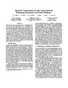
of large equations. Differentiation additionally increases their size and simplification by symbolic computational tools is still hardly tractable. From this point of view it seems favourable to employ a recursive formalism, which leads to more compact equations and is scalable to a large number of dof. Forming the required derivatives of recursive equations is non-trivial for elastic joint robots, but since Rodriguez, et al. have introduced the Spatial Operator Algebra [6] and Park et al., have employed geometric arguments [7], symbolic manipulation of recursive equations has become feasible. This approach has been used, e. g. to linearize forward and inverse dynamics of tree-structured systems by first-order derivatives of rigid MBS equations [8], [9], [10], [11] and to calculate the forward dynamics of a certain class of elastic joint robots [12]. This paper is organized as follows: In Section II the investigated class of robots is presented, rigid link flexible joint robots including the complex gyroscopic couplings between drives and links. The 7-axes DLR light-weight robot is chosen as an example. The properties of the equations of motion and standard solution strategies are described in Section III. Section IV presents a method to differentiate the Newton-Euler equations expressed by spatial operators an arbitrary number of times symbolically. These results are linked to the drivetrain model and lead to a new algorithm discussed in Section V and an interesting closed-form interpretation of expressions from known Lagrangian approaches. Its application to the example system is shown in Section VI and Section VII presents conclusions and ideas for further work. II. I NVESTIGATED ROBOTS The robots considered in this paper have fixed base, rigid links and linear elasticity in the joints. For simplicity the analysis shown is restricted to chain-structured mechanisms, though all arguments given are valid for tree-structured MBS, too. Joints and links are labelled sequentially from base to tip starting from index i = 1 as shown in Fig. 1, where link i follows joint i. Index 0 denotes the robot’s base. Joints are supposed to have one mechanical dof and the total number of joints and dof is N . The drives are rotatory and mounted on the links, and the motor driving joint i is located on link i − 1 as shown in Fig. 1. The drivetrain actuating joint i is modeled by the rotor of drive i controlled by torque τi , driving
4314
0 1
1
1
i-1
i-2 i-1
i
i
i
i+1
i+1
N-1
N
found in, e. g. [16], and results in
N
M(q)¨ q + C(q, q) ˙ + G(q) −K(q − Rθ) ˙ S(q)θ¨ + Crotor (q, q, ˙ θ) T S(q) q¨ + Ccarrier (q, q) ˙ + I θ¨ + Ru
Fig. 1. Schematic view of an N -joint kinematic chain where each link is a gyrostat. Small circles are joints, ellipses rigid links, tilted cylinders are rotors. Numbering ascending from base to tip.
an ideal gear connected to a spring which is connected to link i as shown in Fig. 2. Dissipative effects like bearing friction and gear efficiency as well as nonlinear effects like spring stiffening, hysteresis and backlash are neglected. When the rotors of the drives show axial symmetry, they do not affect the mass distribution of the complete MBS. In consequence the robot can be viewed as a rigid MBS, where each link contains an internal source of angular momentum, i. e. each link is a gyrostat [13].
Fig. 2. Schematic view of drive-train model. From left to right: rotor with inertia I, gear with ratio R, torsional spring with spring constant K, and link.
The method and algorithm presented will be applied to the DLR lightweight robot LBR 2 shown in Fig. 3a. This manipulator arm of approximately 1 m length is able to handle a payload of 8 kg with a total weight as low as 17 kg. The LBR 2 is a good example for practically relevant robots and clearly indicates the problems in computation of the inverse dynamics for non-trivial robots. It is a chain-structured mechanism with seven revolute joints as shown in Fig. 3b. The motors are mounted in the joints, their rotors’ axes of rotation coincide with the joint axes, as depicted in Fig. 3c. The drivetrains are known to be elastic due to harmonic drive reduction gears and torque sensors. Joint stiffnesses are roughly 104 Nm rad . A more detailed description of the LBR 2 can be found in [14], [15].
(a)
(b)
(c)
Fig. 3. DLR lightweight robot LBR 2. (a) Complete manipulator arm, (b) Sketch of kinematic structure, (c) View inside joint showing rotor and drive.
III. C LASSICAL L AGRANGIAN
APPROACH
A Lagrangian derivation of the equations of motion for an elastic joint robot using independent joint variables can be
= u − urotor =u
(2) (3)
= urotor = τ,
(4) (5)
where q/θ ∈ IRN are joint/motor position variables, u/τ ∈ IR N are generalized joint/motor forces. M ∈ IRN ×N is the mass matrix, C ∈ IRN the vector of Coriolis and centrifugal terms of the links, K the diagonal matrix of spring constants, R the diagonal matrix of gear ratios, G the vector of gravitational forces, and S is the matrix of inertial couplings between links and motors. Crotor is due to the spatial motion of the rotors’ angular momentum, Ccarrier corrects for motion of the ’carrier’ links and I is the diagonal matrix of rotor inertias. R, K, and I are supposed to be constant. When the drives are mounted as described in Section II, S is upper triangular [16]: 0 S12 (q1 ) S13 (q1 , q2 ) . . . S1N (q1 , . . . , qN −1 ) 0 0 S23 (q2 ) . . . S2N (q2 , . . . , qN −1 ) .. .. .. .. .. (6) . . . . S=. .. 0 . SN −1N (qN −1 ) 0 0 0 0 0 ... 0 The ith component of Crotor explicitly depends on link variables and θi+1 , . . . , θ˙N Crotor 1 (q, q, ˙ θ˙2 , . . . θ˙N ) Crotor 2 (q, q, ˙ θ˙3 , . . . θ˙N ) .. Crotor = (7) . . C ˙ (q, q, ˙ θ ) rotor N −1
N
˙ CrotorN (q, q)
This model is similar to the one described in [3] but includes the more general case of non constant S and, hence a non-zero Crotor . Besides it shows the dependency on the gear ratios R. For calculation of the inverse dynamics using equations (2)(7) one starts with the N th component equation of (2). Due to (6) and (7) this equation only depends on link variables and one is able to solve for θN . Differentiating this equation twice w. r. t. time gives θ˙N and θ¨N . Now one can solve the N th equation of (5) for τN . Proceeding from tip to base it is possible to solve the second-last equation of (2) for θN −1 using θ˙N and θ¨N . Again this equation needs to be differentiated twice to calculate θ˙N −1 and θ¨N −1 what in (3) (4) turn requires θN and θN and therefore the third and forth derivative of the N th equation of (2). Repeating this way one completes calculating τ1 which requires derivatives of the equations of motion up to order α = 2N and derivatives of the desired joint positions up to order 2(N + 1). Greek index α denotes the number of derivations. This approach results in N very large algebraic equations for the motor forces which are awkward to handle and inefficient for computation. In the following sections a new non-Lagrangian approach is presented, which is amenable to efficient implementation while preserving the structure of the governing equations.
4315
IV. S YMBOLIC H IGHER - ORDER
TIME DERIVATIVES OF
φ2,1 Φ := .. . φN,1
MULTIBODY EQUATIONS
In this section a method is developed to calculate derivatives of equation (2) in a symbolic and recursive manner employing the Spatial Operator Algebra (SOA) [6]. The SOA has proven to be a powerful formalism to derive equations for a wide range of MBS problems from spatial operator identities. It maintains maximum insight into the underlying physics and the structure of the equations, essential for further manipulation and efficient implementation. Key requisites are the notion of spatial vectors ∈ IR6 , a stacked notation of spatial operators [6], [17], and a flexible choice of coordinate representations for kinematics and dynamics equations [9]. Spatial vectors are composed of two vectors ∈ IR3 , where the first one represents rotational and the„second one translational « ω quantities, e. g. spatial velocity V := v , with ω angular and v translational velocity. It turns out that an appropriate coordinate representation of the dynamics is a key issue to obtain compact expressions for higher-order spatial derivatives. The body-fixed representation [13] presents an efficient means, because expressing dynamics w. r. t. a body-fixed frame allows for recursions based on local time derivatives and essential spatial operators remain constant [17]. This leads to simpler construction of the recursions than in [7], so in the analysis below body-fixed representation will be applied. The local derivative of a spatial vector Vx w. r. t. an accelerated frame Fx is defined by ◦
Vx := where
dVx dt
dVx ˜ x Vx −Ω dt
ωx 03
.
can be viewed as derivative w. r. t. a moving but nonrotating frame. The spatial generalization of the tilde-operator ˜b = a × b, a, b ∈ IR3 is used, the spatial cross product a operator [17] defined as � � � � ˜ 03×3 a ˜ := a , where X = X and a, b ∈ IR3 . ˜ a b ˜ b ◦
For further use the notion of the α-times local derivative V (α) is introduced, with α denoting the number of differentiations. The rigid body transformation operator [9], [6] � � i Ri−1 03×3 φi,i−1 := ˜ i−1,i i Ri−1 i Ri−1 −(i) p
relates spatial quantities expressed in local frame Fi−1 located in the joint i − 1 to those expressed in Fi in link i, where i Ri−1 (qi ) and (i) pi−1,i are rotation and displacement from Fi−1 to Fi . The spatial recursions are defined in terms of the stacked operators 06×6 φ2,1 . . . (9) Eφ := .. .. . . φN,N −1 06×6
..
.
..
.. . . · · · φN,N −1 I6×6
which are related by the identity [6]
(10)
(11)
Φ−1 = I6N ×6N − Eφ .
Please note symbols and definitions slightly differ from the original ones introduced by Rodriguez, Jain, and Delgado [6], especially the numbering of bodies is reverted and follows robotics literature. When using a body-fixed dynamics representation and full stacked notation equations (2) and (4) can be expressed as the following recursive Newton-Euler equations (12)
V = Φ∆ ◦
˜ V = Φ(H¨ q − ∆V) ◦
(13)
˙ g ) − V MV + L} ˙ f = Φ {M(V + V T
˜T
(14) (15)
T
u = H f.
The stacked operators used here are defined in the following, a right lower index X [i] or X [i,j] denotes the block matrix corresponding to link i or one pair of links i, j: • spatial velocity V := col{V [i] } • relative link velocity across ith joint ∆[i] := H[i] q˙i and ∆ := col{H[i] q˙i } • joint projection operator H := diag{H[i] , . . . , H[N ] }, the linear mapping between joint and spatial coordinates. « In „ ni case of revolute joints with axis ni it is H[i] = 0 . 3
spatial force f := col{f [i] } ˙ g := col{V ˙ g [i] } • spatial gravitational acceleration V • spatial inertia matrix M := diag(M[1] , . . . , M[N ] ) where � � ˜ i,cmi Ji mi p M[i] := ˜ i,cmi mi I3×3 −mi p is the spatial inertia of link i including the motor mounted on it w. r. t. to frame Fi , where mi is the total mass, Ji the inertia matrix w. r. t. Fi and pi,cmi the vector from Fi to the center of mass. • rotor axis projection operator Hr , that shows the directions of the rotors’ axes and on which link each motor is mounted. In case rotor i is mounted on link i − 1 the operator writes 06 Hr [2] .. .. . . , (16) Hr := .. . Hr [N ] 06 i. e., changing angular momentum L˙ [i] contributes to f [i] . • vector of internal angular momentum of each gyrostatic link L := col{L[i] }. Except for operators M and Φ which are ∈ IR6N ×6N , and H, Hr ∈ IR6N ×N , all stacked spatial entities are ∈ IR6N . For any stacked X ∈ IR6N the stacked tilde operator ˜ denotes a block-diagonal matrix ∈ IR 6N ×6N where X ˜ = diag(X g ] X [1] , . . . , X [N ] ). For a more comprehensive treatment of this notation the reader is referred to, e. g., [9], •
is the absolute time derivative w. r. t. to an „inertial «
frame and the spatial angular velocity of Fx is Ωx := ◦ Vx
(8)
I6×6
4316
[6], [17]. A common approach to account for gravition is to consider the base system accelerated by a gravitational accel◦ ˙ g [0] and the gravitational acceleration eration [1] of V[0] ≡ V ˙ g can be omitted. Important to note is, that H, Hr matrix V and M remain constant in body-fixed representation which simplifies derivatives w. r. t. time drastically. Expanding Φ using (11) leads to the well-known two sweep calculation, one outboard sweep from base to tip (12) and (13) and one tip-to-base inboard sweep (14) and (15). The main idea is to establish a recursion w. r. t. differentiation order α for the standard recursive equations w. r. t. link index i analogously to equations (12)-(15). The goal is to arrive at an algorithm which is amenable to an efficient and straightforward implementation. A. Kinematics derivatives When restricting to the rigid MBS model described by (1) the calculation of the α-times derivative of the dynamics requires derivatives of M and C up to an order of α. As a consequence the spatial velocity V has to be differentiated for α + 1 times. In absence of collision and contact it is possible to obtain derivatives of the equations of motion of arbitrary order what is due to the structure of the underlying smooth kinematics and dynamics equations [18]. To obtain a recursion w. r. t. α we assume the α-times local derivative of V obeys the identity ◦
V
(α)
(17)
= Φ (Aα + Bα ) .
From (12) follow A0 = ∆ = Hq (1)
and B0 = 0
leads to ◦
V(α+1) = Φ The equivalences
˜ φ = −∆E
(19)
˜ φΦ Φ = −Φ∆E
(20)
�
◦ Aα
◦
˜ φ V(α) + − ∆E
◦ Bα
A change in angular momentum ◦ d ˜ [i] L[i] = Ii (Hr [i,j] θ¨j + Ω ˜ [i] Hr [i,j] θ˙j ) (22) L[i] = L[i] + Ω dt expressed conveniently with circle derivative and stacked representation ◦ ˜ L˙ = L + ΩL causes a torque which contributes to the dynamics. There is no need to apply a rigid body transformation from the center of rotor to the center of link, because this pure torque is independent of the point of application. When calculating the MBS dynamics the contribution of each link to the spatial force ◦ ◦ ˜ T MV + ΩL ˜ fδ := MV + L − V (23) allows for a compact expression of the spatial recursion (14), f = ΦT fδ . Analogously to (17) one again can assume ◦
f (α) = ΦT (Cα + Dα )
�
(24)
and for α = 0 follows ◦
C0 = fδ (0)
and D0 = 0 .
Differentiating (23) α-times and using a binomial expansion one arrives at a compact non-recursive ◦
(18)
needed to start the recursion. Differentiating (17) once locally w. r. t. time and using operator identities for the time derivatives of (9) and (10) found in [17] ◦ Eφ ◦
dynamics. Hereby nr j is the rotor axis of rotation and Ij the inertia about nr j . The rotor spatial angular momentum hence is � � Li ˙ . L[i] := Hr [i,j] Ij θj = 03
◦
◦
(25) fδ (α) = MV(α+1) + L(α+1) " # T α � � ◦ ◦ X ◦ ◦ α ˜ (j) MV(α−j) + Ω ˜ (j) L(α−j) . + −V j j=0
Differentiating (24) w. r. t. time � � ◦ ◦ ◦ ◦ (α+1) T T ˜ T (α) f =Φ Cα − E φ ∆ f + Dα
again leads to a symbolic recursion when identifying
.
◦
◦
Cα+1 ≡ Cα = fδ (α+1)
(21)
◦
◦
˜ T f (α) . Dα+1 ≡ Dα − EφT ∆
◦
Aα+1 ≡ Aα = Hq (α+2) ◦
V. R ECURSIVE
◦
˜ φ V(α) + Bα Bα+1 ≡ −∆E formally lead to the desired form of P equation (17). By construction Bα always fulfills Bα = i bα,i where each ◦ ◦ Q (αj ) ˜ ]Eφ V(αi ) with summand is a product bα,i := ki j∈Ji [∆ ki is scalar and Jj ⊂ {0, 1, . . . , α − 1}. This follows from identities (18) and (19). B. Dynamics derivatives If motor j is mounted on link i all of its inertia properties Mr [j] can be added to the link resulting in a total M[i] . The rotor angular momentum relative to the link Li := Ij nrj θ˙j has to be considered separately in order to calculate the correct
ALGORITHM
In this section it is shown how elastic drivetrain and rigid multibody models are combined for computation of the inverse dynamics. A. Combining elastic drivetrain and rigid multibody models A strategy for solution of the complete problem becomes clear when expressions from (2)-(5) are identified in (12)-(15). Combining the latter together and using (22) gives
4317
u = HT ΦT MΦH¨ q ˜ −V ˜ T M)V +HT ΦT (−MΦ∆ ˜ r I θ˙ +HT ΦT Hr I θ¨ + HT ΦT ΩH
(26) (27) (28)
where (26) and (27) are standard factorizations of M and C [8]. Comparing expression (28) with (4) leads to the important operator factorizations of S and Crotor : S(q) = HT ΦT Hr I ˙ = HT ΦT ΩH ˜ r I θ˙ . Crotor (q, q, ˙ θ)
(29) (30)
Algorithm 1 Inverse dynamics algorithm Detect permanent zeros of S(q) from MBS topology Require: S(q) is upper triangular Calc. max. order αmax [i] for each ui from (4) αmax = maxi=1,...,N αmax [i] ◦
V(α) [0] = 06 , α ∈ {0, . . . , αmax + 1} for i=1 to N do /* Outboard sweep */ for α=0 to αmax +1 do ◦ ◦ V(α) [i] = φi,i−1 V(α) [i−1] + Aα[i] + Bα[i] end for end for ◦ (α) f [N +1] = 06 , α ∈ {0, . . . , αmax } for i=N to 1 do /* Inboard sweep */ for α=0 to αmax [i] do
Equation (29) restates (6) in an explicit manner and it obviously results in the upper triangular shape derived in (6) from pure structural arguments. An arbitrary axis of rotation ni is invariant under its generated rotation,« i Ri−1 ni = ni . It „ n follows that φi,i−1 (qi )H[i] = −(i) p˜ i n is independent of i−1,i i qi . This observation shows that row i of the operator product HT ΦT in (29) is independent of qi , thus revealing one more structural property of S(q): Si,j = S(qi+1 , . . . , qj−1 )i,j ,
1