Synchronous Vector control Design of Multilevel Inverters for AC Grid Applications AMARENDRA MATSA
MADHURI A. CHAUDHARI
Department of Electrical Engineering, Viswavarayya National Institute of Technology, Nagpur, India – 440010. E-mail:
[email protected].
Department of Electrical Engineering, Viswavarayya National Institute of Technology, Nagpur, India – 440010. E-mail:
[email protected].
Abstract—This article presents advanced vector control technique for a five-level cascaded H-Bridge inverter for integration of distribution generation based on renewable energy to the power grid. The presented control strategy has designed with SRF PLL and the proposed control plan is completed by setting suitable reference current components for the d and q axis in the control loop of DG, which are given based on the objectives of projected method. The objectives of control technique of DG interface system are employed to enhance the standard of power grid by injection of active and reactive current elements through integration of DG resources to the grid. In this paper an Optimized Space vector pulse width modulation (OSVPWM) control technique of five-level H-Bridge VSI has been conferred support on analysis of voltage and current elements in abc-αβ and αβ-dq special reference frames. High performance of the projection technique indicates with injection of most accessible power from renewable energy resources to power grid, this increases power factor of the grid, and reduces total harmonic distortion (THD) of grid current. The proposed control design is verified with simulations results carried using Matlab/Simulink software to carry out the different operational conditions Keywords— Distributed Generation; Optimized SVPWM; Cascaded H-Bridge Inverter.
I.
INTRODUCTION
The increasing demand for clean, reliable and renewable energy is driving society towards distributed generation (DG) systems. DG technology is of apprehension due to supplying the loads in remote and rural places [1-3], where application of this technology can reduce the necessity to build new transmission lines. In addition, application of DG resources based on renewable energy such as solar and wind leads to decrease the carbon emission and emission of other air pollutants arisen from the conventional coal fired power plants. Generally, power electronic devices are extensively used for the power regulation of DG sources and injection to the grid. Application of these devices organize an opportunity to control different aspects of the system such as active and reactive power sharing between the grid and DG link, creating the sinusoidal voltage at point of common coupling (PCC), and increase the power quality indices of utility grid. The DG concept emerged as a way to integrate different power plants, increasing the DG owner’s security and reliability, and
978-1-4799-8641-5/15/$31.00 ©2015 IEEE
providing additional power quality benefits of the power grid. As a consequence, the control of DG unit should be enhanced to meet the requirements for the power grid. Therefore, design of a control technique, which considers different objectives in the power grid, becomes issue of high attention in DG technology. Ahmed presented various issues related to grid integration of RES keeping in the view of aforesaid trends it becomes necessary to investigate the possible solutions for these issues [4]. The mechanism of harmonic current injection from single-phase grid-connected converters is comprehensively investigated. The measurable impacts from grid voltage, converter commutation, power factor, PWM modulation and control strategy are demonstrated on the harmonic current injection [5]. Rabiul Islam had presented a high-frequency link multilevel cascaded medium-voltage converter, which having the common high-frequency link generates multiple isolated and balanced dc supplies for the converter. This inherently minimizes the voltage imbalance and common mode issues [6]. Edris Pouresmaeil presented a multi objective control scheme based on the dynamic model of three-level, neutral-point-clamped voltage source inverter for integration of distributed generation (DG) resources based on renewable energy resources to the distribution grid [7]. Guofeng had presented a novel control strategy of suppressing dc current injection to the grid for PV inverters is investigated. It is based on the idea of accurately sensing the dc offset voltage of PV inverter output. Since dc component of the inverter output can be eliminated, dc injection to the grid can be effectively suppressed [8]. In this paper, a synchronous vector control design for an optimized SVPWM operated five-level cascaded H-Bridge inverter to interface DG resources to the power grid is presented. Based on the proposed algorithm, a stable operating region for the DG-interfaced converter can be defined, which is the main contribution of the proposed control scheme. The proposed control technique reduces the complexity of the SVPWM. The synchronous reference frame PLL is used, which is the most widely used linear closed-loop PLL. Under the condition of an ideal three-phase equilibrium voltage, the frequency, amplitude and phase of the grid voltage can be
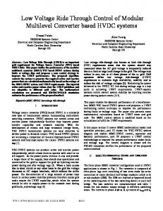
Fig. 1. Schematic Diagram of grid connected DG interface system.
detected quickly and accurately by the SRF-PLL [9], additionally; maximum available active power will be injected from the DG source to the power grid. All the harmonic current components and reactive power of loads can be supplied through the DG link within the defined region. The performance of proposed control technique in DG technology is validated through the Matlab/Simulink during dynamic and steady state operational conditions. The rest of the paper is organized into eight sections. Following the introduction, general schematic diagram of the proposed DG model and steady state analysis of the model is given in Section II. Calculations of reference block components are included in Section.III. Calculation of controller coefficients is described in section IV. A new OSVPVM technique in Section V. Synchronous Space Curve (SSC) approach to represent the area of active and reactive power for proposed DG model is discussed in Section VI. Moreover, simulation results are presented to demonstrate the efficiency and applicability of the developed control strategy in Section VII. Finally, some conclusions are drawn in Section VIII.
can be achieved as 2
(2) , ,
./
1,2,3. .8.
where is the switching function of Five-level cascaded H-Bridge inverter. By applying the Kirchhoff Current Law (KCL) to DC side of inverter (3) Based on equation (3), the equivalent switching state function of interfaced converter can be expressed as; , ,
2
1,2,3. .8
(4)
Equ. (2) to (4) Shows that the value of equivalent voltage depends on the switching function of the interfaced converter. The dynamic equations in matrix form can be expressed as,
II. DISCRIPTION OF THE SYSTEM Fig.1 shows an appropriate plan to control the interfacing system for integration of DG resources to the grid. The dynamic analytical model of the whole DG model should be developed to control grid connected converter. Initially state space equations of proposed model are derived by applying Kirchhoff Voltage law to (Fig.1) model.
0 Where
, ,
(1)
0 0 0
0
0 0
2
(5)
In order to evaluate the performance of control strategy, the model in equation (5) can be transformed to synchronous orthogonal frame rotating at the grid angular velocity. All AC variables in main frequency become DC value. By using parktransformation matrix, the dynamic equations of model can be transformed to D-q frame as,
0
0
0
0 2
(6)
Fig. 2. Inverter current Control loop.
Transfer function of PI controller is,
Eq.(6) can be represented in vector form as
GPI(s) = Kp + Ki /S
0 (7) 0
,
0 0
, ,
0
GS&H(s) = 1/ (sTs +1)
, III.
Sample & Hold is used to change an analog signal to digital (7)for where; signal. Its purpose is to hold the analog value stable a short time while system is performing an operation which takes time.
The transfer function of VSI is,
REFERENCE BLOCK COMPONENTS
should be The reference values of iI D and iI determined to generate active and reactive power according to the maximum available capacity of converter and also make converter capable to compensate all the harmonic current components during the connection of non-liner load into the power grid. By injection of harmonic current components from the DG source, Fundamental component will be supplied through the grid which is pure sinusoidal in nature. (8) (9) Where is q component of load current at fundamental frequency. The reference value of DG control Loop at D-q axis can be obtained as, )
(10)
The equivalent switching state function of interfaced converter can be obtained from eq. (7)
) )
(11) (12)
IV. CALCULATION OF K P AND K I COEFFICIENTS FOR PI CONTROLLER To achieve a fast dynamic response and zero steady state errors, a PI regulator is needed. Fig.2 shows the closed current control loop structure of inverter current. The coefficients of PI controller can be obtained as [10-11]:
GVSI(s) = 1/ (sTpwm +1) Filter block represents the transfer function of L filter. To obtain optimized steady state error the transfer function of PI controller is designed with Siso toolbox from Matlab. This tool has been used in discrete analysis in order to understand how the value of the PI controller has been obtained. The following standard constraints have been taken into account to obtain a good performance of the current controller. The current loop must be stable, hence; the phase margin = 45 degrees and gain margin = 15 dB is chosen. The value of the damping factor will be higher than 0.707, to have an overshoot under 5%. The transfer function of the overall system in open loop is: Gol(s) = GPI(s) * GS&H(s) * GVsi(s)* Gfilter(s) V.
(13)
OPTIMIZED SVPWM TECHNIQUE
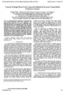
The space vector pulse with modulation (SVPWM) provides superior harmonics capacity, and permits to solve the problem of unbalanced capacitor voltages by using the redundant states in the space voltage vector plane. Many methods have been developed to implement the SVPWM for driving VSI [12-16]. Generally, the SVPWM implementation involves Sector identification, switching vector determination and optimum switching sequence selection for inverter [6-7]. With the new optimized technique for the Space Vector Modulation (SSVPWM) technique the complexity and effort involved in the Space Vector Diagram (SVD) of five-level CHB inverter is reduced. For Five-level inverter, based on the geometrical simplification of SVD the proposed method reduces the number of two – level hexagons to be considered from conventional 36 to 24(18 outer + 6 inner).Fig.3 show the selection of inner and outer region of five level hexagon.
VI.
SYNCHRONOUS SPACE CURVE(SSC) FOR DG MODEL
Due to closed loop control, it is expected that the variables of DG reach to their reference values after the transient time. The steady state analysis of the grid connected DG model defines an acceptable area for the reference currents of DG control loop and injected active and reactive power from the DG link to the grid. Considering that during the steady state condition, voltages at PCC are balanced and sinusoidal, and injected current from the DG is equal to the reference values. 0
(18)
0 0
Fig. 3. Selection of inner and outer regions
The presented OSVPWM is relying on the idea of partitioning of a five-level SVD [Fig. 3] into inner and outer regions. The selectivity of the inner and outer regions depends on the magnitude of Vref. If Vref magnitude is less than 2E, then the inner region is selected; otherwise, outer region is selected. The two-level hexagons within the outer or inner region square measure elite supported the angle θ of the first reference voltage. Selecting a particular hexagon in the outer region depends on angle θ. When an outer hexagon is chosen, a brand new reference vectorVrefo2 is generated; which originates from the center of the outer two-level hexagons. The tip of this new vector coincides with the tip of Vref5.The mapping of all Vrefo2 hexagons is described in Table I. When the inner two-level hexagons (IH) are selected, reference vector Vref5 is mapped to the inner two-level hexagon center reference vector Vrefi2. The appropriate selection of IH depends on angle θ5 and the mapping of all Vrefi2hexagons is described in Table II. The dwell time calculation and switching sequence generation for the selected two-level hexagon can be performed as in the conventional two-level SVPWM technique. Each two-level hexagon is divided into six sectors [17]. The volt-second-balancing equation for this sector is then given by, VrefTs = V1Ta + V2Tb + V0T0
(19) (20)
Where and are the state function of interfaced converter in a stable region then from eq.(18), (19) and (20) we can expressed as, (21) Eq. (21) represents a circle of radius center of (
JD RIN
V DC IDC RIN
JD RIN
and
, 0 . Each DG model has its own SSC which
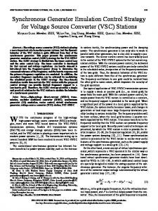
depends on the different parameters.Fig.4 shows the as Consumption area for the active and reactive power of two grid connected loads. As shown in fig.4, DG can supply all the active and reactive power components of load1, which is inside the area of SSC of DG model. But after connection of load2 to the grid, requested power by the load is more than the maximum capacity of DG; then, DG can’t supply all the active and reactive power requested by the loads. In the other words DG can only provide the load power available inside the SSC which is considered as the stable region for the DG operating condition and is designed based on the maximum capacity of interfacing system.
(14)
Where Ts is the sampling interval; and Ta, Tb, T0 are the respective dwell times for the vectors V1, V2 and V0. The values of Ta, Tb and T0 are given by, Ta = Ts x Ma Sin ( -θ) Tb = Ts x Ma Sin θ To = Ts – Ta - Tb where Ma is the modulation index defined as, Ma = √3
(15) (16) (17)
Fig. 4.
Synchronous Space curves at different loads.
TABLE I. Mapping ofVrefo2from Vref5 Hexagon number
Hexagon
VO2α
VO2β
OHk
V5α – 2.598076211E cos{(k-1)Π/9)
V5α – 2.598076211Esin{(k-1)Π/9)
V5α – 3 E cos{(n-1)Π/9)
V5α – 3E sin{(n-1)Π/9)
OHn
k =1, 4, 7,10,13,16. n =2,3,5,6,8,9,11,12,14,15 ,17,18
TABLE II . Mapping ofVrefi2from Vref Hexagon
VI2Β
VI2Α V5α – E cos n
IHn
1
Π
V5α – E sin n
VII. SIMULATION RESULTS Simulation of the presented system is carried to study performance of design controller under different conditions. First, capabilities of DG resources and adaptability of control strategy for management of integrated VSC in providing active, reactive and harmonic current components of different loads are studied. The capabilities of control method on reactive power tracking with constant output active power are considered. In addition, these results are analyzed to give Total Harmonic Distortion (THD) of the utility grid current amid severe varied load conditions. Simulation results are shown in Fig.5 to Fig.8.Fig.5 shows grid current, load current and DG current under different loading conditions. TABLE III. Simulation parameters. Nominal grid voltage(Ph-Ph Rms)
110 V
Rated output power of Inverter
3KW
DC source voltage Grid Frequency Switching frequency
80V 50Hz
Hexagon number n =1.2…6
PCC. During this period DG is supplying current to load as well as grid, Hence grid current is in anti-phase with DG current. At t=0.1 Sec the load is increased to 3KW, which is equal to DG capacity and supplied by DG link only. At t=0.2 Sec; at this load further increased to 5KW, But since DG link can supply only 3KW reaming power is supplied by the grid as seen from waveforms. From the time t=0.3 Sec to 0.4 Sec nonlinear load is of 6KW is constant. The harmonic components are supplied by the DG converter only, hence grid current is sinusoidal. At t=0.4 Sec Entire DG is disconnected, entire power is supplied by the grid only. In order to increase the power quality of grid, DG should generate the total reactive power of loads. Thus, one in all the foremost vital aims of the projected control technique for DG model is achieving unit power factor between grid current and load voltage. The Performance of the control approach is evaluated by Fig.6, Fig.7 and Fig.8 Shows the active power, reactive power variations of Grid, Load and DG link and Grid current THD respectively. VIII. CONCLUSION
2K Hz
The rated active power of DG is assumed be 3KW.From time t=0 sec to t=0.1 sec resistive load of 1KW is connected at
Fig. 5. (a) Grid current
1
Π
This paper investigates a novel synchronous vector control strategy for five-level cascaded H-bridge inverter is developed to enhance Grid interfaced performance, which has adopted typical optimization modulation principles, i.e., optimized
(b) Load current (c) DG current
References [1]
[2]
[3]
Fig. 6. Active powers of DG, Load and Grid [4]
[5]
[6]
Fig. 7. Active powers of DG, Load and Grid [7]
[8]
[9]
[10]
Fig. 8. Grid current THD space vector pulse modulation with reduced complexity and reduces memory required for five level cascaded H-bridge has been implemented. Instead of generating a voltage signal by the standard control structure, the proposed vector control structure outputs a tuning current signal. The proposed DG model can provide the continuous injection of active power in the main frequency, and all the reactive power and harmonic current components of grid-connected nonlinear loads, with a fast dynamic response, through the integration of DG resources into the power grid. The proposed control strategy can be used for the integration of different types of DG resources specially based on renewable energy, as power quality enhancement device in a custom power distribution network.
[11]
[12] [13]
[14]
[15]
[16]
[17]
S. Mendalek N, Al-Haddad K, “Experimental design of a nonlinear control technique for three-phase shunt active power filter,” IEEE Trans Industrial Electronics, vol.57, no.10, pp:3364–75,may 2010. Ma J, Wang X, Zhang Y, Yang Q, Phadke AG,“A novel adaptive current protection scheme for distribution systems with distributed generation,” Int J Electr Power Energy System, , vol.43, no.1, pp:1460-6, sep. 2012. W. Bohrer, M. Carpita, T. Ghiara, L. Puglisi, “A flexible control strategy to interface solar system with privileged load and utility line. Electrotechnical Conference Proceedings. Integrating Research, Industry and Education in Energy and Communication Engineering,” MELECON '89, Mediterranean 11-13, 1989, pp. 25-30. Ahmed Sharique Anees,“Grid Integration of Renewable Energy Sources:Challenges, Issues and Possible Solutions”, Power Electronics (IICPE), 2012 IEEE 5th India International Conference on, Delhi,Dec. 2012, pp: 1 - 6. Keliang Zhou1, Zhipeng Qiu2, Neville R. Watson1, Yonghe Liu1, “Mechanism and elimination of harmonic current injection from singlephase grid-connected PWM converters,” IET Power Electron.,vol.6, no.1, pp. 88–95, jan.2013. Md. Rabiul Islam, Youguang Guo, Senior Member, IEEE, and Jianguo Zhu, Senior Member, IEEE, “A High-Frequency Link Multilevel Cascaded Medium-Voltage Converter for Direct Grid Integration of Renewable Energy Systems”, IEEE Transactions on Power Electronics, vol.29, no.8, pp. 4167 – 4182, Aug.2014. Edris Pouresmaeil, Daniel Montesinos-Miracle, Member, IEEE, and Oriol Gomis-Bellmunt, Member, IEEE, “Control Scheme of ThreeLevel NPC Inverter for Integration of Renewable Energy Resources into AC Grid,” IEEE systems journal,vol.6, no.2,pp. 242 – 253,june 2012. Guofeng He, Dehong Xu, and Min Chen, Member,“A Novel Control Strategy of Suppressing DC Current Injection to the Grid for SinglePhase PV Inverter,” IEEE Transactions on Power Electronics,vol.30,no.3,pp. 1266 – 1274,march 2015. G.C. Hsieh and J.C. Hung, “Phase-locked loop techniques – a survey,” IEEE Trans. On Industrial Electronics,vol.43,no.6,pp.609-615,june 1996. Emanuel serban, Helmine Serban, “A control strategy for a Distributed power generation microgrid application with voltage and current controlled source converter,”IEEE Transactions on Electronics,vol.25,no.12,pp. 2981 – 2992,may 2010. Mukhtiar Singh, vinod khadkikar,ambrish Chandra,Rajiv K Varma, “Grid Interconnection of Renewable Energy Sources at the Distribution level with power quality improvement features,” IEEE Transactions on Power Delivery,vol.26,no.1,pp. 307 – 315,Aug. 2011. J. Holtz, “Pulse-width-modulation–A survey,” IEEE Trans. Ind. Electron.,vol.39,no.5,pp. 410-419,Dec.1992. M. M. Renge, H. M. Suryawanshi, “Five-level diode clamped inverter to eliminate common mode voltage and reduce dv/dt in medium voltage rating induction motor drives,” IEEE Trans. Ind. Electron.,vol.23,no.4, pp. 1598-1607,jul.2008. V. Blasko, “Analysis of a hybrid PWM based on modifiedspace-vector and triangle-comparison methods,” IEEE Trans.Ind.Appl.,vol.33,no.3, pp. 756-764, May/Jun. 1997. J. H. Seo, C. H. Cho, and D. S. Hyun, “A new simplified space-vector PWM Method for three-level Inverters,” IEEE Trans.Power Electron.,vol.16,no.4,pp.545-550,jul.2001. A. S. A. Mohamed, A. Gopinath, and M. R. Baiju, “A simple space vector PWM generation scheme for any general n-level inverter,” IEEE Trans. Ind. Electron.,vol.56,no.5, pp. 1649-1656, May 2009. Amarendra Matsa, Irfan Ahmed, and Madhuri A. Chaudhari, “Optimized Space Vector Pulse-width ModulationTechnique for a Fivelevel Cascaded H-Bridge Inverter,” Journal of power electronics, vol.14, no.5, pp.937-945, September 2014.