System model of an inertial navigation system using SystemC-AMS Erik Markert, Göran Herrmann and Dietmar Müller Department of Electrical Engineering and Information Technology, Chemnitz University of Technology, Reichenhainer Str. 70, 09126 Chemnitz, Germany, e-mail:
[email protected] Abstract This paper presents an approach for modeling an inertial navigation system. This system consists of a 3D acceleration and rotation sensor array, analog and digital error correction, gravitation compensation, supporting point extraction, serial interface and software application. Analogue interfaces are described on lowest abstraction level to allow easy exchange and refinement of components. Modeling is achieved using SystemC-AMS for analogue parts and SystemC for digital and software components. The SystemC extension library SVE is used allowing high abstraction levels for communication between main components. The model is simulated and verificated by stimulating with different accelerations and rotations representing sensor movements.
1. Introduction Today GPS-based navigation systems are state of the art. But due to limited precision and difficult sattelite contactation inside buildings also navigation based only on onboard sensors is necessary. These so called inertial navigation systems determine their position usually on motion data like acceleration and rotation. A new sensor structure [1] is used to measure acceleration by detecting changes of the capacity. The derivation of its model is shown in [2]. The navigation system not only includes analogue sensor parts but also a digital and a software subsystem for further signal processing, control data generation and graphical position data presentation. Usually VHDL-AMS is used for mixed-signal modeling. But description of software in this language is difficult. To fill this gap an OSCI study group currently develops SystemC-AMS [3], a mixed-signal extension to SystemC. This language allows modeling and simulation of analogue, digital and software components in one tool. A first public version (0.13beta) has been released by the OSCI study group.
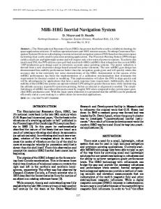
2. System model The inertial navigation system consists of three main parts: an analogue sensor with additional error correction, a digital coordinate transformation with supporting point inclusion and a PC-based software part. Figure1 gives an overview of the system structure. The sensor measures the analogue values sent from the "environment" and converts them to digital values. Communication between analogue and digital part is described using a high abstraction level. So the decision whether to use serial or parallel data transmission can be made using comparison simulations. In the digital part acceleration and rotation values are converted into position values and corrected by information from other signal sources (camera, map, etc.). The interface between the digital components and the PC is also described using high abstraction level. The decision whether to implement RS232 or USB for communication will be made after the examination of the necessary data rate. The PC
USB or RS232
Interface
digital error correction, coordinate transformation, supporting point inclusion
Interface
RS232 or 16 bit parallel
Interface
sensor for acceleration & rotation, analog error correction, A/D conversion
Interface
environment
accelerations, rotations, temperature
operating system, driver
applications (software)
PC
analogue subsystem supporting point information (camera, map) digital subsystem
Figure 1: System overview is used to plot the sensor’s position and to generate configuration data (cfg) for the digital and the analogue part. The system parts are explained in the following sections.
2.1. Analogue part
MAM-IF
3 x analog error correction for acceleration
MAM-IF
MAM-IF
MAM-IF
acceleration (x, y, z direction)
3 x A/D conversion for cfg acceleration
MAM-IF
3 x analog error correction for rotation
MAM-IF
MAM-IF
pitch, yaw)
MAM-IF
rot
MAM-IF
temperature
3 x A/D conversion for rotation
Interface analogue/digital subsystem
environment
acc
MAM-IF
The analogue subsystem consists of six sensors (three for acceleration and three for rotation detection), analogue error correction for each value and analogue to digital conversion. Figure 2 shows the structure of the subsystem. Module A MAM out sdf_outport
sdf
Module B MAM in sdf
V
elec
elec
elec_port
Figure 3: Multi-Architecture Modeling in SystemC-AMS
Figure 2: Analogue subsystem
For allowing easy change of abstraction level all components are surrounded by so called MAM interfaces. The Multi-Architecture Modeling (MAM) [4] connects all subcomponents at the lowest abstraction level. SystemC-AMS provides electrical nets as lowest level, so all component ports are converted to electrical ports. Therefore, if one subcomponent is refined to the electrical level and the others remain on the SDF level, no change in the interface definition is necessary. Figure 3 illustrates the MAM interface for a connection of two components with different levels of abstraction. Two models are used for the capacitive acceleration sensors. The simple model only considers a scaling factor and the sensor’s lowpass characteristic. This model is very fast and was used for a first estimation of system behaviour. The more detailed model is derived from a VHDL-AMS model which bases on geometry data [2]. This more accurate model is currently used for the development of the capacityvoltage transformation and a PWM circuit. This circuit should keep the sensor in the linear region around the operating point by applying reset voltages to the capacities.
acc digital
cfg
temperature & drift
coordinate transformation (quaternions)
pos
cfg
error correction (planned: Kalman filtering)
data
cfg
camera, step counter
map information
Figure 4: Digital subsystem
cfg
Interface digital/PC subsystem
Further signal processing takes place in the digital part. This component consists of three main modules and two supporting units as shown in figure 4. Four XILINX VirtexE 600 FPGAs are planned to carry this functionality.
digital subsystem
2.2. Digital part
The coordinate transformation from the sensor system to the environment system is implemented using quaternion rotation [5]. Quaternions are complex numbers with 3 imaginary parts. A 3D coordinate transformation can be done using adders and multipliers. Offset correction will be done using a camera and a step counter. The final error correction is planned to be realised in terms of a Kalman filter supported by additional position information generated by a map.
2.3. Connections
Abstraction Level
Two main connections have to be defined in this system: from the analogue part to the digital FPGAboards and from the FPGA-boards to the PC. The analogue-to-digital interface can be realised using serial (RS232) or 16bit-parallel communication depending on the effective speed of A/D-conversion and FPGA-application. Two realisations are possible for the interface from the digital part to the PC: a low speed serial communication (RS232) or a high speed solution (USB). RS232 should be fast enough for uplink (FPGA to PC), but downlink speed might be too slow for sending real time configuration data, especially to change map information. Interface One advantage of system-level modeling is the Transaction Transaction easy comparability of protocols by fast exchange of T Level Level transaction algorithms. In this system model SVE [6] Message Message (a SystemC extension for channel and protocol abM1 M2 M3 M4 Level Level straction) is used to allow different module abstracRTL RTL tion levels of the transfer source/target and transfer protocol encapsulation. Figure 5 gives an overview Figure 5: Mixed multi-level communication on the methodology of SVE. Comparison simulamodeling in SVE [6] tions will help the designer to find the best transfer solution.
2.4. Software The software subsystem consists of two main parts: the operating system (OS) and the user applications. The user programs run as procedures scheduled by the OS. Several approaches exist for the implementation of operating systems, e.g. [7] and [8]. Only a simple and abstract OS model is necessary for this inertial navigation system. The referenced models are more detailed so a small own OS model is implemented. It only communicates with one port (the interface to the FPGA boards) and has no interrupt handling. Data exchange between user programs is done by activation signals. In further system development this model will be refined to allow more realistic interprocess communication. Recently only two user applications are implemented: One target application saves the received position data to a file in MATLAB-format to allow graphical display of the resulting path. The other application generates configuration information for the digital and the analogue subsystem.
3. Simulation results For simulation an environment model is added to the sensor input. An application stores the received position data to a file in MATLAB format. A "go-and-come-back" drive is done as a first test example. The sensor is accelerated in one direction, turns around by 180˚ and returns to the origin. The simulation shows a final displacement to origin of 0.02% (3mm for a 20m way). After that a second test "triangle drive" is performed: Figure 7 shows the graphic representation of the system output in environment coordinates (x, y) responding to the stimuli in fig. 6 which are given in sensor coordinates. Reset position is (x = 0, y = 1m). Then the sensor is accelerated and slowed down by 1 m/s2 for every second. Now a 90˚ rightward rotation occurs, followed by a new acceleration/slow down process. The sensor is rotated rightwards by 135˚ and accelerates. The simulation results proof the
y [m]
1 [m/s²]
0
1
2
3
4
5
6
7
-1
1
8 time [s]
0.8 0.6
Pi/2 [rad/s]
0
0.4 1
2
3
4
5
6
7
8 time [s]
0.2 0
Figure 6: Stimuli for a triangle drive
0.2
0.4
0.6
0.8
1.0
x [m]
Figure 7: Simulation output of a triangle drive
quaternion transformation and the choosen data accuracy, but also show the necessity of additional supporting point information especially for gravitation correction. The simulation consumed a calculation time of 130s for simulating 8.1s real time (step width 100µs).
4. Conclusion and outlook In this paper a system model of an inertial navigation system has been presented. It consists of three subsystems: analogue, digital and software. SystemC-AMS offers the opportunity to simulate all subsystems together in one tool with different levels of abstraction. Multi-Architecture Modeling is used for easy exchange of components of different levels. Connections between the subsystems are realised by SVE, a SystemC extension for channel and protocol abstraction. First high-level simulations confirm the system concept. The focus of future work lies on testing alternative processing algorithms and component refinement. It is planned to integrate an opportunity of cost modeling for fast comparability of different realisations.
5. Acknowledgments The work presented here has been done within the project A2 "System Design" in cooperation with project A1 "Component Development" of the SFB 379 (collaborative research center), which is funded by the German Science Foundation (DFG). The used version of SystemC-AMS was kindly supplied by Karsten Einwich, Fraunhofer Gesellschaft EAS/IIS Dresden, Germany. References [1] Billep, D.; Dienel, M.: Patent Application DE 102004046411.1 Beschleunigungssensor. [2] Markert, E.; Schlegel, M.; Dienel, M.; Herrmann, G.; Müller, D.: Modeling of a new acceleration sensor as part of a 2D sensor array in VHDL-AMS. Nanotech 2005, Anaheim CA; May 2005. [3] Einwich, K. et. al.: White Paper SystemC-AMS Study Group. http://www.systemc-ams.org [4] Schlegel, M.; Herrmann, G.; Müller, D.: Application of the ’Multi Architecture Modelling’ design method to system level MEMS simulation. DTIP 2003, Mandelieu - La Napoule; 5-7 May 2003. [5] Hart, J. C.; Francis, G. K.; Kauffman, L. H.: Visualizing Quaternion Rotation. ACM Transactions on Graphics, Vol.13, No. 3, Pages 256-276; July 1994. [6] Siegmund, R.; Müller, D.: SystemCSV-Extension of SystemC for Mixed Multi-Level Communication Modeling and Interface-based System Design. DATE 2001, Munich; March 2001. [7] Bouchhima, A; Yoo, S.; Jerraya, A. A.: Fast and accurate timed execution of high level embedded software using HW/SW interface simulation model. ASP-DAC 2004. [8] Gerstlauer, A.; Yu, H.; Gaijski, D.: RTOS Modeling for System Level Design. DATE 2003, Munich; 3-7 March 2003.