iLink level acks (negative acks, dupacks, â¦) iOther mechanisms (e.g., Snoop, as discussed later) g How much time is required for a link layer retransmission?
TCP in Wireless and Mobile Networks Challenges and Solutions
Jaydip Sen Innovation Labs, Tata Consultancy Services Ltd. India 1
Agenda g
Wireless link characteristics
g
TCP/IP over wireless
g
A quick review of TCP
iCumulative ACKs iDelayed ACKs iWindow-based flow control / congestion control g
A case study with 802.11 multi-hop network
g
Schemes to improve TCP performance in wireless networks
2
Wireless Link Characteristics g
Transmission errors
g
Low bandwidth
g
Long or variable latency
g
Asymmetry in bandwidth and error characteristics
3
TCP/IP over Wireless g
De facto standard for internetworking
g
Allows wireless devices to connect seamlessly to the Internet
g
TCP over wireless introduces some problems not faced in wired networks (transmission errors, mobility etc.)
4
Quick Review of TCP/IP
5
Internet Protocol (IP)
g
Packets may be delivered out-of-order
g
Packets may be lost
g
Packets may be duplicated
6
Transmission Control Protocol (TCP)
g
Guarantees reliable ordered delivery of packets
g
Implements congestion control
g
Reliability is achieved by means of retransmissions, if necessary
g
End-to-end semantics iACKs sent to TCP sender confirm delivery of data received by TCP receiver iACK for data sent only after data has reached receiver
7
Cumulative Acknowledgments g
A new cumulative Acknowledgment is generated only on receipt of a new in-sequence packet 40
39 33
38 34
41
35
40 34
39 35
i
37
data
38 36
i
36
ack
37
8
Delayed Acknowledgments g
g
An ACK is delayed until ianother packet is received, or idelayed ack timer expires (200 ms typical) New ack not produced Reduces ACK traffic on receipt of packet 36, but on receipt of 37
40
39
38
33
41
37 35
40
39 35
38 37 9
Duplicate Acknowledgments g
A dupack is generated whenever an out-of-order segment arrives at the receiver 40
39
38
37
34
42
41
36
40 36
(Above example assumes delayed acks)
39 36
Dupack On receipt of 38
10
Duplicate Acknowledgments g g
Duplicate ACKs are not delayed Duplicate ACKs may be generated when ia packet is lost, or ia packet is delivered out-of-order (OOO) 40
39
37
38
34
41
40
36
39
37 36
36
Dupack On receipt of 38
11
Number of dupacks depends on how much OOO a packet is 40
39
37
38
34
36
New Ack 41
40
New Ack 39
34
36
New Ack 42
37
New Ack 41
40 36
New Ack
36
Dupack 39
36
Dupack
38
New Ack
12
Window-Based Flow Control g g
Sliding window protocol Window size minimum of ireceiver’s advertised window - determined by available buffer space at the receiver icongestion window - determined by the sender, based on feedback from the network
Sender’s window 1 2 3 4 5 6 7 8 9 10 11 12 13 ACKs received
Not transmitted 13
Window-Based Flow Control
Sender’s window 1 2 3 4 5 6 7 8 9 10 11 12 13
ACK 5
1 2 3 4 5 6 7 8 9 10 11 12 13
Sender’s window
14
Window-Based Flow Control g
Congestion window size bounds the amount of data that can be sent in a round-trip time
g
Throughput delay * bandwidth ? iQueuing at intermediate routers
• increased RTT due to queuing delays
iPotential packet loss
16
How does TCP detect a packet loss?
g
Retransmission Time-Out (RTO)
g
Duplicate Acknowledgments
17
Detecting Packet Loss Using Retransmission Timeout (RTO) g
At any time, TCP sender sets retransmission timer for only one packet
g
If ACK for the timed packet is not received before timer goes off, the packet is assumed to be lost
g
RTO is dynamically calculated
18
Retransmission Timeout (RTO) Calculation
g
RTO = Mean + 4 * Mean Deviation iStandard deviation σ : σ 2 = average of (sample – mean)2 iMean deviation δ = average of |sample – mean| iMean deviation easier to calculate than standard deviation iMean deviation is more sensitive: δ >= σ
g
A large variation in the RTT increases the deviation, leading to a larger RTO
19
Timeout Granularity g
RTT is measured as a discrete variable, in multiples of a “tick”
g
1 tick = 500 ms is usually used
g
Smaller tick sizes may also be used (e.g., in Solaris)
g
RTO is at least 2 clock ticks
20
Exponential Backoff g
Double RTO on each timeout
T1
T2 = 2 * T1 Timeout interval doubled
Packet transmitted Time-out occurs before ACK is received, packet retransmitted
21
Fast Retransmission
g
Timeouts can take too long ihow to initiate retransmission sooner?
g
Fast retransmit
22
Detecting Packet Loss Using Dupacks Fast Retransmit Mechanism g
Dupacks may be generated due to ipacket loss, or iout-of-order packet delivery
g
TCP sender assumes that a packet loss has occurred if it receives three dupacks consecutively 12 8 11 10 9 7
3 dupacks are also generated if a packet is delivered at least 3 places beyond its in-sequence location
Fast retransmit useful only if lower layers deliver packets “almost ordered” fashion ---- otherwise, unnecessary fast retransmit 23
Congestion Avoidance and Control Slow Start g Initially, congestion window size cwnd = 1 MSS (maximum segment size) g Increments window size by 1 MSS on each new ack g Slow start phase ends when window size reaches the slow-start threshold g
cwnd grows exponentially with time during slow start ifactor of 1.5 per RTT if every other packet is ack’d ifactor of 2 per RTT if every packet is ack’d iCould be less if sender does not always have data to send 24
Congestion Avoidance
g
On each new ack, increase cwnd by 1/cwnd packets
g
cwnd increases linearly with time during congestion avoidance i1/2 MSS per RTT if every other packet ack’d i1 MSS per RTT if every packet ack’d
25
C o n g estio n W in d o w size (seg m ents)
14
Congestion avoidance
12 10 8
Slow start threshold
6
Slow start
4 2 0 0
1
2
3
4
5
6
7
8
Time (round trips)
Example assumes that acks are not delayed
26
Congestion Control g
On detecting a packet loss, TCP sender assumes that network congestion has occurred
g
On detecting packet loss, TCP sender drastically reduces the congestion window size
g
Reducing congestion window reduces amount of data that can be sent per RTT ithroughput decreases
27
Congestion Control -- Timeout g
On a timeout, the congestion window is reduced to the initial value of 1 MSS
g
The slow start threshold is set to half the window size before packet loss imore precisely, ssthresh = maximum of min(cwnd,receiver’s advertised window)/2 and 2 MSS
g
Slow start is initiated
28
After timeout
25 cwnd = 20
20 15 10
ssthresh = 10
ssthresh = 8
5
25
22
20
15
12
9
6
3
0 0
Congestion window (segments)
Congestion Control - Timeout
Time (round trips) 29
Congestion Control - Fast retransmit g
Fast retransmit occurs when multiple (>= 3) dupacks come back
g
Fast recovery follows fast retransmit
g
Different from timeout : slow start follows timeout itimeout occurs when no more packets are getting across ifast retransmit occurs when a packet is lost, but latter packets get through iack clock is still there when fast retransmit occurs ino need to slow start 30
Fast Recovery g
ssthresh = min (cwnd, receiver’s advertised window)/2 (at least 2 MSS)
g
Retransmits the missing segment (fast retransmit)
g
cwnd = ssthresh + number of dupacks
g
When a new ack comes: cwnd = ssthreh iEnter into congestion avoidance phase
31
W indo w size (se g m e nts)
After fast recovery
10
Receiver’s advertized window
8 6 4 2 0 0
2
4
6
8
10 12 14
Time (round trips)
After fast retransmit and fast recovery window size is reduced in half.
32
TCP Reno g g g g
Slow-start Congestion avoidance Fast retransmit Fast recovery
33
A Case Study IEEE 802.11 in Multi-hop Wireless Network
Author: Shugong Xu, Tarek Saadawi City University of New York
34
The Work g
This work is about TCP over multi-hop networks
g
Conclusion: Interactions between 802.11 MAC, routing and TCP layers can be destructive
g
Experimental Scenario
iA Static String Topology iTCP as Transport Layer Protocol 0 g
1
2
3
4
5
6
7
Problems
iInstability Problem iUnfairness Problem 35
Simulation Environment g g g g
Simulator: ns-2 with wireless extensions MAC Layer: IEEE 802.11 MAC Distributed Coordination function(DCF). Transport Layer: TCP connections carrying bulk transfers (always have data) Network Scenario
iA Static String Network Topology iInterference range is a little more than two times the communication range
Interference Range
0
Communication Range
1
2
3
4
5
6
7
36
Instability Problem
1 Source
2
3
4
5 Destination
g
A single TCP connection, with node 1 as the source and node 5 as the destination.
g
Three sets of experiments conducted with Maximum Window Size(window_) 32, 8, and 4 respectively.
37
Instability Problem g
When window_= 32 or 8, serious oscillation in throughput observed
g
When window_4, throughput is stable
38
Instability Problem—Trace Analysis(1)
Interference Range of Node 2 RTS
1
Data
2 CTS
3
4
5 Ack
39
Instability Problem—Summary g
Collision and exposed terminal problem prevent node 2 from receiving RTS from or sending CTS to node 1.
g
The random back-off, big data packet, and sending back-to-back packets worsen the above problems.
g
When window_ = 4, the chance to send back a CTS is greatly increased, so the throughput becomes stable.
g
After node 1 fails seven times to receive CTS, node 1 believes there is a route failure and starts a route discovery.
g
Before a route is available, node 1 cannot send out a data packet. This period usually is long enough to cause a timeout at the TCP sender.
g
For TCP, timeout triggers Slow Start, which significantly reduces the throughput.
40
Unfairness Problem
Second Session
2 Source
g g
3
First Session
4
Destination
5
6 Source
In the first session, data flow from 6 to 4. In the second session, data flow from 2 to 3. The first session starts at 10.0s. The second session starts at 30.0s.
41
Unfairness Problem g g
The first session has a throughput of about 450kbps from 10s to 30s, and 0kbps after 30s. The second session has a throughput of about 900kbps from 30s to 130s.
42
Unfairness Problem g
The first session never succeeds to send out packet with sequence number 2164.
43
Unfairness Problem —Trace Analysis Interfering Range of Node 5 Data
2
RTS
3 Ack
4
Data
5 CTS
6 No Route
Interfering Range of Node 4
44
Unfairness Problem —Trace Analysis Interfering Range of Node 5 Data
2
RTS
3 Ack
4
Data
5 CTS
6 No Route
Interfering Range of Node 4
45
Unfairness Problem—Summary g
In one-hop TCP connections, the interval between packet transmission is larger than that of the multihop TCP connections, which gives the one-hop connection more chances to transmit data.
g
Random back-off is actually advantageous to the last succeeding host.
g
This problem is called “One-hop unfairness problem”
iAuthors argue that since one-hop connection is common in a wireless network this problem must be addressed
46
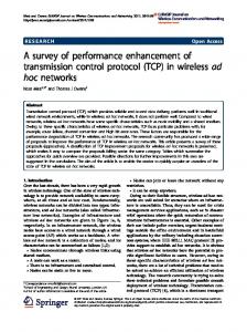
Impact of transmission errors on TCP performance
47
Random Errors g
If number of errors is small, they may be corrected by an error correcting code
g
Excessive bit errors result in a packet being discarded, possibly before it reaches the transport layer
48
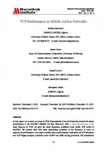
Random Errors May Cause Fast Retransmit
40
39
38
37
34
36
Example assumes delayed ack - every other packet ack’d 49
Random Errors May Cause Fast Retransmit
41
40 34
39
38 36
Example assumes delayed ack - every other packet ack’d 50
Random Errors May Cause Fast Retransmit
42
41
40 36
39 36
dupack Duplicate acks are not delayed 51
Random Errors May Cause Fast Retransmit
43
42 36
41
40 36
36
Duplicate acks
52
Random Errors May Cause Fast Retransmit
44
43
42 36
41 36
36
3 duplicate acks trigger fast retransmit at sender
53
Random Errors May Cause Fast Retransmit g
Fast retransmit results in iretransmission of lost packet ireduction in congestion window
g
Reducing congestion window in response to errors is unnecessary
g
Reduction in congestion window reduces the throughput
54
Sometimes Congestion Response May be Appropriate in Response to Errors g
On a CDMA channel, errors occur due to interference from other user, and due to noise [Karn99pilc] iInterference due to other users is an indication of congestion. If such interference causes transmission errors, it is appropriate to reduce congestion window iIf noise causes errors, it is not appropriate to reduce window
g
When a channel is in a bad state for a long duration, it might be better to let TCP backoff, so that it does not unnecessarily attempt retransmissions while the channel remains in the bad state [Padmanabhan99pilc] 55
Burst Errors May Cause Timeouts g
g g
g
g
If wireless link remains unavailable for an extended duration, a window worth of data may be lost idriving through a tunnel Timeout results in slow start Slow start reduces congestion window to 1 MSS, reducing throughput Reduction in window in response to errors unnecessary Multiple random packet losses can also result in a timeout when using TCP-Reno (and to a lesser extent when using SACK) 56
Impact of Transmission Errors g
TCP cannot distinguish between packet losses due to congestion and transmission errors
g
Unnecessarily reduces congestion window
g
Throughput suffers
57
Classification of Schemes to Improve Performance of TCP in Wireless Networks
58
Techniques to Improve TCP Performance in Wireless Networks Classification 1 Classification based on nature of actions taken to improve performance g
Hide the losses from the sender iif sender is unaware of the packet loss, it will not reduce congestion window
g
Let the sender know, or determine the cause of packet loss iif sender knows that a packet loss is due to errors, it will not reduce congestion window
59
Techniques to Improve TCP Performance in Wireless Networks Classification 2 Classification based on where modifications are done g
At the sender node only
g
At the receiver node only
g
At intermediate node(s) only
g
Combinations of the above 60
Ideal Behavior g
Ideal TCP behavior: Ideally, the TCP sender should simply retransmit a packet lost due to transmission errors, without taking any congestion control actions
iSuch a TCP is referred to as Ideal TCP iIdeal TCP is typically not realizable g
Ideal network behavior: Transmission errors should be hidden from the sender -- the errors should be recovered transparently and efficiently
g
Proposed schemes attempt to approximate one of the above two ideals
61
Selected Schemes to Improve Performance of TCP in Wireless Networks
62
Various Schemes g g g g g g
Link layer mechanisms Split connection approach TCP-aware link layer Explicit notification Receiver-based discrimination Sender-based discrimination
For a brief overview, see [Dawkins &Montenegro]
63
Link Layer Mechanisms
64
Link Layer Mechanisms Forward Error Correction g
Forward Error Correction (FEC) [Lin83] can be used to correct small number of errors
g
Correctable errors hidden from the TCP sender
g
FEC incurs overhead even when errors do not occur iAdaptive FEC schemes [Eckhardt98] can reduce the overhead by choosing appropriate FEC dynamically
65
Link Layer Mechanisms Link Level Retransmissions g
Link level retransmission schemes retransmit a packet at the link layer, if errors are detected
g
Retransmission overhead incurred only if errors occur iunlike FEC overhead
66
Link Layer Mechanisms In general g
Use FEC to correct a small number of errors
g
Use link level retransmission when FEC capability is exceeded
67
Link Level Retransmissions Link layer state
TCP connection application
application
application
transport
transport
transport
network
network
link
link
link
physical
physical
physical
rxmt
wireless
network
68
Link Level Retransmissions Issues g
How many times to retransmit at the link level before giving up? iFinite bound -- semi-reliable link layer iNo bound -- reliable link layer
g
What triggers link level retransmissions? iLink layer timeout mechanism iLink level acks (negative acks, dupacks, …) iOther mechanisms (e.g., Snoop, as discussed later)
g
How much time is required for a link layer retransmission? iSmall fraction of end-to-end TCP RTT iLarge fraction of end-to-end TCP RTT iInteraction of timers at link level and TCP?
69
Link Level Retransmissions Issues g
Should the link layer deliver packets as they arrive, or deliver them in-order? iLink layer may need to buffer packets and reorder if necessary so as to deliver packets in-order
70
Link Level Retransmissions Issues g
Retransmissions can cause head-of-the-line blocking Receiver 1
Base station g g
Receiver 2
Although link to receiver 1 may be in a bad state, the link to receiver 2 may be in a good state Retransmissions to receiver 1 can possibly block a packet from being sent to receiver 2
71
Link Level Retransmissions (Early Studies) g
The sender’s Retransmission Timeout (RTO) is a function of measured RTT (round-trip times) iLink level retransmits increase RTT, therefore, RTO
g
If errors are not frequent, frequent RTO will not account for RTT variations due to link level retransmissions iWhen errors occur, the sender may timeout & retransmit before link level retransmission is successful iSender and link layer both retransmit iDuplicate retransmissions (interference) waste wireless bandwidth iTimeouts also result in reduced congestion window
72
Link Level Retransmissions A More Accurate Picture g
With large RTO, interference is unlikely, if time required for link-level retransmission is small compared to TCP RTO [Balakrishnan96Sigcomm] iStandard TCP RTO is often large iMinimum RTO is large enough to allow a small number of link level retransmissions, if link level RTT is relatively small iInterference due to timeout not a significant issue when wireless RTT is small, and RTO is large [Eckhardt98]
73
Link Level Retransmissions A More Accurate Picture g
Frequent errors increase RTO significantly on slow wireless links iRTT on slow links is large, retransmissions result in large variance, pushing RTO up iLikelihood of interference between link layer and TCP retransmissions is smaller iBut congestion response will be delayed due to larger RTO iWhen wireless losses do cause timeout, much time is wasted
74
Large TCP Retransmission Timeout Intervals
g
Good for reducing interference with link level retransmits
g
Bad for recovery from congestion losses
g
A timeout mechanism is needed that responds appropriately for both types of losses iAn open problem
75
Link Level Retransmissions g
Selective repeat protocols can deliver packets out of order
g
Significantly out-of-order delivery can trigger TCP to fast retransmit iRedundant retransmission from TCP sender iReduction in congestion window
g
Example: Receipt of packets 3,4,5 triggers dupacks
6
2
5
Lost packet Retransmitted packet
4
3
2
1
76
Link Level Retransmissions In-order delivery g
To avoid unnecessary fast retransmit, link layer using retransmission should attempt to deliver packets “almost in-order”
6
5
4
3
2
2
1
6
5
2
4
3
2
1 77
Adaptive Link Layer Strategies [Lettieri98,Eckhardt98,Zorzi97] Adaptive protocols attempt to dynamically choose: g
FEC code
g
Retransmission limit
g
Frame size
78
Link Layer Schemes: Summary When is a reliable link layer beneficial to TCP performance? g
if it provides almost in-order delivery
and g
TCP retransmission timeout large enough to tolerate additional delays due to link level retransmits
79
Link Layer Schemes: Classification
g
Hides wireless losses from TCP sender
g
Link layer modifications needed at both ends of wireless link iTCP need not be modified
80
Various Schemes g g g g g g
Link layer mechanisms Split connection approach TCP-aware link layer Explicit notification Receiver-based discrimination Sender-based discrimination
81
Split Connection Approach
82
Split Connection Approach g
End-to-end TCP connection is broken into one connection on the wired part of route and one over wireless part of the route
g
A single TCP connection split into two TCP connections iif wireless link is not last on route, then more than two TCP connections may be needed
83
Split Connection Approach
g
Connection between wireless host MH and fixed host FH goes through base station BS
g
FH-MH = FH-BS
FH Fixed Host
+
BS Base Station
BS-MH
MH Mobile Host
84
Split Connection Approach
g
Split connection results in independent flow control for the two parts
g
Flow/error control protocols, packet size, time-outs, may be different for each part
FH Fixed Host
BS Base Station
MH Mobile Host
85
Split Connection Approach Per-TCP connection state TCP connection
TCP connection application
application
transport
transport
transport
network
network
network
link
link
link
physical
physical
physical
rxmt
wireless
application
86
Split Connection Approach Indirect TCP [Bakre95,Bakre97] g g
FH - BS connection : Standard TCP BS - MH connection : Standard TCP
87
Split Connection Approach Selective Repeat Protocol (SRP) [Yavatkar94] g g
g
FH - BS connection : Standard TCP BS - MH connection : Selective Repeat Protocol on top of UDP Performance better than Indirect-TCP (I-TCP), because wireless portion of the connection can be tuned to wireless behavior
88
Split Connection Approach : Other Variations g
Asymmetric transport protocol (Mobile-TCP) [Haas97icc] Low overhead protocol at wireless hosts, and higher overhead protocol at wired hosts ismaller headers used on wireless hop (header compression) isimpler flow control - on/off for MH to BS transfer iMH only does error detection, BS does error correction too iNo congestion control over wireless hop
89
Split Connection Approach : Classification
g g g
Hides transmission errors from sender Primary responsibility is with the base station If specialized transport protocol is used on wireless, then wireless host also needs modification
90
Split Connection Approach : Advantages g
BS-MH connection can be optimized independent of FH-BS connection
iDifferent flow / error control on the two connections g
Local recovery of errors
iFaster recovery due to relatively shorter RTT on wireless link g
Good performance achievable using appropriate BS-MH protocol
iStandard TCP on BS-MH performs poorly when multiple packet losses occur per window (timeouts can occur on the BS-MH connection) iSelective ACKs improve performance in such cases
91
Split Connection Approach : Disadvantages g
End-to-end semantics violated iAck may be delivered to sender, before data is delivered to the receiver iMay not be a problem for applications that do not rely on TCP for the end-to-end semantics
39 40 38 FH
37
BS 40
MH 36 92
Split Connection Approach : Disadvantages g
BS retains hard state BS failure can result in loss of data (unreliability) iIf BS fails, packet 40 will be lost iBecause it is ack’d to sender, the sender does not buffer 40 any further
39 40 38 FH
37
BS 40
MH 36 93
Split Connection Approach : Disadvantages g
BS retains hard state Hand-off latency increases due to state transfer iData that has been ack’d to sender, must be moved to new base station 39 40 BS
FH
38
37 MH 36
40
39 40
New base station
MH
Hand-off
94
Split Connection Approach : Disadvantages
g
Buffer space needed at BS for each TCP connection iBS buffers tend to get full, when wireless link is slow (one window worth of data on wired connection could be stored at the base station, for each split connection)
g
Window on BS-MH connection reduced in response to errors imay not be an issue for wireless links with small delaybandwidth product
95
Split Connection Approach : Disadvantages
g
Extra copying of data at BS icopying from FH-BS socket buffer to BS-MH socket buffer iincreases end-to-end latency
g
May not be useful if data and acks traverse different paths (both do not go through the base station) iExample: data on a satellite wireless hop, acks on a dial-up channel
data
BS
FH
MH
ack
96
Various Schemes g g g g g g
Link layer mechanisms Split connection approach TCP-aware Link Layer Explicit notification Receiver-based discrimination Sender-based discrimination
97
TCP-Aware Link Layer
98
Snoop Protocol [Balakrishnan95acm]
g
Retains local recovery of Split Connection approach and link level retransmission schemes
g
Improves on split connection iend-to-end semantics retained isoft state at base station, instead of hard state
99
Snoop Protocol Per TCP-connection state TCP connection application
application
application
transport
transport
transport
network
network
link
link
link
physical
physical
physical
FH
BS
rxmt
wireless
network
MH 100
Snoop Protocol g
g
g
Buffers data packets at the base station BS ito allow link layer retransmission When dupacks received by BS from MH, retransmit on wireless link, if packet present in buffer Prevents fast retransmit at TCP sender FH by dropping the dupacks at BS
FH
BS
MH
101
Snoop : Example 35 36
TCP state maintained at link layer
37 38 40
39
38
FH
37
BS 34
MH 36
Example assumes delayed ack - every other packet ack’d 102
Snoop : Example 35
39
36 37 38 41
40 34
39
38 36
103
Snoop : Example 37
40
38 39 42
41
40 36
39 36
dupack Duplicate acks are not delayed 104
Snoop : Example 37
40
38
41
39 43
42 36
41
40 36
36
Duplicate acks
105
Snoop : Example
44
37
40
38
41
39
42
43
FH
37
41
BS
MH 36
36
Discard dupack Dupack triggers retransmission 36 of packet 37 from base station BS needs to be TCP-aware to be able to interpret TCP headers
106
Snoop : Example
45
37
40
38
41
39
42
44
43
42
37 36
36
36 36 107
Snoop : Example
46
37
40
43
38
41
44
39
42
45
43
42 36
TCP sender does not fast retransmit
41
36 36 36 108
Snoop : Example
47
37
40
43
38
41
44
39
42
45
46
44
43 41
TCP sender does not fast retransmit
36 36 36 36 109
Snoop : Example 42
45
43
46
44
48
47
45
FH
44
BS 41
MH 43
36 36 36 36 110
Snoop Protocol When Beneficial? g
Snoop prevents fast retransmit from sender despite transmission errors, and out-of-order delivery on the wireless link
111
Snoop Protocol : Classification
g
Hides wireless losses from the sender
g
Requires modification only in BS (network-centric approach)
112
Snoop Protocol : Advantages g
High throughput can be achieved
iperformance further improved by using selective acks g
Local recovery from wireless losses
g
Fast retransmit not triggered at sender despite out-of-order link layer delivery
g
End-to-end semantics retained
g
Soft state at base station
iloss of the soft state affects performance, but not correctness
113
Snoop Protocol : Disadvantages
g
Link layer at BS needs to be TCP-aware
g
Not feasible if TCP headers are encrypted (IPsec)
g
Cannot be used if TCP data and TCP acks traverse different paths (both do not go through the base station)
114
WTCP Protocol [Ratnam98] g g
g
Snoop hides wireless losses to the sender But sender’s RTT estimates may be larger in presence of errors Larger RTO results in slower response for congestion losses
FH
BS
MH
115
WTCP Protocol g g
g
g
WTCP performs local recovery, similar to Snoop In addition, WTCP uses the timestamp option to estimate RTT The base station adds base station residence time to the timestamp when processing an ack received from the wireless host Sender’s RTT estimate not affected by retransmissions on wireless link
FH
BS
MH
116
WTCP Example
3
3
FH
BS 4
MH 3
Numbers in this figure are timestamps Base station residence time is 1 unit 117
WTCP : Disadvantages g g
g
Requires use of the timestamp option May be useful only if retransmission times are large ilink stays in bad state for a long time ilink frequently enters a bad state ilink delay large WTCP does not account for congestion on wireless hop iassumes that all delay at base station is due to queuing and retransmissions iwill not work for shared wireless LAN, where delays also incurred due to contention with other transmitters 118
Various Schemes g g g g g g
Link-layer retransmissions Split connection approach TCP-aware link layer Explicit notification Receiver-based discrimination Sender-based discrimination
119
Explicit Notification
120
Explicit Notification Schemes General Philosophy g
Approximate Ideal TCP behavior: Ideally, the TCP sender should simply retransmit a packet lost due to transmission errors, without taking any congestion control actions
g
A wireless node somehow determines that packets are lost due to errors and informs the sender using an explicit notification
g
Sender, on receiving the notification, does not reduce congestion window, but retransmits lost packet 121
Explicit Notification Schemes
g
Motivated by the Explicit Congestion Notification (ECN) proposals [Floyd94]
Variations proposed in literature differ in g g g
who sends explicit notification how they know when to send the explicit notification what the sender does on receiving the notification 122
Explicit Notification Space Communication Protocol StandardsTransport Protocol (SCPS-TP) Satellite wireless
Ground station
TCP destinations
123
Space Communication Protocol StandardsTransport Protocol (SCPS-TP) g
g
The receiving ground station keeps track of how many packets with errors are received (their checksums failed) When the error rate exceeds a threshold, the ground station sends corruption experienced messages to destinations of recent error-free TCP packets
idestinations are cached g g
The TCP destinations tag acks with corruption-experienced bit TCP sender, after receiving an ack with corruption-experienced bit, does not back off until it receives an ack without that bit (even if timeout or fast retransmit occurs)
124
Explicit Loss Notification [Balakrishnan98] when MH is the TCP sender g g
g
g
Wireless link first on the path from sender to receiver The base station keeps track of holes in the packet sequence received from the sender When a dupack is received from the receiver, the base station compares the dupack sequence number with the recorded holes iif there is a match, an ELN bit is set in the dupack When sender receives dupack with ELN set, it retransmits packet, but does not reduce congestion window Record MH
4
3
wireless
hole at 2 2 1 BS 1 1
4
3
1
1 1 Dupack with ELN set
FH 125
Explicit Bad State Notification [Bakshi97] when MH is TCP receiver g
Base station attempts to deliver packets to the MH using a link layer retransmission scheme
g
If packet cannot be delivered using a small number of retransmissions, BS sends an Explicit Bad State Notification (EBSN) message to TCP sender
g
When TCP sender receives EBSN, it resets its timer itimeout delayed, when wireless channel in bad state 126
Partial Ack Protocols [Cobb95][Biaz97] g g
g
Send two types of acknowledgments A partial acknowledgment informs the sender that a packet was received by an intermediate host (typically, base station) Normal TCP cumulative ack needed by the sender for reliability purposes
127
Partial Ack Protocols g
When a packet for which a partial ack is received is detected to be lost, the sender does not reduce its congestion window iloss assumed to be due to wireless errors 37
37
Partial ack
36
Cumulative ack
128
Variations g
g
Base station may or may not locally buffer and retransmit lost packets Partial ack for all packets or a subset ? 37
37
Partial ack
36
Cumulative ack
129
Explicit Loss Notification [Biaz99thesis] when MH is TCP receiver g
Attempts to approximate hypothetical ELN proposed in [Balakrishnan96] for the case when MH is receiver
g
Caches TCP sequence numbers at base station, similar to Snoop. But does not cache data packets, unlike Snoop.
g
Duplicate acks are tagged with ELN bit before being forwarded to sender if sequence number for the lost packet is cached at the base station
g
Sender takes appropriate action on receiving ELN 130
Explicit Loss Notification [Biaz99thesis] when MH is TCP receiver Sequence numbers cached at base station
39 38 37
39 36
37
38
37
37
Dupack with ELN
131
Various Schemes g g g g g g g
Link-layer retransmissions Split connection approach TCP-Aware link layer TCP-Unaware approximation of TCP-aware link layer Explicit notification Receiver-based discrimination Sender-based discrimination
132
Receiver-Based Discrimination Scheme
133
Receiver-Based Scheme [Biaz98Asset]
g g
g
g
MH is TCP receiver Receiver uses a heuristic to guess cause of packet loss When receiver believes that packet loss is due to errors, it sends a notification to the TCP sender TCP sender, on receiving the notification, retransmits the lost packet, but does not reduce congestion window
134
Receiver-Based Scheme g
Packet loss due to congestion 12 FH
11
10 BS
MH
T 12 FH
BS
11 Congestion loss
10 MH
135
Receiver-Based Scheme g
Packet loss due to transmission error 12 FH
11
10 BS
MH
2T 12 FH
BS
11 Error loss
10 MH
136
Receiver-Based Scheme
g
Receiver uses the inter-arrival time between consecutively received packets to guess the cause of a packet loss
g
On determining a packet loss as being due to errors, the receiver may itag corresponding dupacks with an ELN bit, or isend an explicit notification to sender
137
Receiver-Based Scheme Diagnostic Accuracy [Biaz99Asset]
Congestion losses
Error losses 138
Receiver-Based Scheme : Disadvantages g
Limited applicability
g
The slowest link on the path must be the last wireless hop ito ensure some queuing will occur at the base station
g
The queuing delays for all packets (at the base station) should be somewhat uniform imultiple connections on the link will make inter-packet delays variable
139
Receiver-Based Scheme : Advantages
g
Can be implemented without modifying the base station (an “end-to-end” scheme)
g
May be used despite encryption, or if data & acks traverse different paths
140
Various Schemes g g g g g g g
Link-layer retransmissions Split connection approach TCP-Aware link layer TCP-Unaware approximation of TCP-aware link layer Explicit notification Receiver-based discrimination Sender-based discrimination
141
Sender-Based Discrimination Scheme
142
Sender-Based Discrimination Scheme [Biaz98ic3n,Biaz99techrep] g
Sender can attempt to determine cause of a packet loss
g
If packet loss is determined to be due to errors, sender does not reduce congestion window
g
Sender can only use statistics based on round-trip times, window sizes, and loss pattern iunless network provides more information (example: explicit loss notification) 143
Heuristics for Congestion Avoidance
g
Define condition C as a function of congestion window size and observed RTTs
g
Condition C evaluated when a new RTT is calculated icondition C typically evaluates to 2 or 3 possible values ifor now assume 2 values: TRUE or FALSE
g
If (C == True) reduce congestion window
g
Several proposals for condition C 144
Heuristics for Congestion Avoidance Some proposals g
Normalized Delay Gradient [jain89] r = [RTT(i)-RTT(i-1)] / [RTT(i)+RTT(i-1)] w = [W(i)-W(i-1)] / [W(i)+W(i-1)]
Condition C = (r/w > 0)
145
Heuristics for Congestion Avoidance Some proposals g
Normalized Throughput Gradient [Wang91] Throughput gradient TG(i) = [T(i) - T(i-1) ] / [ W(i)-W(i-1)] Normalized Throughout Gradient NTG = TG(i) / TG(1) Condition C = (NTG < 0.5) 146
Heuristics for Congestion Avoidance Some proposals g
TCP Vegas [Brakmo94] expected throughput ET = W(i) / RTTmin actual throughput
AT = W(i) / RTT(i)
Condition C = ( ET - AT > beta) where beta is a predefined threshold value
147
Sender-Based Heuristics
g
Record latest value evaluated for condition C
g
When a packet loss is detected
iif current evaluation of C is TRUE, assume packet loss is due to congestion ielse assume that packet loss is due to transmission errors g
If packet loss determined to be due to errors, do not reduce congestion window 148
Sender-Based Heuristics : Disadvantage
g
Does not work quite well enough as yet !!
Reason g
Statistics collected by the sender is influenced by other traffic on the network
g
Not much correlation between observed short-term statistics, and onset of congestion 149
Sender-Based Heuristics : Advantages
g
Only sender needs to be modified
150
Why do Statistical Technique Perform Poorly?
g
The techniques we evaluated use simple statistics on RTT and window size W to draw conclusions about state of the network Unfortunately, correlation between RTT and W is often weak
Fraction of TCP connections
g
Coefficient of correlation (RTT,W)
151
Statistical Techniques Future Work g
Other statistical measures ?
g
Mechanisms that achieve good TCP throughput despite not-too-good diagnostic accuracy
152
TCP in Wireless Networks Conclusion g
g
g
Performance of standard TCP in wireless networks is very poor due to transmission errors and burst errors in communication because of bad wireless links Many techniques have been proposed, and several approaches perform well in many environments Recommendation: Prefer end-to-end techniques iEnd-to-end techniques are those which do not require TCP-specific help from lower layers iLower layers may help improve TCP performance without taking TCP-specific actions. Examples: Semi-reliable link level retransmission schemes Explicit notification
• •
153
Thank You
154