Sep 22, 2005 - Email: { kgl | marius | bnielsen | ask}@cs.aau.dk. ABSTRACT .... broadcast (one-to-many) synchronizations and other extensions. UP-.
Testing Real-Time Embedded Software using UPPAAL-TRON An Industrial Case Study Kim G. Larsen
Marius Mikucionis
Brian Nielsen
Arne Skou
Center of Embedded Software Systems, CISS Aalborg University Fredrik Bajersvej 7B, DK-9220 Aalborg, Denmark Email: { kgl | marius | bnielsen | ask}@cs.aau.dk
ABSTRACT U PPAAL -TRON is a new tool for model based online black-box conformance testing of real-time embedded systems specified as timed automata. In this paper we present our experiences in applying our tool and technique on an industrial case study. We conclude that the tool and technique is applicable to practical systems, and that it has promising error detection potential and execution performance.
Categories and Subject Descriptors D.2 [Software Engineering]: Miscellaneous; D.2.5 [Software Engineering]: Testing and Debugging—symbolic execution, monitors, testing tools
General Terms Algorithms, Experimentation, Languages, Theory, Verification
Keywords Black-box testing, online testing, embedded systems, control software, real-time systems
1.
INTRODUCTION
Model-based testing is a promising approach for improving the testing of embedded systems. Given an abstract formalized model (ideally developed as the design process) of the behaviour of aspects of the implementation under test (IUT), a test generation tool automatically explores the state-space of the model to generate valid and interesting test cases that can be executed against the IUT. The model specifies the required and allowed behavior of the IUT. U PPAAL is a mature integrated tool environment for modeling, verification, simulation, and testing of real-time systems modeled as networks of timed automata [8]. U PPAAL -TRON (TRON for
Permission to make digital or hard copies of all or part of this work for personal or classroom use is granted without fee provided that copies are not made or distributed for profit or commercial advantage and that copies bear this notice and the full citation on the first page. To copy otherwise, to republish, to post on servers or to redistribute to lists, requires prior specific permission and/or a fee. EMSOFT’05, September 19–22, 2005, Jersey City, New Jersey, USA. Copyright 2005 ACM 1-59593-091-4/05/0009 ...$5.00.
short) is a recent addition to the U PPAAL environment. It performs model-based black-box conformance testing of the real-time constraints of embedded systems. TRON is an online testing tool which means that it, at the same time, both generates and executes tests event-by-event in real-time. TRON represents a novel approach to testing real-time systems, and is based on recent advances in the analysis of timed automata. Applying TRON on small examples has shown promising error detection capability and performance. In this paper we present our experiences in applying TRON on an industrial case study. Danfoss is a Danish company known worldwide for leadership in Refrigeration & Air Conditioning, Heating & Water and Motion Controls [2]. The IUT, EKC 201/301, is an advanced electronic thermostat regulator sold world-wide in high volume. The goal of the case study is to evaluate the feasibility of our technique on a practical example. TRON replaces the environment of the IUT. It performs two logical functions, stimulation and monitoring. Based on the timed sequence of input and output actions performed so far, it stimulates the IUT with input that is deemed relevant by the model. At the same time it monitors the outputs and checks the conformance of these against the behavior specified in the model. Thus, TRON implements a closed-loop testing system. To perform these functions TRON computes the set of states that the model can possibly occupy after the timed trace observed so far. Thus, central to our approach is the idea of symbolically computing the current possible set of states. For timed automata this was first proposed by Tripakis [16] in the context of failure diagnosis. Later that work has been extended by Krichen and Tripakis [9] to online testing from timed automata. The monitoring aspect of this work has been applied to NASA’s Mars Rover Controller where existing traces are checked for conformance against given execution plans translated into timed automata [15]. In contrast, the work presented in this paper performs real-time online black-box testing (both real-time stimulation and conformance checking) for a real industrial embedded device consisting of hardware and software. Online testing based on timed CSP specifications has been proposed and applied in practice by Peleska [14]. Our approach, previously presented in [5, 13, 11]; an abstract appeared in [12]), uses the mature U PPAAL language and modelchecking engine to perform relativized timed input/output conformance testing, meaning that we take environment assumptions explicitly into account. Compared to current control engineering testing practices, our
2.
TESTING FRAMEWORK
The most important ingredients in our framework is relativized conformance, timed automata, environment modeling, and the test generation algorithm.
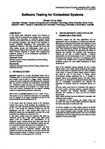
2.1 Relativized Conformance Testing An embedded system interacts closely with its environment which typically consists of the controlled physical equipment (the plant) accessible via sensors and actuators, other computer based systems or digital devices accessible via communication networks using dedicated protocols, and human users. A major development task is to ensure that an embedded system works correctly in its real operating environment. The goal of (relativized) conformance testing is to check whether the behavior of the IUT is correct according to its specification under assumptions about the behavior of the actual environment in which it is supposed to work. In general, only the correctness in this environment needs to be established, or it may be too costly or ineffective to achieve for the most general environment. Explicit environment models have many other practical applications. Figure 1 shows the test setup. The test specification is a network of timed automata partitioned into a model of the environment of the IUT and the IUT. TRON replaces the environment of the IUT, and based on the timed sequence of input and output actions performed so far, it stimulates the IUT with input that is deemed relevant by the environment part of the model. Also in real-time it checks the conformance of the produced timed input output sequence against the IUT part of the model. We assume that the IUT is a black-box whose state is not directly observable. Only input/output actions are observable. The adapter is an IUT specific hardware/software component that connects TRON to the IUT. It is responsible for translating abstract input test events into physical stimuli and physical IUT output observations into abstract model outputs. It is important to note that we currently assume that inputs and outputs are discrete (or discretized) actions, and not continuously evolving. Depending on the construction of the adapter, TRON can be connected to the hardware (possibly via sensors and actuators) with embedded software forming hardware-in-the-loop testing, or it can be connected directly to the software forming software-in-the-loop testing. We extended the input/output conformance relation ioco [17] be-
out? out!
specification
in! in? Simulated Environment
"in" "out"
input output
Implementation Under Test
Physical API
assumptions
Adapter
UPPAAL−TRON engine Environment Implementation
Adapter API
emphasis is on testing discrete mode switches (possibly non-deterministic) and on real physical time constraints (deadlines) on observable input/output actions, and less on continuous state evolution characterized by differential equations. Also many engineering based approaches has no general formal correctness criteria, and correctness is assessed manually (tool assisted) by correlating a simulated-model with observed test data. In our case we have an explicit correctness relation allowing us to automatically map events and timings into model and assign verdicts to the observed behavior online. It is also important to remark that our environment models need not represent a single deterministic scenario, but represents all relevant environment behaviors/assumptions from which samples are randomly chosen during test execution. On the other hand, the strong focus and dependency on environment models common in control engineering testing appear new to formal software testing. In Section 2 we introduce the concepts behind our testing framework. Section 3 describes the case, Section 4 our modeling experiences, and Section 5 performance results. Section 6 concludes the paper.
Figure 1: TRON test setup.
tween a formal specification and its black-box implementation to the timed setting and relatively to a given environment. Intuitively i rtiocoe s means that after executing any timed input/output trace σ that is possible in the composition of the system specification s and environment specification e, the implementation i in environment e may only produce outputs and timed delays which are included in the specification s under environment e. Relativized timed input/output conformance rtioco [6] is defined formally in Equation 1. ` ´ i rtiocoe s = ∀σ ∈ TTr(s, e). out`(i, e) after σ ´ ⊆ out (s, e) after σ
(1)
Here after σ denotes the set of states the specification system (s, e) (resp. implementation system (i, e)) `´may possibly occupy after executing the timed i/o trace σ. out denotes the possible outputs (including permissible delays) the system can produce from a given set of states. The output inclusion in the relation guarantees both functional and time-wise correctness. The IUT is not allowed produce any output actions (including the special output of letting time pass and not producing outputs in time) at a time they could not be done by the specification.
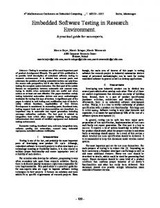
2.2 Timed Automata We assume that a formal specification can be modeled as a network of timed automata. We explain timed automaton by example, and refer to [1] for formal syntax and semantics. A timed automaton is essentially a finite state machine with input/output actions (distinguished respectively by ? and !) augmented with discrete variables and a set of special real-valued clock variables which models the time. Clocks and discrete variables may be used in predicates on transitions (called guards) to define when the transitions may take place. A location invariant is a clock predicate on an automaton location that defines for how long the automaton is allowed to stay in that location, thus forcing the automaton to make progress within the specified time bounds. On transitions, the variables can be assigned a value, and clocks may be reset to zero. Figure 2(a) shows an U PPAAL automaton of a simple cooling controller C r where x is real-valued clock and r is an integer constant. Its goal is to control and keep the room temperature in Med range. The controller is required: 1) to turn On the cooling device within an allowed reaction time r when the room temperature reaches High range, and 2) to turn it Off within r when the temperature drops to Low range. In the encircled initial location off, it forever awaits temperature input samples Low, Med and High. When C r receives High it resets the clock x to zero and moves to location up, where the location invariant x ≤ r allows it to remain for at most r time units. Edges may also have guards which define when the transition is enabled (see e.g. in Figure 2(d)). At latest when x reaches r time units the output on is generated. If a Low is received in the mean time
it must go back off. Transitions are taken instantaneously and time only elapses in locations. In location off the automaton reacts non-deterministically to input Med: C r may choose either to take a loop transition and stay in location off or move to location up. When C r is used as a specification a relativized input/output conforming controller implementation may choose to perform either. Thus non-determinism gives the implementation some freedom. There are two sources of nondeterminism in timed automata: 1) in the timing (tolerances) of actions as allowed by location invariants and guards, and 2) in the possible state after an action. Timed automata may be composed in parallel, communicate via shared variables and synchronize rendezvous-style on matching input/output transitions. In a closed timed automata network all output action transitions have a corresponding input action transition. U PPAAL is an model checker for real-time systems, and supports timed automata networks with additional integer variable types, broadcast (one-to-many) synchronizations and other extensions. U P PAAL provides an efficient set of symbolic model-checking algorithms for performing symbolic reachability analysis of timed automata. Since clock values are real-valued, the state-space of the model is infinite, and cannot be represented and computed explicitly. A symbolic state represents a (potentially infinite) set of concrete states and is implemented as particular set of linear inequations on clock variables. Thus the evaluation of guards and computation of successor symbolic states is done symbolically.
2.3 Environment Modeling In this section we exemplify how our conformance relation discriminates systems, and illustrate the potential power of environment assumptions and how this can help to increase the relevance of the generated tests for a given environment. Consider the simple cooling controller of Figure 2(a) and the environment in Figure 2(c). Take C 6 to be the specification and assume that the implementation behaves like C 8 . Clearly, C 8 rt� iocoEM C 6 because the timed trace 0·Med !·7·On! is possible`in the implementation, but not in the specification. Formally, out C 8 after 0· ´ ` ´ Med !·7 = {On!}∪R≥0 6⊆ out C 6 after 0·Med !·7 = R≥0 r (recall that C may remain in location off on input Med and not produce any output). The implementation can thus perform an output at a time not allowed by the specification. 0 Next, suppose C r is implemented by a timed automaton C r equal Low to C r , except the transition up −−→ dn is missing, and replaced by a self loop in location up. They are distinguishable by the timed trace 0·Med?·0·High?·0· Low?·0· On! in the implementation that is not in the specification (switches the compressor Off instead). Figures 2(b) to 2(e) show four possible environment assumptions for C r . Figure 2(c) shows the universal and completely unconstrained environment EM where room temperature may change unconstrained and may change (discretely) with any rate. This is the most discriminating environment that can generate any input output sequence and thus (in principle) detect all errors. This may not be realistic in the given physical environment, and there may be less need to test the controller in such an environment, as temperature normally evolves slowly and continuously, e.g., it cannot change drastically from Low to High and back unless through Med. Similarly, most embedded and real-time systems also interact with physical environments and other digital systems that— depending on circumstances—can be assumed to be correct and correctly communicate using well defined interfaces and protocols. The other extreme in Figure 2(c) is the least discriminating environment; it merely passively consumes output actions. Figure 2(d) shows the environment model E1d where the temper-
ature changes through Med range and with a speed bounded by d. Figure 2(e) shows an even more constrained environment E2 that assumes that the cooling device works, e.g., temperature never increases when cooling is on. Notice that E2 and E1 have less discriminating power and thus may not reveal faults found under more discriminating environments. However, if the erroneous behavior is impossible in the actual operating environment the error may 0 be irrelevant. Consider again the implementation C r from above. 3d r, and never under E2 for no value of d. In the extreme the environment behavior can be so restricted that it only reflects a single test scenario that should be tested. In our view, the environment assumptions should be specified explicitly and separately.
2.4 Online Testing Algorithm. Here we outline the algorithm behind TRON informally. The precise formal definitions and algorithms behind TRON have been documented in [12, 11, 6, 7] and we refer to these for further details. The environment model functions as a (state-dependent) inputstimuli (load) generator. The IUT-model functions as as a test oracle, and is used to evaluate the correctness of the observed timed input output sequence. In order to simulate the environment and monitor the implementation, Algorithm 1 maintains the current reachable symbolic state set Z ⊆ S × E that the test specification can possibly occupy after the timed trace observed so far. Based on this symbolic state-set, TRON checks whether the observed output actions and timed delays are permitted in the specification. In addition TRON computes the set of possible inputs that may be offered to the implementation. A LG . 1. Test generation and execution: Z := {(s0 , e0 )}. while Z = 6 ∅ ∧ ]iterations ≤ T do choose randomly: offer input action: if EnvOutput(Z) 6= ∅ randomly choose i ∈ EnvOutput(Z) send i to IUT, Z := Z after i delay and wait for an output: randomly choose d ∈ Delays(Z) sleep d or wake up on output o at d0 ≤ d if o occurs then Z := Z after d0 if o ∈ / ImpOutput(Z) then return fail else Z := Z after o else Z := Z after d reset and restart: Z := {(s0 , e0 )}, reset IUT if Z = ∅ then return fail else return pass TRON randomly chooses between one of three basic actions: either send a randomly selected relevant input to the IUT, letting time pass by some (random) amount and silently observe the IUT for outputs, or reset the IUT and restart. The set of input actions that are possible in the current state-set Z (enabled environment output) is denoted by EnvOutput(Z). Similarly, ImpOutput(Z) denotes the allowed set of implementation outputs, and Delays(Z) the possible delays before the tester must give an input to the IUT (as constrained by invariants the environment model). In the practical implementation the probability of restarting is chosen comparatively very low. If the tester observes an output or a time delay it checks whether
High? on
Low? x:=0
Med?
On! Med? x:=0 x:=0 Low? High? Low? Med? Med? x:=0 dn up High? x=d Med! y:=0
Off?
On?
(b) EL
High? x:=0
off
L
Off?
On?
(c) EM .
Off?
H
On?
OnLow On? y>=d Med! y:=0 Off? On? y>=d High! y:=0 Off? On?
y>=d Low! y:=0 OnMed y=d Med! y:=0 OnHigh yIUT_setPoint+diff+highAlarmDev-err newTemp?
IUT_calcTemp> IUT_setPoint+diff+highAlarmDev-err newTemp? newTemp? ta:=0 ta:=0 IUT_calcTemp=IUT_TADelay-20 ta:=0 AOn! triggered alarmOff postPoned ta