The Architecture of a Parallel Relative Debugger Greg Watson and David Abramson School of Computer Science and Software Engineering Monash University, Clayton, VIC 3168 {greg,davida}@csse.monash.edu.au Abstract Relative debugging is a technique that addresses the problem of debugging programs developed using evolutionary software techniques. Recent developments allow relative debugging to be used on programs that have been ported from serial to parallel architectures. Such programs may change significantly in the porting process, and this raises many issues for the debugging process, such as how the array data and code transformations that occur in these situations can be modelled. Relative debugging can also be effectively used in situations where the parallel programs themselves have undergone evolutionary change. This paper presents the architecture of a parallel relative debugger, and reveals a number of novel and powerful techniques that have been developed for dealing with the issues of relative debugging in a parallel environment.
1
Introduction
Relative debugging was first proposed by Abramson and Sosic in 1994 [3]. It is a powerful paradigm that enables a programmer to locate errors in programs by observing the divergence in key data structures as the programs are executing [2][4][5][6][7]. In particular, it allows comparison of a suspect program against a reference code. This becomes a particularly valuable technique when a program is ported to, or rewritten for, another computer platform. Relative debugging is effective because the user can concentrate on where two related codes are producing different results, rather than being concerned with the actual values in the data structures. Various case studies reporting the results of using relative debugging have been published [5][6][7] and these have demonstrated the efficiency of the technique. The concept of relative debugging is both language and machine independent. It allows a user to compare data structures without concern for the implementation, and thus attention can be focussed on the cause of the errors rather than implementation details. The effective implementation of a relative debugger requires an architecture that differs from traditional debuggers. The most significant requirement is the need
for a client server structure, because the system must support concurrent execution and control of multiple processes on potentially different machines. Further, the debug client must be multi-threaded to allow it to receive data from a number of independent computations. Rather than using conventional multi-threading, we use an advanced data flow technique to achieve this. Because the programs might be running on different architectures, the system must also support a data format that is independent of design parameters like word size and address type. Accordingly, we use an architecture independent data format to hide machine details from the debugger. Another important issue concerns the transformation of data structures between different versions of a program. When a program is converted from one system to another, it might be necessary to change the underlying data structures to better suite the target machine, or language. For example, one version of a program suited to a vector processor might require long single dimensioned arrays, whereas a cache based multiprocessor version might require two dimensioned arrays for efficient execution. This means that the relative debugger must be able to reverse the structure transformations seamlessly when data structures are compared. We have developed a data structure transformation algebra for the debugger that permits this seamless comparison, and we show how this is implemented. This paper presents the architecture of a relative debugger and addresses each of the issued raised above. Whilst some of the concepts have been published before [2][4][5][6][7], this paper presents a combined architecture for the first time. It also demonstrates a real implementation called GUARD-2000.
2
Relative Debugging
To the user, a relative debugger appears as a traditional debugger such as GDB [20], but also provides additional commands that allow data from different processes to be compared. The debugger is able to control more than one process at a time so that, once the processes are halted at breakpoints, data comparison can be performed. There are a number of methods of comparing data, but the most powerful of these is facilitated by a user-supplied declarative assertion. Such an assertion consists of a combination of data structure names, process identifiers and breakpoint locations.
Assertions are processed by the debugger before program execution commences, and an internal graph is built which describes when the two programs must pause, and which data structures are to be compared. In the following example the assert statement compares data from BigVar in $reference at line 4300 with LargeVar in $suspect at line 4400: assert $reference::BigVar@4300 = $suspect::LargeVar@4400 A user can formulate as many assertions as necessary, and can refine them after the programs have begun execution. This makes it possible to locate an error by placing new assertions iteratively until the region is small enough to inspect manually. This process is incredibly efficient. Even if the programs are millions of lines of code, because the debugging process refines the suspect region recursively on each iteration, it does not take many iterations to reduce it to a mere screen full of code. In more recent work, we have been examining the application of relative debugging in situations where a serial program is ported to a parallel program, or a parallel program has undergone evolutionary software development. These situations present a considerable challenge to a relative debugger. The porting process may result in significant changes to important data structures or algorithms, so the debugger must be able to take these changes into consideration when it is performing comparisons. It is also likely that the serial and parallel programs will run on different hardware platforms, so some mechanism for eliminating the effect that architecture specific information, such as byte ordering and floating point formats, may have on comparisons must be provided. The debugger must also be able to manage multiple independent processes at the same time, and these processes may reside on widely distributed systems. The latest implementation of our relative debugger, GUARD-2000 addresses all of these issues using new and powerful techniques. The debugger supports a syntax for representing the kinds of data transformations that are likely to occur through the parallelisation of serial data structures, and for some forms of code transformations. Architectural differences are eliminated by introducing an architecture independent format (AIF) layer in the debugger, and all data is translated into this format before any comparisons are performed. The debugger also provides a simulated multi-threaded dataflow engine in order to manage data flow from the many processes that may be under the control of the debugger at any one time. Finally, the debugger utilises a client/server architecture so that processes distributed systems can be controlled.
3
Debugger Architecture
The architecture of a parallel relative debugger can be separated in to two main areas: the functions that are necessary to provide debugging services in a parallel computing environment; and those that are specifically required to support the relative debugging paradigm. Parallel debuggers have existed ever since the introduction of parallel computing architectures. Most of these debuggers look and behave like debuggers for conventional architectures, but are usually enhanced to support the management and control of multiple processes. Many of these debuggers employ a client/server mechanism [9][12][16][21]. Some, such as DETOP [8] have been developed to support both task and data parallel codes. A relative debugger must also provide the functionality of a conventional parallel debugger, at least internally, because in order to carry out comparisons the debugger must ensure that processes can be distributed onto multiple platforms and can be controlled independently of one another. When the relative debugging paradigm is expanded to a parallel environment, the functionality of the debugger must be extended even further. The additional functionality that must be provided by the debugger can be loosely grouped into three categories: • relative debugging support, including the evaluation of user-defined assertions, and the storage and manipulation of data from executing processes; • parallel language support, including the ability to interpret the parallel data structures used by data parallel language run-time systems, and functionality to model parallelisation techniques; and • parallel process support, including the ability to control multiple independent processes, support for widely distributed processes, and support for heterogeneous architectures. GUARD-2000 is specifically designed to operate in a parallel environment. As well as providing traditional debugging functions, the debugger also includes a range of key architectural features to address each of the functional requirements of parallel relative debugging. These include: • • • •
a dataflow compiler and engine; an architecture independent data format; data and code transformation support; and a client/server architecture.
In addition, GUARD-2000 employs a technically advanced, highly modular architecture that incorporates a
multi-layered interface design, switchable protocols and a pluggable debugger backend.
network
This section will discuss the architecture features of GUARD-2000 in detail, and describe how they meet the functional requirements of a parallel relative debugger. 3.1
Dataflow Engine
Central to the operation of a relative debugger is the evaluation of user-defined assertions, such as those shown in section 2. The ability to define assertions over parallel programs places a significantly increased burden on the matching and control logic of the debugger. In order to support the semantics of parallel assertions the debugger must possess the following capabilities:
assert assert assert assert
In this example, the array A[100] in the sequential code has been decomposed across two slaves into the array B[50] in the parallel code. The first two assertions reflect this relationship. The second two assertions are comparing the first 10 elements of the sequential and parallel arrays at different line numbers.
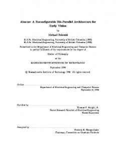
In a normal debug session, the user will define a number of assertions about the programs under consideration. As part of its user interface, GUARD-2000 provides a compiler that converts these assertion definitions into a dataflow graph consisting of nodes that define comparison and control operations, and edges that define the flow of data through the graph. When the assertions are to be evaluated, the dataflow graph is passed to the dataflow engine for execution. To begin the execution process, the graph is “seeded” with an initial token. Figure 3.1 shows a simplified graph that results from compiling the following assertions:
par.c
seq.c S
P[0]
P[1]
90
100
95
100
• it must be possible to extract data from one process independent of another; • breakpoints must be handled in any order, regardless of the static structure of assertions; • it must be possible to reuse a data item in many different assertions; and • the control mechanism must manage many processes at once. GUARD-2000 meets all of these requirements by employing a dataflow execution mechanism [1][10] to manage the evaluations of assertions. In a dataflow environment, nodes only execute when they have tokens available on all of their operands. In GUARD-2000, the assertion statement is represented as a node that performs a comparison only when it has data available on its inputs from two processes. Data from each process is encapsulated in tokens, which are generated asynchronously as the result of a process reaching a breakpoint. Since there is no guarantee data from one process will arrive at any particular time, the available data is conveniently stored until all the arguments have been generated. Similarly if two assertions require the same data item, the token is simply duplicated and sent to the appropriate input of each assertion node.
S::A[0..49]@seq.c:10 = [0]::
[email protected]:10 S::A[50..99]@seq.c:10 = P[1]::
[email protected]:10 S::A[0..9]@seq.c:15 = P[0]::B[0..9]@par.c:90 S::A[50..59]@seq.c:15 = P[1]::B[0..9]@par.c:95
100
150
A[0..9] A[0..49]
B[0..9] B[0..9]
B
A[50..99]
B A[0..9]
COMPARE
COMPARE
COMPARE
COMPARE
DISPLAY
DISPLAY
DISPLAY
DISPLAY
Figure 3.1: Dataflow graph generated from assertions
The resultant graph contains a compare node and a display node for each assertion statement. A compare node computes the difference between its arguments. If there is a difference, then this is reported to the user via the display node. The diagram shows tokens moving along then input arcs and arriving at the compare nodes at different times. Once a compare node has tokens on both its inputs, it will perform the comparison and then send the result to the display node. A few debuggers have used dataflow as a control mechanism in the past [15][18]. In [18] this was concerned with using the breakpoint as an event trigger for a piece of debugger code. Likewise TotalView [21] allows the user to write expressions that are executed when a breakpoint fires, and these can be considered like dataflow expressions. GUARD-2000 extends previous work significantly by building complex tokens containing data from the processes being debugged, and then using this data in the assertion statements. 3.2
Architecture Independent Data Format
In addition to debugging programs on physically separate hosts, a relative debugger must also support programs running on heterogeneous architectures. Data from remote systems must be transferred to the client as a
result of formatting or display commands, or for arithmetic or comparison operations generated by the dataflow engine when executing assertions. The remote systems (and the client) may each employ different architectural features such as word length and byte ordering. The problem of sending architecture specific data over a network has been addressed by standard networking protocols such as XDR [19]. Much work has also been done on the development of architecture independent file formats, with NCSA’s HDF [17] now accepted as the defacto standard. However, none of these approaches address the issues of performing in-memory operations on data from architecturally different systems. As a result, GUARD-2000 provides a well-defined API and library routines that implement all the necessary arithmetic and conversion operations. AIF is designed to achieve true architecture independence for arbitrary data types. The key components of the AIF system are: • a format for representing data in an architecture independent manner; • routines for converting to and from native formats; • routines for performing arithmetic, logical and comparison operations on AIF data; • routines for accessing components of structured data types; and • routines for performing I/O on AIF data. Table 3.1: AIF Format Descriptor Tags
Tag
Type
cs
character
isl
integer
fl
floating-point
^lt
address
[t1]t2
array
{l=f1@o1#l1:t1,…, fn@on#ln:tn}
structure or union
enumeration
rvmin..vmaxt
range
Vl
void
Rrt
ZPL region
s is s (signed) or u (unsigned), l is size in bytes, t is type, f is a field name, o is field offset in bits, n is size in bits, e is enum name, v is enum value or range bounds, r is rank.
Data is represented in AIF using two components: a data tag and a normalised bit stream. When data is converted to AIF, a series of normalisation operations are performed. These include the conversion of integers to
big-endian byte ordering, characters to the ASCII collating sequence and floating-point number to the IEEE 754-1985 big-endian format [14]. The format also standardises on a byte size of 8-bits and single byte characters. Since the normalisation operations can result in the loss of native format information, the bit stream is tagged with a format descriptor string (FDS). Table 3.1 lists the current format descriptor tags. Tags for simple data types provide AIF library routines with information such as the size of the data and whether the data is signed or unsigned. This allows different integer sizes and single, double, and extended floating point formats to be supported, and ensures that the AIF library routines can perform calculations with no loss of precision. Complex data types have tags that describe the size and memory layout of the data, and can contain nested tag types. Figure 3.2 shows an example of how a C structure is represented in AIF. C STRUCTURE
AIF REPRESENTATION
FDS {16=a@0#32:is4,b@32#72:[r0..2is4]f4}
struct { int a; float b[3]; };
StructToAIF()
DATA byte 1
byte 2
byte 3
s exponent
mantissa
s exponent
mantissa
s exponent
mantissa
byte 4
Figure 3.2: AIF Representation of a C Structure
Data is converted into AIF using one of the data conversion routines. Routines are provided to convert simple data types, such as IntToAIF() and FloatToAIF() and complex data types, such as ArrayToAIF() and StructToAIF(). All the data conversion routines return a pointer to an AIF structure that holds the data and tag information. This pointer can then be used as an argument to the other AIF routines. Routines are also provided to convert AIF data back to native format. Once data is converted to AIF it can then be manipulated using the arithmetic and logical operations. Routines are also provided to access and manipulate complex data types, such as indexing elements of arrays, iterating over array indices or retrieving structure fields. In addition, routines are available to perform I/O on AIF objects, such as reading from and writing to files. The current implementation provides descriptors for C, Fortran, and ZPL. Support for another language can be added by defining new descriptors for each of the languages data types that are not covered by the current descriptors, and by providing routines to perform appropriate operations on these data types.
3.3
Data Transformation Functions
A key component of parallel relative debugging is the ability to compare data structures between serial and parallel codes. The type of transformations that are used when a serial code is converted to execute on a parallel computer become particularly important, as the user may wish to compare data structures at various places without concern for the different organisation of the data in the two programs. In order to achieve this, the debugger must provide a mechanism to replicate the transformations that have been applied to the programs. It is desirable that this mechanism is implemented by the debugger in a way that is transparent to the user, so they can concentrate on identifying the location of the error. GUARD-2000 supports four types of transformations to assist the user in debugging parallel codes. The transformations are specified in the debugger using a special syntax. This syntax is in turn derived from a transformation algebra that has been developed to model the different types of data transformations. The algebra and its associated syntax are beyond the scope of this paper, however of the transformation types are discussed in more detail below. 3.3.1 Data Parallel Decomposition Except for extremely coarse-grained or parameterised models, parallelisation of an algorithm on a MIMD computer usually requires some form of decomposition of arrays in order to distribute data to the individual processes. In the case of data parallel languages, this decomposition is usually a block or cyclic decomposition, or a combination of the two, and is handled automatically by the language runtime system. In many cases, particularly where process pool sizes are dynamic, the exact partitioning is not normally known until runtime. SERIAL DATA
DATA DECOMPOSITION
PARALLEL DATA
DATA COMPARISON
compare
map
Figure 3.3: Data Distribution and Mapping
GUARD-2000 is able to deal with most of these situations using a map notation. This allows the decomposition model to be described in terms of two functions: a function of the array indices and a function of
the processor number. When combined together, these functions form a map that can be applied to the parallel data in order that a comparison can be made. Figure 3.3 shows how this mapping process applies to data comparison. 3.3.2 Shape Transformations It is sometimes necessary to actually change the data structures of a program in order to implement a parallel version of the algorithm. For example, data may be structured to exploit particular vector architectures and this data may need to be organised into an array to allow parallelisation. Alternatively, the shape of arrays may need to be altered to exploit processor performance improvements, for load balancing purposes, or for better cache utilisation [7]. VECTOR
3-D ARRAY 2-D ARRAY
flatten
block
Figure 3.4: Array Shape Transformation
GUARD-2000 provides a shape transformation mechanism using standard flattener and blocker functions. The flattener function takes a multi-dimensional array and linearises it. The blocker function takes a vector and blocks it into a multi-dimensional array. By ensuring that the number of elements in the arrays always remains constant, we have a mechanism that will transform an ndimensional array into an m-dimensional one. Figure 3.4 shows an example of transforming a 2-dimensional array into a 3-dimensional one. 3.3.3 Index Permutation Programs that have been optimised for a vector processor may scan the data in a particular way, but this may not be appropriate for a cache based parallel machine. Accordingly, permutation of array indices is often required to improve data locality and to exploit the processor cache. In addition, permutation may also result from language differences, such as between C and Fortran. In this case, one language uses row-major order, the other column-major. The permutation necessary to compare arrays from these languages is shown in Figure 3.5.
nXm
mXn
Figure 3.5: Index Permutation
Conveniently, index permutation turns out to be a special case of data distribution where the mapping is from one serial process to another. Accordingly, GUARD-2000 uses the same map notation to define index permutation. 3.3.4 Temporal Displacement Variable re-use is a common programming construct. When this occurs, a scalar value may be calculated, used and then overwritten in a new computation, usually within some form of loop construct. However, when this type of program is parallelised, it is often necessary to promote the scalars to an array, one unique value per loop iteration. Such a variation between the sequential and parallel codes makes it extremely difficult to compare the data, because there may be no point in time in which the data exists concurrently in both programs. Figures 3.6a and 3.6b show how a scalar variable TEMP is used in a Fortran code is replaced with an array temp in the C code. To compare these values, a copy of the scalar must be made on each iteration of the loop. When the loop has completed these copies can then be compared to the C array.
80
90
DO 90, I TEMP = X(I) = Y(I) = CONTINUE
= 1, 100 X(I) * Y(I) 2 * Y(I) PI * TEMP
(a) Fortran Code
128 129 130 131 132 133 134 135 136 137
for (i=0; i