Advanced Science and Technology Letters Vol.138 (ISI 2016), pp.93-98 http://dx.doi.org/10.14257/astl.2016.138.21
The Fault Detection by the Dynamic Pattern Test through ASIC Data Extraction and Analysis DoHyun Kim1, Woo-Jae Shim2, Seung-Beom Hong1,1 1 Division of Aeronautical Studies, Hanseo University, Taean-Gun, Chungcheongnam-Do, 32158 Republic of Korea {sbhong, dhkim}@hanseo.ac.kr 2 Department of Avionics Engineering, Hanseo University Graduate, Taean-Gun, Chungcheongnam-Do, 32158 Republic of Korea {bc403kr}@naver.com
Abstract. If there don’t have the Test Requirement Document (TRD), it is impossible to analyze the operation of circuit and detect the fault in ASIC. Therefore, we created the TRD based on analyzed logic data extracted from ASIC, and diagnosis on the ASIC circuits at the point of level of gate. Also test board is controlled by signal of I/O pins utilizing Dynamic Pattern Test. We could identify the 17 pattern from tests, and figure out faults in 16 addresses. According to the experiment for target board applied with proposed methods, it is possible to diagnose fault for abnormal computerized chip, ASIC, by utilizing test unit board. We’ve also obtained the excellent performance for fault detection. Keywords: TRD (Test Request Document), Dynamic Pattern ATE(Automatic Test Equipment), Fault Detection, Data Mining
1
Test,
Introduction
In accordance with the development of an integrated semiconductor, the ASIC (Application Specific Integrated Circuit) has rapidly developed the level of the integration in the semiconductor on the digital system of the aircraft’s avionics equipment. Because the trend to use ASIC is shrink in size and provide higher function densities and faster working speeds, while consuming less power and taking less area and weigh on the boards, ASIC increases in its usage in the field of electronic industries [1-4]. Not only ASIC but also IC (Integrated Circuit) devices may be produced with imperfect function in their manufacturing processes. In general, test methods for ASIC/IC are both hardware based BIST (Built-in Self-Test) and software based LASAR (Logic Automatic Stimulus and Response). The BIST method is a form of self-test which is built into integrated circuits allowing self-test algorithms to examine their own operation, as opposed to reliance on external automated test equipment [5]. 1
Corresponding author : Seung-Beom Hong, +82-41-671-6231,
[email protected]
ISSN: 2287-1233 ASTL Copyright © 2016 SERSC
Advanced Science and Technology Letters Vol.138 (ISI 2016)
And LASAR method utilized as standardized test program to defense industries in the United States is a technique for detecting defects which fault dictionary generated a database of fault model at the test unit board [6], [7]. If it wants to the best performance of result from test methods. Both BIST and LASAR methods must have the test requirement information for ASIC. However, if there is not test requirement information in test target board, it is difficult to detect faults of ASIC. In the case of no standard operating procedure such as TRD (Test Requirement Document), it is impossible to analyze the operation of the circuit and detect the fault in ASIC. Therefore, in this paper, we suggest the Dynamic Pattern test method which created the TRD based on analyzed logic data extracted from ASIC and diagnosed on the ASIC circuits at the point of level of gate. Therefore, if we have got result of numerous signal patterns in test unit board as much as we could, it will significantly improve fault detection ratio in ASIC.
2
Dynamic Pattern Test for fault detection
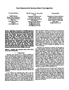
In case of unknown TRD for the test unit board exists, it is impossible to take the fault diagnosis. It requires the TRD to analyze the confidence of fault detection on test unit board. Therefore, it makes the TRD based on the analyzed logic data of the ASIC, and diagnoses of the ASIC circuit at the gate level through the signal control of I/O pins using the Dynamic Pattern Test [7], [8]. There is methodology on processing for each steps as shown in Fig. 1. Firstly extraction and analysis step at the ASIC as shown in Fig 1 (i) & (ii), extracts JEDEC files through the ROM writer from ASIC and converts into the logic equation text file utilizing JEDEC TO LOGIC EQUATION program. The text file can be redesigned from an equation text file into an OR-CAD EDA tool, which is circuit design program. We are able to simulate the redesign logic, analyze outcome from in/output and power/ground port and generate TRD with dynamic pattern test signals. Secondly, connect hardware between test unit board and ATE (Automatic Test Equipment) which is any apparatus that performs tests on a device, known as the Device Under Test (DUT) or Unit Under Test (UUT), using automation to perform measurements and evaluate the test results [9]. As shown in Fig. 1 (iii), ITA is the device electrically interconnected with the test unit board in the middle to make it tested possible in ATE [10]. And ITA are produced. The fault diagnosis will be carried out. At the TRD production step as shown in Fig 1 (iv), each signal title, input data and comparable output data shall be categorized and based on Dynamic Pattern signals will be created. Finally, faults will be diagnosed by realizing the function of circuit board mounted with ASIC by running the test program after installing the test unit board in ATE. If the data flowing through the pattern has no problem, it is considered as PASS, and if fails, abnormal signal occurs to notice the fault was found to the user, which enables to diagnose the fault.
94
Copyright © 2016 SERSC
Advanced Science and Technology Letters Vol.138 (ISI 2016)
Fig. 1. The procedure of Dynamic Pattern Test system
3
Experimental Results
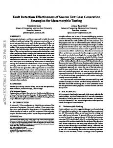
Test unit board has extracted software from ASIC to handle centralized control of the radar signal processor. We analyzed logic data mounted on ASIC replaced to PALCE16V8 class EE CMOS 20-PIN UNIVERSAL PROGRAMMABLE ARRAY LOGIC manufactured by the ATMEL Company. ATE uses the Teradyne Inc. M9series Digital Test instrument and the dynamic pattern signal code has been implemented to Visual C++ 8.0. To accurate fault detection, it connects the test unit board to ITA and applies the control signal to ATE as shown Fig. 2. According to the Dynamic Pattern Test signal, if the test unit board is operating normally by the Dynamic Pattern signal, it is considered as PASS, and if abnormal operation, it can diagnose the fault.
Copyright © 2016 SERSC
95
Advanced Science and Technology Letters Vol.138 (ISI 2016)
Fig 2. Fault signal detecting method
As described above, we could identify that there was no problem in data transmission in case of normal condition. Fig. 3 illustrates the result after comparing the response applied with data signals, coded into the test program. Fig. 4 is the result to identify data, applied to signals on the test board, which has been detected as a failure. As a result for comparison of 17 data by each addresses, we could figure that faults exist in 16 addresses. Those faults, demonstrated in accordance with the test result, should be checked in the failure inducing devices tracked down by the user.
Fig.3. Normal Test Results
96
Copyright © 2016 SERSC
Advanced Science and Technology Letters Vol.138 (ISI 2016)
Fig.4. Abnormal Test Results
4
Conclusion and Future works
In this paper, we extracted JEDEC file targeting this ASIC by utilizing the program for general purpose on logic data of internal ASIC, and, the logic simulation was possible based on the extracted data and the logic simulation was also possible by using the extraction of circuit design. Based on the analyzed data, we developed the test program to control the test, and applying to ATE, we realized the fault research possible. And to the series of procedures analyzing the internal logic of the extracted ASIC, the TRD was developed. Consequently, we verified that the fault diagnosis is possible in the process of analyzing the internal data of ASIC and applying it to the test and the interconnection with ambient devices. In addition, without using the existing LASAR but by using Dynamic Pattern, it was possible to diagnose the faults through controlling the signals of in/output pins at the gate level for the ASIC circuit board. However, as such algorithm was applied to a specific ASIC and the ASIC unable to extract more integrated and functionalized internal logic was impossible to be analyzed, it is indeed that more researches and efforts may be required for applying the methods suggested by this paper. Therefore, it remains a challenge to evolve through a further study in order to the similar test devices.
Copyright © 2016 SERSC
97
Advanced Science and Technology Letters Vol.138 (ISI 2016)
References 1.
Shim, W.J., Jung H.S., Kang C.H. Jie M.S. Hong G.Y., Ahn D.M., Hong S.B.: A Study on the Fault Detection of ASIC Dynamic Pattern Method. In: Journal of Korea Navigation Institute (JKONI), Vol 17, No 5, pp.560-567, (2013) 2. Kim, W.J., Jeong, H.B.: Automotive Electronic Systems/Semi-conductor Industry and Technology Trends. In: National IT Industry Promotion Agency, (2012) 3. Gardenyes, R.B.: Trends and patterns in ASIC and FPGA use in space missions and impact in technology roadmaps of the European Space Agency. In: Master Thesis, Delft University of Technology, Netherland (2012) 4. Fernandez-Leon, A.: Microelectronics: ASIC and FPGA. IN: European Space Agency: Noordwijk, Netherland (2012). 5. http://en.wikipedia.org/wiki/Ligic_built-in_self-test 6. http://www.teradyne.com/products/defense-aerospace/lasar 7. Jung, J.K.: Implementation of the Fault Detecting System by the Extracting the ROM’s Data, Master Degree dissertation, Hanseo Univ., Taean Chungcheong, (2012) 8. MIL-STD-1345B.: Test Requirement Document (1981) 9. http://en.wikipedia.org/wiki/Ate 10. Teradyne Inc.: M9-Series Digital Test Instrument Manual (2012)
98
Copyright © 2016 SERSC