IEEE TRANSACTIONS ON NUCLEAR SCIENCE, VOL. 52, NO. 5, OCTOBER 2005
1679
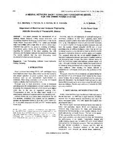
The Global Trigger Processor Emulator System for the CMS Experiment T. Geralis, S. Kyriazopoulou, C. Markou, I. Michailakis, and K. Zachariadou
Abstract—We present the development of the global trigger processor emulator system (GTPe) for the CMS experiment data acquisition system (DAQ). The GTPe generates Level-1 triggers and exchanges information with other DAQ components. The GTPe is an FPGA-based PCI card operating in a host Linux PC. The board is programmed to function as a trigger data source, capable of generating multiple independent triggers and their associated data streams. Data are transmitted over the CMS-specific S-LINK64 protocol. The purpose of the GTPe is to decouple the Leve1-1 trigger system from the readout system. This is an important component of the installation, testing, and maintenance of the CMS DAQ. Index Terms—Data acquisition, digital circuits, elementary particles, field programmable gate arrays, logic design, triggering.
I. INTRODUCTION
I
N THE CMS experiment data acquisition system (DAQ) (Fig. 1), the detector front-end electronics are read out in parallel by multiple units which format and store the data in deep buffers. These buffers must be connected to the processors in the high-level trigger farm via a large switch network (Readout Builder). Two systems complement the flow of data from the frond-end electronics to the processor farm: the event manager (EVM), responsible for the actual data flow through the DAQ; and the control and monitoring system, responsible for the configuration, control, and monitoring of all the elements [1]. The CMS DAQ system is composed of eight vertical slices, each of them capable of operating more or less independently from the others. These are called DAQ partitions. The detector is divided into 32 subdetector parts, any combination of which can form a DAQ partition. Since the system accommodates up to eight DAQ partitions, there are eight EVMs, Readout Builders, etc. (Figs. 1 and 2). In the CMS DAQ, the global trigger processor (GTP) calculates up to 128 different trigger conditions and combines them into a Level-1 Accept (L1A) signal for every beam crossing (25 ns). The GTP drives all eight DAQ partitions in parallel, although only one partition is triggered at any given time. The L1A signal is sent to all the front-end drivers of the subdetectors and the EVMs via the timing, trigger, and control (TTC) optical network. Furthermore, it regulates the sending of its triggers in response to feedback from the asynchronous (aTTS) and synchronous (sTTS) trigger throttling systems. At the same time,
Manuscript received November 8, 2004; revised April 13, 2005. The authors are with the Institute of Nuclear Physics, NCSR Demokritos, GR-15310 Ag. Paraskevi–Attiki, Greece (e-mail:
[email protected];
[email protected];
[email protected]; imich@ otenet.gr;
[email protected]). Digital Object Identifier 10.1109/TNS.2005.852650
the GTP guarantees that the sequence of L1A complies with a set of trigger rules of the general form, “There should be no more than a certain number of triggers within a given time interval,” in order to minimize the likelihood of buffer overflow of the subdetectors. Detailed description of the GTP can be found in [2]. The GTPe will be part of the final DAQ system connected in parallel with the GTP system. During the DAQ system installation, the GTPe will be used to decouple the Level-1 trigger system from the readout system (Figs. 2 and 3). The GTPe will be a necessary tool for the development of the DAQ system, particularly concerning its partitioning capabilities, as well as for testing the performance of the DAQ components during the development phase. It will also be used for debugging and upgrading purposes in the final DAQ system. There, it will be perEVM switch manently connected to one of the inputs of the (Fig. 2). II. THE GTP EMULATOR SYSTEM A. Overview The GTPe system performs the following functions. 1) Random generation of L1A triggers for each partition. These are generated at a user-defined rate, timed to coincide with nonempty beam crossings. Moreover, the delivery of L1A triggers complies with a set of trigger rules imposed by the subdetectors parts of each partition. L1A triggers are sent via a distribution system used to broadcast signals to the FRLs. 2) Partitioning–there are eight DAQ partitions. Each DAQ partition can include any combination of the subdetector’s parts [1]. 3) Emulation of the LHC proton beam structure. 4) Generation of trigger summary pseudodata, encapsulated in the FED Common Data Format [1]. 5) Receipt of feedback signals from DAQ partitions (aTTS) and from subdetectors’ parts (sTTS). 6) Transmission of status signals to the run control. B. The GTPe Implementation The GTPe must produce triggers according to Poisson statistics; hence, events will frequently occur in successive bunches. For that reason, the GTPe must perform the following in every clock cycle (25 ns): the generation of random numbers, the L1A decision, the bunch-crossing calculation, the orbit calculation, the event counting, and the implementation of trigger rules. Above all, some detectors may require a reset at every orbit, and test triggers may be sent at the 3 s dead-gap in every LHC
0018-9499/$20.00 © 2005 IEEE
1680
IEEE TRANSACTIONS ON NUCLEAR SCIENCE, VOL. 52, NO. 5, OCTOBER 2005
Fig. 1. Three-dimensional schematic of the CMS DAQ system [1].
Fig. 2. GTP and the GTPe in the CMS DAQ. They can drive up to eight DAQ partitions, one of which is shown here.
orbit. The system must provide this kind of signal with the required precision of one LHC clock. A fully hardwired solution is adopted to fulfill the above requirements. The GTPe system is based on a generic, multipurpose PCI card (Generic III or GIII) [3], developed within the CMS DAQ group. The GIII is a PCI (64 bits at 66 MHz) board featuring a single FPGA (APEX with 400k gates, from Altera), 1 MB flash
Fig. 3. GTPe allows the DAQ system to be disconnected from the Level-1 trigger system. In dots are the DAQ components that do not communicate directly with the GTPe.
RAM, a 32 MB SDRAM, a set of user’s connectors, plus connectors compliant with the S-LINK64 [simple link interface in
GERALIS et al.: THE GLOBAL TRIGGER PROCESSOR EMULATOR SYSTEM
Fig. 4.
Close-up view of the GTPe.
a common mezzanine card (CMC)] [4] pin-out. The GIII board is plugged into a PC running Linux OS. The GTPe is controlled via the PCI bus by dedicated user’s interface processes. For development purposes, the data fragments are transferred via the SLINK-64 protocol into a second GIII board (receiver), and are retrieved by dedicated readout software. The core of the GTPe is designed with the help of two different tools: Quartus 2.2 (Altera) [5] and DK1 1.1 (Celoxica) [6], combining the efficiency of a low-level VHDL and the advantage of a hardware-oriented high-level language (Handel-C). The firmware for the PCI controller, the SLINK-64 controller, and the JTAG has been developed using Quartus 2.2, whereas the firmware for the GTP emulation has been developed using DK1 1.1. The GTPe complex hardware logic and the requirement for full parallelism are facilitated using Handel-C. We designed the GTPe-IO module to provide an interface of the GTPe to the trigger distributor and throttling systems. GTPe-IO is based on an Altera ACEX 30k and is housed in a 19-inch box provided by Elma Electronics. The connection of the GTPe-IO to the GTPe is made using a CMC plugged on the fast GIII connector (Fig. 4). A detailed description of the interfaces is given in Section III. C. The GTPe Design The main functional blocks of the GTPe design are shown in Fig. 5. The LHC proton beam structure is emulated by the BX_gen module. This structure is rather complex, with series of full bunches followed by empty ones. The total orbit length is 3564 bunch-crossing intervals (89 s), and the proton bunches are grouped in 39 trains, 72 bunches each. At the end of the orbit, there is a period of 119 missing bunches (3 s long). The LHC bunch-crossing frequency is provided by a 40-MHz quartz situated on the GIII board. The beam structure signal (BX) is fed to the Level-1 generator module (L1_Gen). The L1_Gen module receives the DAQ partitions definition and their associated frequency settings from the PCI bus. The DAQ partition definition specifies the subdetector parts belonging to that partition. At any given time, only
1681
one DAQ partition is triggered. This is done randomly according to its preset frequency. Random number generators are implemented and used for the L1A decision only at nonempty bunch crossings. The L1_Gen module associates with every L1A signal the following data: 1) a bunch-crossing number (12 bits) counting the number of bunch crossings within each LHC orbit; 2) an event number (24 bits) counting the number of L1A signals per DAQ partition; 3) a trigger number (24 bits) counting all the L1A signals generated since the last GTPe reset; 4) a 3-bit number indicating the triggered DAQ partition; and 5) an orbit number (32 bits) counting the number of orbits since the last GTPe reset. The above data are formatted with the common FED data encapsulation format as seven 65-bit words to form a trigger data fragment [1]. The 65th bit distinguishes the header and trailer words from the data words. A standard cyclic redundancy code (CRC) is performed on every trigger data fragment to ensure error-free data transfer. CRC is calculated using a synthesizable polynomial function from the IEEE library [7] The assertion of Level-1 triggers follows a set of subdetector trigger rules which are implemented in the L1_Gen module (Table I). The L1_Gen module receives feedback signals interpreted as an inhibit of all L1A triggers from: 1) the DAQ partitions (aTTS_busy); 2) the subdetectors parts (sTTS_busy); 3) the S-LINK64 controller (LFF or EVM_BUSY) (Fig. 5); and 4) the internal cyclic Write_Evm event buffer (WR_buf). The Write_Evm module receives all the data fragment words in parallel, and temporarily stores them in a cyclic event buffer of four-events length (Fig. 5 inputs d0-d6). The buffering is necessary to serialize the output data stream, and to avoid dead time when triggers occur in successive bunches. Data fragments are sent to the local FIFO, so long as at least 16 locations are available. The FIFO data is sent over the S-LINK64 upon receipt of a read command (Section II-E). Furthermore, event losses and dead-time statistics are kept in counters that can be read by the host PC over the PCI bus. D. PCI Controller The PCI controller provides PCI communication plus registers for control, status, error, and reset operations. In total, there are 13 registers that can be accessed through the PCI bus. For example, accessing the command register (GTPe_cmd), the user can start, stop, and reset the GTPe (Fig. 5); accessing the partition-definition register, the user can select the subdetector parts belonging to a DAQ partition and set the trigger rate. Trigger rates can be modified on the fly. E. S-LINK64 Controller To transfer the GTPe data fragments, the S-LINK64 protocol is used. Detailed description of the S-LINK64 can be found in [4]. Upon the reception of the write-enable S-LINK64 command from the PCI controller, the S-LINK64 controller initiates the reading of the local FIFO, so that data start to flow to the receiver side. Backpressure signal LFF is sent to the L1_Gen module
1682
IEEE TRANSACTIONS ON NUCLEAR SCIENCE, VOL. 52, NO. 5, OCTOBER 2005
Fig. 5. GTPe functional block diagram. TABLE I TRIGGER RULES
when the receiver cannot accept more data or the receiver is not running. Fig. 6. GTPe interfaces schematic.
III. INTERFACES The GTPe system’s hardware interfaces are shown in Figs. 6 and 7. The interface to the throttling and trigger distributor systems is implemented in hardware via the GTPe-IO module, while the interface to the EVM is performed via the S-LINK64 mezzanine card, to which we have already referred. The GTPe-IO module is specially designed and built to interface the GTPe TTL signals to LVDS signals for the communication with the trigger and throttling systems, and to encode or decode 4-bit states to 2-bit states that the GTPe is handling. The LVDS standard is selected by CMS collaboration to allow efficient communication with the dispersed distant systems. The general schematic of the GTPe-IO module, which is based on a 30-k gates Altera FPGA is shown in Fig. 8. A mezzanine card is plugged on GTPe to provide connection to GTPe-IO via two RJ45 connecflat cables. GTPe-IO’s front panel provides tors and 12 Lemo connectors (eight for the L1A signal and four to spare). The GTPe-IO back panel provides the connectors for
Fig. 7. GTPe-IO module (left), the GTPe system (middle), and the EVM receiver board (right) are shown, together with the connection of GTPe to/from GTPe-IO (flat cable), and the connection to EVM receiver (S-LINK64 cable).
GERALIS et al.: THE GLOBAL TRIGGER PROCESSOR EMULATOR SYSTEM
Fig. 8.
1683
GTPe-IO module schematic.
the flat cable, and a JTAG connector for reconfiguring the FPGA (Fig. 8). Summarizing, the GTPe is connected to the following systems. 1) Trigger Distributor: GTPe distributes eight L1A signals to the triggered DAQ partitions. GTPe-IO provides the signals via eight Lemo connectors in TTL (5 Volts). 2) The asynchronous throttling system (aTTS): Input: Each of the eight DAQ partitions transmits to GTPe four LVDS signals (READY, BUSY, OUT_OF_SYNC, and WARNING). The encoding of this 4-bit state is the standard CMS encoding, as it is described in the TCS note [8]. If a partition sends a not READY signal, the GTPe inhibits L1A for this DAQ partition. Outputs: The GTPe sends the status of each of the eight DAQ partitions to the Run Control, indicating whether a partition is configured to run. The status signals are labeled as the input signals. 3) The synchronous throttling system (sTTS): Input: Each of the subdetector parts transmits to GTPe four LVDS signals labeled as above. If a subdetector part sends a not READY signal, GTPe inhibits L1A for the DAQ partition in which the subdetector part belongs. 4) The EVM: The GTPe system, for every L1A, transmits the data fragment to an FRL that broadcasts it to the EVM ). Subsequently, the switch directs the FED switch ( fragment to the corresponding partition EVM. Connections 1–3 are implemented via the GTPe-IO, while connection 4 is implemented via the S-LINK64. IV. PERFORMANCE TESTS
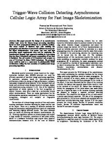
module. GTPe sends event fragments, via the S-LINK64, into a second GIII card (receiver) plugged into another Linux PC. The GPTe is controlled and configured via a set of PCI registers (see Section II-E). To control GTPe, we have developed two applications, one based on LabView [9], and the second based on a C-language hardware-access library. Both applications can be used in standalone mode, but the C-application is suitable for the GTPe integration in the CMS DAQ system. The FED-kit readout software [3] has been used to read and analyze the data online, on the receiver side. Two different sets of tests have been performed using this testbench. In the first test, GTPe runs in full speed (more than 100 kHz), but with a slow readout rate, limited to 20 kHz. The slow event consumption causes a highly frequent backpressure to GTPe. Data arriving via the S-LINK64 are dumped onto the receiver PC’s hard disk and are analyzed offline, in order to verify that the system responds adequately to the S-LINK64 backpressure and that the LHC beam structure is correctly reproduced. In the second test, fast readout measurements have been taken, and data are read and analyzed online at full speed. Trigger number, partition event number, and trigger rules have been verified for a large number of accumulated events (up to ). The tests have been performed for trigger rates from 10 to 250 kHz, and for different DAQ and subdetector partition schemes. Omitting the trigger rules, the trigger rate was pushed up to 5 MHz and no malfunction was observed, hence, the system has been proven to run properly in extreme conditions.1 The synchronization of the L1A signal with the corresponding events, using a event fragment has been verified up to fast CAEN counter timer. Moreover, the event timing has been tested at various trigger rates. A slightly deformed Poisson distribution is observed; the deformation is due to the trigger rules and the empty bunches in the LHC beam structure (Fig. 9).
A testbench has been set up in order to test the performance of the GTPe system. It is based on a Linux PC hosting the GTPe
1On every L1A, a data fragment (seven data words) plus one control word are transferred via the S-LINK64, requiring eight clock cycles
1684
IEEE TRANSACTIONS ON NUCLEAR SCIENCE, VOL. 52, NO. 5, OCTOBER 2005
Fig. 9. Probability of observing a subsequent trigger as a function of time for events generated at 120 kHz. Fewer entries in the first bin and rather bad high square (even omitting the first bin) are due to the trigger rules and the empty bunches in the LHC beam structure.
Even though the CMS DAQ system is not yet fully integrated, basic tests for the GTPe integration in the CMS DAQ have already been performed. The whole chain, from GTPe to the EVM, was tested. A GTPe module was connected to a FRL. The data fragments were consequently sent via the FRL Lan-i10 network card through a Myrinet switch (FED Builder EVM switch—see Figs. 2 and 3) to a PC (EVM). The system ran at 123 kHz frequency for one partition, and presented no error for events). The throttling backabout six hours (about pressure signals have been tested successfully using an autotest mode. V. CONCLUSIONS We have developed a global trigger processor emulator system (GTPe) that fully emulates the GTP of the CMS DAQ system. The GTPe aims at decoupling the L1 trigger system from the readout system for testing, installation, and maintenance purposes. It is a highly complex system with the same capabilities as the real GTP, apart from its connectivity to the
LV1 system. The GTPe generates L1A triggers, applies partitioning, emulates the LHC proton-beam structure, generates trigger data fragments, and receives feedback signals from DAQ partitions and subdetector parts. The data generation and trigger rules implementation is performed in every clock cycle (25 ns), hence, full parallelism is implemented. The GTPe’s nominal operating frequency is 100 kHz, on average, but the system is tested to function properly up to 5 MHz. Since the generation of L1A triggers is random, instant rates may reach 20 MHz. Even though GTPe generates pseudorandom triggers, its operation is nearly realistic because of asynchronous arrivals of backpressure signals. The GTPe system is based on a generic PCI card featuring a single FPGA. The core of the GTPe is designed with the help of two different tools combining the efficiency of a low-level VHDL and the advantage of a hardware-oriented high-level language (Handel-C). The GTPe complex hardware logic and the requirement for full parallelism are facilitated using Handel-C. The GTPe will be a necessary tool for the development of the DAQ system, particularly concerning its partitioning capabilities. The GTPe will be part of the final DAQ system of the CMS experiment. ACKNOWLEDGMENT The authors wish to thank C. Schwick, D. Gigi, and E. Cano for their constant support during the development and testing of the GTPe system. Fruitful discussions with S. Cittolin, F. Meijers, and J. Varela are gratefully acknowledged. They would like also to thank their technicians with NCSR, D. M. Tsopanakis and L. Saragas, for their excellent work on the mechanics and the mounting of the cards. REFERENCES [1] “The Trigger and Data Acquisition Project, Vol. II, TDR,” CMS Collaboration, CERN/LHCC 2002/026. [2] “The Trigger and Data Acquisition Project, Vol. I, TDR,” CMS Collaboration, CERN/LHCC 2000/038. [3] E. Cano and D. Gigi, FEDKIT User’s Manual and Programer’s Manual, vol. 9, CMS Collaboration, CERN. [4] A. Racz, R. McLaren, and E. van der Bij. The S-LINK 64-bit Extension. [Online]. Available: http://hsi.web.cern.ch/HSI/s-link/spec [5] Quartus II, Development Software Handbook. San Jose, CA: Altera. [6] DK1 Design Suite Datasheet. Oxfordshire, U.K.: Celoxica. [7] Generation of Synthesizable CRC Functions in VHDL. Leuven, Belgium: Easics. [8] J. Varela, “CMS L1 Trigger Control System,”, CMS Note 2002/033. [9] LabView User Manual. Austin, TX: National Instruments.