Proceedings of the ASME 2013 32nd International Conference on Ocean, Offshore and Arctic Engineering OMAE2013 June 9-14, 2013, Nantes, France
OMAE2013-10959
THE SHIP-ROUTING OPTIMIZATION BASED ON THE THREE-DIMENSIONAL MODIFIED ISOCHRONE METHOD Yu-Hsien Lin* Department of Mechanical Engineering University of California at Berkeley Berkeley, California 94720, U.S. Email:
[email protected]
ABSTRACT In this paper, the authors proposed a ship weather-routing algorithm based on the composite influence of dynamic forces, i.e. wind, wave and current forces, for determining the optimized transoceanic voyages. Our developed routing algorithm, three-dimensional modified isochrones (3DMI) method, utilizes the recursive forward technique and floating grid system for both the east- and west-bound ship routes in the North Pacific Ocean. In order to achieve the goals of minimized fuel-consumption or the maximized-safety routes for the transoceanic voyages, two sailing methods are applied as the prerequisite routes in the earth coordinate systems. The illustrative analysis of ship routes has been presented and discussed based on the realistic constraints, such as the presence of land boundaries, non-navigable sea, external forces, parametric roll responses as well as ship speed loss. As a result, the proposed calculation is verified to be effective for the optimized sailings by adjusting the weighting parameters in the objective functions.
INTRODUCTION The ship-routing optimization is the technology of developing the best route for a ship based on the existing weather forecasts, ship characteristics and particular safety requirements. The objective is not to avoid all adverse weather but to find the best balance to minimize transit time and fuel consumption without placing the vessel at risk to weather damage or crew injury. It was recognized that the benefits of exploiting ocean currents at least since 1769, when Benjamin Franklin printed a chart of Gulf Stream [1] and noted that vessels were occasionally retarded and forwarded in the voyages by currents at sea. As regards the effect of wind loads, it also plays an important role in the efficient operation of a ship’s operation plant or manoeuvrability [2]. The expressions for the forces and
Ming-Chung Fang Department of Systems and Naval Mechatronic Engineering National Cheng-Kung University Tainan City 70101, Taiwan Email:
[email protected] moment coefficients, derived from multiple regression analysis of previous published experimental results [3], were proposed. In addition, the wave added resistance and the drifting force are the resultant second-order nonlinear forces when ships sail in waves [4]. Since the added resistance, including wind loads, current forces and wave added resistance, results in the additional horse power to reach the ship speed, it would have significant effect on the ship performance in rough seas. In this study, the optimization of ship routing algorithm along with the precise weather forecasting data and ship characteristics has been developed and evaluated. There have been some popular routing algorithms for minimizing fuel consumption or passage time, e.g. the calculus of variations [5], the modified isochrones method [6, 7], the isopone method [8, 9], the two-dimensional dynamic programming [10, 11] and the three-dimensional dynamic programming [12]. In addition to above-mentioned algorithms, many other approaches have also been applied to solve these problems, such as the iterative dynamic programming [13], the augmented Lagrange multiplier [14], the Dijkstra algorithm [15, 16] and the genetic algorithm [17]. In order to make the routing decision better, a recursive forward algorithm with floating grid system of 3DMI method is suggested here and evaluated in the east- and west-bound voyages of North Pacific Ocean. The input data derived from the weather forecasts and ship hydrodynamics can be utilized to determine the criteria and optimized routes in the network graph. The advantage of present method is to compare the transoceanic voyages with the minimized fuel-consumption routes and the maximized safety routes based on the constraints of safety and land avoidance.
SHIP HYDRODYNAMICS In the study, the fluid is assumed to be ideal, incompressible, inviscid and irrotational, and the ship travels
∗Correspondence author: Postdoctoral Researcher, Mechanical Engineering, University of California at Berkeley.
1 Downloaded From: http://proceedings.asmedigitalcollection.asme.org/ on 10/13/2014 Terms of Use: http://asme.org/terms
Copyright © 2013 by ASME
with constant speed U in regular waves. Based on the linearity assumption, the incident wave amplitude and ship motion are assumed to be small. The relationship between the body-fixed coordinate system, o-xyz, and the inertial coordinate system, OXYZ, is given by (1) X x Ut; Y y; Z z e By combining the wave exciting force Fi , generalized added mass Aij, generalized damping coefficient Bij and the hydrostatic restoring force Cij, the equation of motion can be formulated as
M 6
j 1
2
ij
Aij iBij Cij ij Fi e ,
(2)
i, j 1, 2,..., 6 where the subscript i, j = 1, 2,…, 6 represent surge, sway, heave, roll, pitch and yaw, respectively. Mij is the mass of the ship and ij the motion displacement.
Since one of the key concepts in seakeeping analysis is wave spectra, it is often useful to define idealized wave spectra which generally represent the characteristics of real wave spectra. In order to find the significant values of ship response, the following ISSC spectrum for the short-crested waves is adopted. 691 2 172.75 H 12/ 3 (3) exp 4 4 cos 2 j S i , j T 2i5 T i where H1 3 : the significant wave height; T : the mean wave period; j : the angle between the jth wave direction and the primary wave direction; r 1 3 : the significant values of the motion displacements or wave loads. Generally, the various responses of the vessel in irregular waves are represented by corresponding transfer functions, termed as RAO (Response Amplitude Operator). Assume r a represents the general definition for calculated RAO of ship response, then the corresponding significant value, i.e. r 1 3 can be obtained by 2
r 1 3 2 0 2 r S i , j dd a 2
(4)
where represent wave heading angle between ship heading angle and incident wave direction. Wave added resistance The added resistance and the drifting force are the resultant second-order nonlinear forces when the ship sails in waves. Since the added resistance results in the additional horse power required to keep the desired ship speed, it significantly affects the ship performance in rough seas. The calculation of the added resistance in the present paper uses the technique similar to the previous work [18] based on the weak scatter assumption
[19], i.e. B I , which assumes that the quadratic term and the steady potential term is small compared with the incident wave potential. With the solution of the corresponding potentials and motion response, the mean second-order steadystate hydrodynamic force suggested by previous literatures [4, 20-22] is addressed in the following formula. 1 B * (5) I dS F Re B 2 S n n where I* is the conjugate of the incident wave potential. I and B is the disturbance potential caused by the oscillatory ship motions that can be described as the sum of the diffraction potential D and the radiation potential Rj . B
6
B j Rj D
(6)
j 1
Since the added resistance is also the essential characteristics for a ship in the prevailing wave conditions, a set of added resistance over a range of ship speeds with respect to different sea states can be pre-computed and served as the database for the decision of the optimized ship routing. The encountered responses of the ship at a given sea state, including added resistance, wave loads and motions, can then be determined simply by interpolating the assigned values from the developed database, i.e. determining the relevant quantities needed in the route optimization. Wind loads The equations for the calculation of wind loads on ships is suggested by Isherwood [3] and presented as below: 1 (5) X WF CWX R a A f Vrel2 2 1 (6) YWF CWY R a AS Vrel2 2 1 (7) N WF CWN R a AS LVrel2 2 where XWF, YWF and NWF are the ahead force, the side force and the yaw moment, respectively. CWX, CWY and CWN are the drag coefficients of the wind forces. R is the coefficient of the relative wind incident angle. The longitudinal and the lateral projected areas of the ship on the wetted area are denoted as Af and AS, respectively. a is the air density and L is the ship length. It is noted that Vrel is the relative velocity between the wind and the ship. Ocean surface currents The equations of the relative velocities between a ship in the body-fixed coordinate system and ocean surface currents in the inertial coordinate system is briefly defined as follows: (8) Vcx Vc cos c V x (9) Vcy Vc sin c V y where Vc is the current speed, c is the attack angle between the current incidence and the body-fixed coordinate system. Subsequently, the current forces for a ship can be represented as the following formulae:
2 Downloaded From: http://proceedings.asmedigitalcollection.asme.org/ on 10/13/2014 Terms of Use: http://asme.org/terms
Copyright © 2013 by ASME
(10)
(11)
(12)
1 Vcx2 Vcy2 BdCcx cr 2 1 Fcy Vcx2 Vcy2 LdCcy cr 2 1 N c Vcx2 Vcy2 LdCcn cr 2 where Vcy cr arctan Vcx Fcx
(13)
From Eqs. (10) to (13), Ccx, Ccy and Ccz are the drag coefficients of ocean currents, which are determined by the coefficient of the relative current incidence, cr . is the ship heading angle in the inertial coordinate system. B is the width of a ship on the wetted surface. OBJECTIVE FUNCTION OF ROUTING OPTIMIZATION 3DMI method The 3DMI method in this study employs the floating grid system to define the spatiotemporal layouts for ship routing optimization. Since the instantaneous water depth and weather conditions change with time, which would modify the planned routes in the voyage correspondingly. Consequently, the navigability of a planned route based on the constraints should be analyzed dynamically according to the ocean environments. On the other hand, whether the ship speed in calm water exceeds the critical speed should also be considered as the constraints. Thus, a series of voyage progresses should be flexible according to the specific ship operations with respect to dynamic ocean environments. Since the great circle sailing is the shortest distance route from the departure to the destination points, it is chosen as one of the reference voyage route when constructing the floating grid system in the ship routing optimization. The other reference route is suggested by the current sailing. The important considerations of reference routes to be evaluated are the difference in distance between a great circle route and a route selected for optimum current with the expected decrease of fuel consumption in favorable currents. In the floating grid system, the states of each stage are three-dimensional, viz. geographical locations, passage time and the unit spacing of the course angle from the reference route. The farthest states of a stage from the initial course are the locations which the ship based on the speed in calm water may reach within the limited passage time to avoid the harsh weather or obstacles. Voyage progresses would be deleted once the obstacles exist in the passage. It is worth to point out that the voyage speed as the control variable of a stage in the 3DMI is floating according to the voluntary and involuntary ship speeds. It is calculated based on the recursive procedure of forward algorithm. Fig. 1 shows an example of state projections on a geophysical coordinate system from the departure to the destination points along the voyage route. The ship course followed is calculated from the great circle route which can be
defined by C C0 iC , where i = 0, 1, 2,…, N, then the initial course C0 is updated as C while the ship’s performance is recorded at each change. That is, the voyage progress can be deduced and recorded at each state as the course change is made. The states can be referenced by X i , j ,k , and the set of states at time ti , j ,k defines the first isochrone. The states at the first isochrone are now chosen to be the new departure point, whereby C0 is now updated to be the new course C of a great circle. Correspondingly, the second iscochrone is defined at ti , j ,k 1 . Then the same method is applied for subsequent isochrones prior to the arrival point. In order to save enormous computation time at each isochrone, the state with the minimum corresponding distance of great circle route or the most favorable current would be considered as the new departure point primarily once the calm water sailing is assumed during the voyage. However, it is necessary to incorporate the operation and environment constraints in the grid system for the present 3DMI method. The optimum routing for minimized time or fuel consumption is formulated by continually iterating the overall voyage progresses as a function of ship operations and environmental constraints. A state X i , j ,k has a floating status during the iteration until the point corresponding to optimal route is obtained. Meanwhile, the advantage of using non-fixed time in the floating grid system is no need for interpolation. In order to perform ship routing optimization by 3DMI method, it is more straightforward to treat the problem as a multi-stage decision process by discretizing the ship speed V. In this regard, ship routing is formulated as a discrete optimization problem. Thus, the sailing ship speed between two stages can be discretized as follows: (14) Vi ', j ,k 1 Vi ,k jV where the superscript ‘ of i is used as the interim parameter at stage k+1 when performing iteration. Vi ',k 1 is the actual ship speed when the ship departs from stage k to k+1 by adopting calm water speed Vi ,k . More evaluation details can be referred to Fig. 2. Representing the ship’s position at time t i , j ,k and the operation from t i , j ,k to ti , j ,k 1 as a function of X i , j ,k and U i , j ,k respectively, and implementing great circle sailing to
navigate a ship for t hours from the position X i , j ,k with the operation parameter U i , j ,k , the ship’s position at ti , j ,k 1 can be written as: X i , j , k 1 f X i , j ,k , U i , j ,k , S i , j ,k 1 , Fi , j , k 1 , M i , j , k 1 , t i , j , k 1 (15) where X f1 , : ship’s position is a function of longitude and latitude . U f 2 V , C : ship’s operation is a function of ship speed V and course C .
3 Downloaded From: http://proceedings.asmedigitalcollection.asme.org/ on 10/13/2014 Terms of Use: http://asme.org/terms
Copyright © 2013 by ASME
REFERENCES [1] BISHOP, J. M., Applied Oceanography. New York: Wiley, 1984. [2] Haddara, M. and Soares, C. G. (1999). "Wind loads on marine structures", MARINE STRUCTURES, Vol. 12, pp. 199-209. [3] Isherwood, R. M. (1972). "Wind resistance of merchant ships", Trans. Roy. Inst. Naval Architects, Vol. 114, pp. 327-338. [4] Lin, Y.-H. and Fang, M.-C., "Numerical Simulation of Ship Dynamics for Application in a Weather Routing System," in Proceedings of the 31st International Conference on Ocean, Offshore and Arctic Engineering, Rio de Janeiro, Brazil, 2012, pp. OMAE2012-83515. [5] Bijlsma, S. J., "On minimal-time ship routing," Ph.D., Royal Netherlands Meteorological Institute, Delft University of Technology, Delft, 1975. [6] Hagiwara, H. and Spaans, J. A. (1987). "Practical weather routing of sailassisted motor vessels", J Navig, Vol. 40, pp. 96-119. [7] Hagiwara, H., "Weather routing of (sail-assisted) motor vessels," Ph.D., Delft University of Technology, Delft, 1989. [8] Spaans, J. A. (1995). "New developments in ship weather routing", Navigation, Vol. 169, pp. 95-106. [9] Klompstra, M. B., Olsde, G. J., and Van Brunschot, P. K. G. M. (1992). "The isopone method in optimal control", Dyn Control, Vol. 2, pp. 281-301. [10] Calvert, S., Deakins, E., and Motte, R. (1991). "A Dynamic System for Fuel Optimization Trans-Ocean", Journal of Navigation, Vol. 44, pp. 233-265. [11] Dewit, C. (1988). "Practical Weather Routeing of SailAssisted Motor Vessels", Journal of Navigation, Vol. 41, pp. 134-134. [12] Shao, W., Zhou, P. L., and Thong, S. K. (2012). "Development of a novel forward dynamic programming method for weather routing", Journal of Marine Science and Technology, Vol. 17, pp. 239-251. [13] Avgouleas, K., "Optimal ship routing," Massachusetts Institute of Technology, Cambridge, 2008. [14] Tsujimoto, M. and Tanizawa, K. (2006). "Development of a weather adaptive navigation system considering ship performance in actual seas", 25th Int Conf on Offshore Mechanics and Arctic Engineering, Hamburg, Germany, pp. 4-9. [15] Padhy, C. P., Sen, D., and Bhaskaran, P. K. (2008). "Application of wave model for weather routing of ships in the North Indian Ocean", Natural Hazards, Vol. 44, pp. 373-385. [16] Takashima, K., Mezaoui, B., and Shoji, R. (2009). "On the fuel saving operation for coastal merchant ships using weather routing", International Journal on Marine Navigation and Safety of Sea Transportation, Vol. 3, pp. 401-406.
[17] [18]
[19]
[20] [21] [22]
[23] [24]
[25]
Bekker, J. F. and Schmid, J. P. (2006). "Planning the safe transit of a ship through a mapped minefield", J ORSSA, Vol. 22, pp. 1-18. Salvesen, N. (1974). "Second-order Steady-state Forces and Moments on Surface Ships in Oblique Regular Waves", Int. Symp. Dynamics of Marine Vehicles and Structures in Waves, University College London, pp. 212-226. Newman, J. N. (1974). "Second-order Slowly-varying Forces on Vessels in Irregular Waves", Int. Symp. Dynamics of Marine Vehicles and Structures in Waves, University College London, pp. 182-186. Fang, M. C. (1991). "Roll Reduction by Rudder Control for 2 Ships during Underway Replenishment", Journal of Ship Research, Vol. 35, pp. 141-150. Fang, M. C. and Chen, G. R. (2006). "On the nonlinear hydrodynamic forces for a ship advancing in waves", Ocean Engineering, Vol. 33, pp. 2119-2134. Fang, M. C., Wu, Y. C., Hu, D. K., and Lee, Z. Y. (2009). "The Prediction of the Added Resistance for the Trimaran Ship With Different Side Hull Arrangements in Waves", Journal of Ship Research, Vol. 53, pp. 227-235. HSVA (2002). "Performance and Analysis of Ship Powering Tests," Hamburg. Bonjean, F. and Lagerloef, G. S. E. (2002). "Diagnostic Model and Analysis of the Surface Currents in the Tropica Pacific Ocean", Journal of Physical Oceanography, Vol. 32, pp. 2938-2954. Fang, M.-C., Lin, Y.-H., and Wang, B.-J. (2012). "Applying the PD Controller on the Roll Reduction and Track Keeping for the Ship Advancing in Waves", Ocean Engineering, Vol. 54, pp. 13-25.
8 Downloaded From: http://proceedings.asmedigitalcollection.asme.org/ on 10/13/2014 Terms of Use: http://asme.org/terms
Copyright © 2013 by ASME
Eventually, the optimized voyage route for the shortest distance can be derived by minimizing wi , j ,k at each stage. However, the optimized voyage route should also include the constraints, considering the sea conditions, speed limit, land boundaries and safety …etc., for each voyage progress. More details would be discussed in the following sections. In carrying out the shortest distance by taking into account the forecast data dynamically, the weights as indicated in Eq. (19) become an important factor to determine the optimized routing. Subsequently, the algorithm of optimized route by the 3DMI is combined with the algorithm in Eq. (19) to estimate the minimum accumulation of voyage distance. Thus, the proposed algorithm of the optimized ship route is as follows: K J 1 N (20) Ropt min wi , j ,k k 1 j 0 i 1 ENVIRONMENTAL DATA In order to minimize the fuel consumption needed to navigate at a desired speed and to avoid the harsh weather condition, a precise forecast of environmental factors along routes is necessary. The wave model, WAVEWATCH III (WW3 hereinafter), is the optimal solution, depending upon the desired forecast length and spatial resolution. WW3 uses operational NCEP products as input and issues weather forecast data four times a day at 00Z, 06Z, 12Z and 18Z. The issued data set produces forecasts of every 3 hours from the initial time out to 180 hours. In addition, the data resolution in WW3 is 1.25˚ in Longitude and 1˚ in Latitude. Ocean Surface Currents Analysis – Real time (OSCAR) data access system [24] provides global data of operational ocean surface velocity fields to the end users by a web-based interactive data selection interface. The OSCAR surface currents are available on a time base with 72 steps per year (nearly 5 day spacing) issued from October 1992. The data files are stored in netCDF format and available in filtered and unfiltered 5-day mean, monthly mean, long term seasonal mean. Essentially, the characteristics of current patterns are long-term operational. Hence, major ocean currents can be disrupted for several days by very intense weather systems such as hurricanes and by global phenomena such as El Nino. The operation of ship routing through dynamic current patterns would be determined by implementing OSCAR data within 15m of water depth. Since the precise ship hydrodynamics needs a rich database of weather inputs, the appropriate quantity and resolution of weather forecast data must be available for every leg of desired route dynamically. In the present research, both the linear and bilinear interpolation techniques are applied to interpolate the weather forecast data in the time and space dimensions, respectively. Once the ship sailing speed and the course angle are set, the interpolated weather forecast data will search for the corresponding data sets of ship hydrodynamics. The provided forecast data of WW3 and OSCAR are summarized in Table 1.
The bathymetry data used for the computational domain ranges from 180.0° E to 180.0° W in longitude and from 0° N to 65.0° N in latitude, with a grid resolution of 5 arc minute (~9260 m). The data sources were obtained from ETOPO5 data and can be coupled with other finer grids, i.e. ETOPO1, for avoiding land collision. Table 1 The main features of the environmental data. Data Source WW3 OSCAR
Data Type Wind Data Wave Data Current Data
Resolution 1.25˚x1˚ 1.25˚x1˚ 1˚x1˚
Time Step 3 hours 3 hours 5 days
RESULTS AND DISCUSSIONS In this study, a container ship [25] has been selected for the numerical simulations. The principal particulars of the hull form and performance of main engine are given in Table 2. For demonstrating the benefits of the proposed 3DMI method, numerical simulations of transoceanic voyages are conducted by considering the 3DMI method. Two optimized routes, i.e. minimized fuel-consumption and maximized safety-routes, will be exhibited for verifying the effectiveness of the present technique. Table 2 Principal particulars of the container ship. Ship Length (m) Breadth (m) Depth (m) Draft (m) Transverse GM (m) Vertical Center of Gravity (m) Longitudinal Center of Gravity (m) Main engine MCR (PS) 100% RPM Service speed (kts) in calm water
185.5 30.2 16.6 5.9 3.28 12.45 0.33 33760 91 22
Minimized fuel-consumption routes In order to validate the capability of the proposed 3DMI method, a series of simulations were carried out for the eastbound transoceanic voyages of a 2,200 TEU container ship. For the eastbound voyages, the departure point is Keelung City (25.15 ˚N, 121.75 ˚E) of Taiwan, whereas the destination point is San Francisco City (37.5 ˚N, 123 ˚W) of U. S., and vice versa. A series of cases as shown in Table 3 were conducted by applying different speed criteria for transoceanic voyages. Fig. 3 shows the route tracks of different cases in the current pattern at 0000Z on 01 June 2011. Analysis by route characteristics indicates that the contribution of minimized fuel-consumption routes is much better on with-current voyages than on countercurrent voyages. When a ship is traveling in the general direction of the primary current flow, i.e. high speed criteria, less transit time and passage distance is needed. In addition, more reduction of fuel consumption can be obtained when the strategic routing of high speed criteria is applied for both the east- and west-bound voyages.
5 Downloaded From: http://proceedings.asmedigitalcollection.asme.org/ on 10/13/2014 Terms of Use: http://asme.org/terms
Copyright © 2013 by ASME
(a)
Ship speed (m/s)
23.5
23
22.5
22
21.5 120
140
160
180
-160
-140
Longitude (deg.) 13.5
12 11.5 11 10.5 10 9.5 120
140
160
180
-160
-140
-120
Longitude (deg.)
Table 3 The general descriptions of the voyage conditions. (Va: attainable ship speed) Case
Description of voyages
V (kts) ∆t (hrs)
#1 #2 #3
East-bound
22 3
#4 #5 #6 #7 #8
West-bound
#9
Latitude
#10
22 3
Departure date Arrival date 2011/05/28 00:00 2011/06/11 06:00 2011/05/28 00:00 2011/06/11 06:00 2011/05/28 00:00 2011/06/11 03:00 2011/05/28 00:00 2011/06/11 00:00 2011/05/28 00:00 2011/06/11 00:00 2011/05/28 00:00 2011/06/11 15:00 2011/05/28 00:00 2011/06/11 12:00 2011/05/28 00:00 2011/06/11 09:00 2011/05/28 00:00 2011/06/11 09:00 2011/05/28 00:00 2011/06/11 12:00
Speed criteria (Va/V) 1.01 1.02 1.03 1.04 1.05 1.01 1.02 1.03 1.04 1.05
#1 #2 #3 #4 #5 #6 #7 #8 #9 #10
120 90 60 30
140
160
180
-160
-140
Longitude (deg.) #1 #2 #3 #4 #5 #6 #7 #8 #9 #10
13
#1 #2 #3 #4 #5 #6 #7 #8 #9 #10
150
0 120
-120
(c)
12.5
(b)
180
Wave Heading Angle (deg.)
#1 #2 #3 #4 #5 #6 #7 #8 #9 #10
40
Parametric Roll Response (deg.)
24
Fuel Consumption (ton)
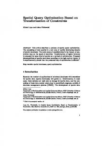
Furthermore, the data for the voyage corresponding to the cases shown in Fig. 3 are illustrated as a function of the ship positions in Fig. 4(a)-(d), respectively. These figures show the ship sailing speeds, wave heading angles, fuel consumption and parametric roll responses. It is obvious in Fig. 4(a) that the sailing speeds increase rapidly with decreased fuel consumption in Fig. 4(c) for the eastbound voyages due to the benefits of the Kuroshio. For westbound voyages, however, the sailing speeds with the corresponding fuel consumption appear the opposite patterns for avoiding the counter-flow currents near Japan Islands. Although the benefits of speed-up can be earned as a result of riding on the primary currents, it is significant in Fig. 4(d) that strong roll responses are inevitably induced by Typhoon Songda, especially for the eastbound voyages.
-120
(d)
#1 #2 #3 #4 #5 #6 #7 #8 #9 #10
35 30 25 20 15 10 5 0 120
140
160
180
-160
-140
-120
Longitude (deg.)
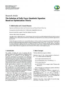
Figure 4. The comparisons of ship performance for different types of minimized fuel-consumption routes by observing (a) ship speeds; (b) wave heading angles; (c) fuel consumption; (d) parametric roll responses. Maximized safety routes Since Typhoon Songda generated on the east side of the Philippine Seas would cross the passage routes for both eastand west-bound voyages, it led to considerable responses of roll motion. Thus, a series of cases as shown in Table 4 were conducted by limiting different roll motion criteria from ship operations. Fig. 5 implies that the voyages of higher roll criteria principally follow the initial great circle route, whereas the lower ones show the great adaptability to the dynamic environments. The strategic routing of safe sailing is applied by altering the ship course or reducing the ship speed in the harsh weather conditions. Fig. 6(a)-(d) present the comparison of maximized safety routes by observing the histories of ship performances. The results indicate that the sailing speeds in Fig. 6(a) vary considerably with ship heading angles in Fig. 6(b) for the safety requirement of roll motion in Fig. 6(d). It is also found in Fig. (c) that the required fuel consumption increases evidently according to the voluntary speed loss. The increasing amount of fuel consumption and transit time is obtained with smaller roll criteria.
Longitude
Figure 3. The comparison of the minimized fuel-consumption routes by considering the speed criteria in 3DMI method. The color bars denote the distribution of current speeds. The arrow bars in the diagram indicate the current speeds and directions.
6 Downloaded From: http://proceedings.asmedigitalcollection.asme.org/ on 10/13/2014 Terms of Use: http://asme.org/terms
Copyright © 2013 by ASME
(b) wave heading angles; (c) fuel consumption; (d) parametric roll responses.
Table 4 The general descriptions of the voyage conditions. Case
V (kts) ∆t (hrs)
Description of voyages
Departure date
2011/05/28 00:00 2011/06/11 06:00 2011/05/28 00:00 2011/06/11 06:00 2011/05/28 00:00 2011/06/11 03:00 2011/05/28 00:00 2011/06/11 00:00 2011/05/28 00:00 2011/06/11 00:00 2011/05/28 00:00 2011/06/11 15:00 2011/05/28 00:00 2011/06/11 12:00 2011/05/28 00:00 2011/06/11 09:00 2011/05/28 00:00 2011/06/11 09:00 2011/05/28 00:00 2011/06/11 12:00
#11 #12 #13
22 3
East-bound
#14 #15 #16 #17 #18
22 3
West-bound
Max. roll criteria (deg.)
Arrival date
#19 #20
5 10 15 20 25 5 10 15 20 25
Latitude
#11 #12 #13 #14 #15 #16 #17 #18 #19 #20
Longitude
Figure 5. The comparison of the maximized safety routes by considering the roll responses in 3DMI method. The color bars denote the significant wave heights. The arrow bars in the diagram indicate the wind speeds and directions. (a)
Ship speed (m/s)
20
15
10
5
0 120
140
160
180
-160
-140
Longitude (deg.)
Fuel Consumption (ton)
13.5
12
11.5
11 120
140
160
180
-160
Longitude (deg.)
-140
-120
120 90 60 30
140
160
180
-160
-140
Longitude (deg.) #11 #12 #13 #14 1#5 #16 #17 #18 #19 #20
12.5
#11 #12 #13 #14 #15 #16 #17 #18 #19 #20
150
0 120
-120
(c)
13
(b)
180
Wave Heading Angle (deg.)
#11 #12 #13 #14 #15 #16 #17 #18 #19 #20
25
Parametric Roll Response (deg.)
25
-120
(d)
#11 #12 #13 #14 #15 #16 #17 #18 #19 #20
20
15
10
5
0 120
140
160
180
-160
-140
CONCLUSIONS In this paper, a proposed algorithm for ship routing optimization, 3DMI method, has been developed and verified. The database of seakeeping characteristics and added resistance for evaluating the ship routing were calculated based on the 6 DOF mathematical model of ship hydrodynamics. Since the dynamic environments change with time, which would modify the planned routes in the voyage correspondingly, the proposed 3DMI method employs the floating grid system to define the spatiotemporal layouts for ship routing optimization. In addition, the recursive forward algorithm is applied by considering the weight as the stage variable as well as the constraints of ship performance. Eventually, some of the results can be concluded and listed as follows: 1. The involuntary speed loss caused by ocean environments calculated by our mathematical model has great dependence on the ship performance. 2. The passage tracks for both east- and west-bound voyages show a flexible navigability according to the dynamic weather environments. 3. The passage tracks by comparing speed and roll criteria present an appreciable adaptability in dynamic environments, with regard to the fuel consumption and safety concern. 4. The voyage results indicate that the minimized fuelconsumption routes by means of 3DMI method have better performances on higher speed criteria than the lower ones. 5. In addition, the maximized safety routes in the 3DMI method increase the total transit time and fuel consumption as a result of voluntary speed loss. 6. The purpose of this paper is mainly focused on the capability and validity of the present 3DMI method. In the future, the work would attempt to add the cost functions to optimize the ship routing by adjusting different weights of control modes. ACKNOWLEDGMENTS The authors would like to express their thanks to the International Wave Dynamic Research Center, National ChengKung University, for a grant under Contract No. NSC 1022911-I-006-302. The partial support coming from China Ship Building Company (CSBC) is also greatly appreciated. The authors also acknowledge the financial support for this work provided by Research Center for Energy Technology and Strategy, NCKU.
-120
Longitude (deg.)
Figure 6. The comparisons of ship performance for different types of maximized safety routes by observing (a) ship speeds;
7 Downloaded From: http://proceedings.asmedigitalcollection.asme.org/ on 10/13/2014 Terms of Use: http://asme.org/terms
Copyright © 2013 by ASME
REFERENCES [1] BISHOP, J. M., Applied Oceanography. New York: Wiley, 1984. [2] Haddara, M. and Soares, C. G. (1999). "Wind loads on marine structures", MARINE STRUCTURES, Vol. 12, pp. 199-209. [3] Isherwood, R. M. (1972). "Wind resistance of merchant ships", Trans. Roy. Inst. Naval Architects, Vol. 114, pp. 327-338. [4] Lin, Y.-H. and Fang, M.-C., "Numerical Simulation of Ship Dynamics for Application in a Weather Routing System," in Proceedings of the 31st International Conference on Ocean, Offshore and Arctic Engineering, Rio de Janeiro, Brazil, 2012, pp. OMAE2012-83515. [5] Bijlsma, S. J., "On minimal-time ship routing," Ph.D., Royal Netherlands Meteorological Institute, Delft University of Technology, Delft, 1975. [6] Hagiwara, H. and Spaans, J. A. (1987). "Practical weather routing of sailassisted motor vessels", J Navig, Vol. 40, pp. 96-119. [7] Hagiwara, H., "Weather routing of (sail-assisted) motor vessels," Ph.D., Delft University of Technology, Delft, 1989. [8] Spaans, J. A. (1995). "New developments in ship weather routing", Navigation, Vol. 169, pp. 95-106. [9] Klompstra, M. B., Olsde, G. J., and Van Brunschot, P. K. G. M. (1992). "The isopone method in optimal control", Dyn Control, Vol. 2, pp. 281-301. [10] Calvert, S., Deakins, E., and Motte, R. (1991). "A Dynamic System for Fuel Optimization Trans-Ocean", Journal of Navigation, Vol. 44, pp. 233-265. [11] Dewit, C. (1988). "Practical Weather Routeing of SailAssisted Motor Vessels", Journal of Navigation, Vol. 41, pp. 134-134. [12] Shao, W., Zhou, P. L., and Thong, S. K. (2012). "Development of a novel forward dynamic programming method for weather routing", Journal of Marine Science and Technology, Vol. 17, pp. 239-251. [13] Avgouleas, K., "Optimal ship routing," Massachusetts Institute of Technology, Cambridge, 2008. [14] Tsujimoto, M. and Tanizawa, K. (2006). "Development of a weather adaptive navigation system considering ship performance in actual seas", 25th Int Conf on Offshore Mechanics and Arctic Engineering, Hamburg, Germany, pp. 4-9. [15] Padhy, C. P., Sen, D., and Bhaskaran, P. K. (2008). "Application of wave model for weather routing of ships in the North Indian Ocean", Natural Hazards, Vol. 44, pp. 373-385. [16] Takashima, K., Mezaoui, B., and Shoji, R. (2009). "On the fuel saving operation for coastal merchant ships using weather routing", International Journal on Marine Navigation and Safety of Sea Transportation, Vol. 3, pp. 401-406.
[17] [18]
[19]
[20] [21] [22]
[23] [24]
[25]
Bekker, J. F. and Schmid, J. P. (2006). "Planning the safe transit of a ship through a mapped minefield", J ORSSA, Vol. 22, pp. 1-18. Salvesen, N. (1974). "Second-order Steady-state Forces and Moments on Surface Ships in Oblique Regular Waves", Int. Symp. Dynamics of Marine Vehicles and Structures in Waves, University College London, pp. 212-226. Newman, J. N. (1974). "Second-order Slowly-varying Forces on Vessels in Irregular Waves", Int. Symp. Dynamics of Marine Vehicles and Structures in Waves, University College London, pp. 182-186. Fang, M. C. (1991). "Roll Reduction by Rudder Control for 2 Ships during Underway Replenishment", Journal of Ship Research, Vol. 35, pp. 141-150. Fang, M. C. and Chen, G. R. (2006). "On the nonlinear hydrodynamic forces for a ship advancing in waves", Ocean Engineering, Vol. 33, pp. 2119-2134. Fang, M. C., Wu, Y. C., Hu, D. K., and Lee, Z. Y. (2009). "The Prediction of the Added Resistance for the Trimaran Ship With Different Side Hull Arrangements in Waves", Journal of Ship Research, Vol. 53, pp. 227-235. HSVA (2002). "Performance and Analysis of Ship Powering Tests," Hamburg. Bonjean, F. and Lagerloef, G. S. E. (2002). "Diagnostic Model and Analysis of the Surface Currents in the Tropica Pacific Ocean", Journal of Physical Oceanography, Vol. 32, pp. 2938-2954. Fang, M.-C., Lin, Y.-H., and Wang, B.-J. (2012). "Applying the PD Controller on the Roll Reduction and Track Keeping for the Ship Advancing in Waves", Ocean Engineering, Vol. 54, pp. 13-25.
8 Downloaded From: http://proceedings.asmedigitalcollection.asme.org/ on 10/13/2014 Terms of Use: http://asme.org/terms
Copyright © 2013 by ASME