manipulator Justin, and a joint-torque control is used, where the collision ..... [8] I.D. Walker, âImpact configurations and measures for kinematically redundant ...
The skeleton algorithm for self-collision avoidance of a humanoid manipulator Agostino De Santis, Alin Albu–Sch¨affer, Christian Ott, Bruno Siciliano, and Gerd Hirzinger Abstract— For use in unstructured domains, highly redundant multi-arm robotic systems need both deliberative and reactive control schemes, in order to safely interact with the environment. The problem of collisions is crucial. A robust reactive algorithm, named the “skeleton algorithm”, is proposed for the real-time generation of self-collision avoidance motions, where only proprioceptive sensory data are needed. The algorithm is applied to the DLR humanoid manipulator Justin, and a joint-torque control is used, where the collision avoidance torques are summed to the desired torques corresponding to other tasks; experimental results are reported. Index Terms— Self-collision avoidance, Reactive control, Humanoid robots, Kinematics.
I. I NTRODUCTION Robots designed by mimicking upper-bodies of humans represent a good solution for two crucial skills in robotics in anthropic domains: dexterous manipulation and grasping. Moreover, their legible motions could improve the confidence of the users during physical Human-Robot Interaction (pHRI). The high number of degrees of freedom (DOFs) in such multi-arm structures needs complex task planning strategies, able to cope with the high dimensionality of the configuration space. In addition, reactive behaviours must be considered for use in anthropic domains [1]. In particular, the use in unstructured and time-varying environments implies the need for implementing real-time reactive strategies to cope with possible collisions. Such an approach should include features for: detection of possible colliding points [2], multiple-point control [3], modifications of the path as a reaction [4]. A novel humanoid two-arms-hands-torso system, named Justin, has been recently developed by DLR [5] and has been first shown at the Automatica Fair in Munich in May 2006. This robotic system (Fig. 1) is composed of a sensorized head, two DLR LWR-III arms [6] and an articulated torso with 3 active and 1 passive DOFs. The total number of DOFs (active and passive) of the robotic system is 18, plus 24 for the hands and 2 for the head. Only the arms and torso will be considered in this paper. One basic capability to be implemented for such a system is avoiding collisions during normal operation. Proprioception gives the position of the links for self-collision avoidance, while a good exteroceptive sensory system can This work is supported by the EU FP6 STReP PHRIENDS IST-045359. A. De Santis and B. Siciliano are with PRISMA Lab, DIS, Universit`a di Napoli Federico II, Italy {agodesa, siciliano}@unina.it A. Albu–Sch¨affer, C. Ott, and G. Hirzinger are with Institut f¨ur Robotik und Mechatronik, DLR, Oberpfaffenhofen, Germany {alin.albu-schaeffer, christian.ott,
gerd.hirzinger}@dlr.de
1-4244-1264-1/07/$25.00 ©2007 IEEE
Fig. 1.
The DLR humanoid manipulator Justin
extend this ability to the avoidance of collisions with external objects or people present in the operational space during interaction with the environment. Additional interesting issues for collision tactics are addressed in [7], [8]. Reactive collision avoidance has been widely treated in the robotics literature, and strategies have been suggested for computing the distances between possibly colliding parts, generating proper reactive movements, embedding the collision avoidance schemes in the control systems, etc. A complete framework has been proposed in [4], although the question remains on how to effectively compute the position of the control points and corresponding Jacobian matrices needed for control. In [2], for self-collision avoidance, humanoid robot arms are divided in finite elements located in fixed positions. From the control viewpoint, in [3] (where only kinematic control is addressed) and in [9], fixed control points for the generation of the reactive motion are used as well. The approach proposed in [9] and [10] considers the possibility of adopting elastic forces for the repulsion; moreover, the collision avoidance is fulfilled via perturbations of desired position, and inverse kinematics is then computed for completing the task. Discretization of the robot structure has been proposed for self-collision avoidance also related to humanoid leg [11] motions: polyhedral models have been adopted. Potential fields [12] are often adopted for reactive motion of robots modelled as particles under the effect of the field. One central problem with an articulated structure seems to be the difficulty to have a smooth repulsion force which acts on the whole manipulator with continuity. Such a force should be derived from a potential field through the evaluation of a suitable analytical distance and a corresponding
Jacobian-based torque action. The following desirable features should be implemented by a real-time self-collision avoidance algorithm for this kind of robotic system, namely: • considering the motion of any point of the robot for a possible reactive movement; • computing analytical distances in real time on a whole robot; • generating continuous repulsion forces for collision avoidance; • computing proper Jacobian matrices needed to evaluate corresponding nominal torques for the fulfillment of the collision avoidance; • arbitrarily shaping the potential functions used for protecting objects from collisions; • summing the reactive behaviour with any kind of current motion during interaction of the robot with the environment and people.
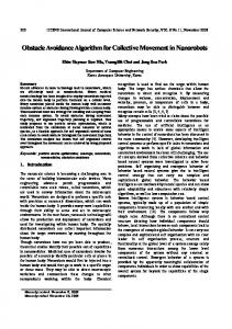
the segment ends located at the Cartesian positions of the joints are computed via simple direct kinematics. Notice that, due to the kinematics of the DLR LWR-III, the joint motion in the roll axes of the arms does not affect the position of the shoulder-elbow and elbow-wrist segments.
(a)
1.5
II. T HE SKELETON ALGORITHM
1 z
The “skeleton algorithm” can be considered as an extension of the Virtual End-Effectors approach [3] and is composed of these four steps: A. building a proper model of the robot, namely the skeleton, useful for analytical computation; B. finding the closest points to a possible collision along the skeleton, namely the collision points; C. generating repulsion forces; D. computing avoidance torque commands to be summed to the nominal torques for the controller. These steps are illustrated in the following.
R
0.5
L T
0 −0.20 x 0.2
−1
−0.5
0
y
0.5
1
(b) Fig. 2. For the DLR Justin (a), a skeleton can be found (b) by considering the axes of the arms and the spine of the torso. Segments are drawn between the Cartesian positions of some crucial joints
A. Building the skeleton In order to avoid collisions between the arms and the torso of a humanoid manipulator like Justin, one should consider all the points of the articulated structure which may collide (and injure people in pHRI). The problem of analyzing the whole volume of the parts of a manipulator is simplified by considering a skeleton of the structure (Fig. 2), and proper volumes surrounding this skeleton. The adopted geometrical model leads to using a very simple and fast computation rule for distance evaluation and modification of the trajectories for each point of the manipulator. In general, one could derive the skeleton automatically from a proper kinematic description, e.g. via a DenavitHartenberg table. However, it would be difficult to check automatically for which segments collision tests are not necessary. Therefore, it is more efficient, and also intuitive and straightforward, to set up the skeleton by hand, as done below. By focusing on Justin, it is easy to notice that such a skeleton can be composed by considering segments lying on the links of the arms and the torso. In this way, segments are built that “span” the whole kinematic structure of the manipulator. In Fig. 2 it is possible to observe ten segments in which the manipulator is decomposed, where
With an analytical technique, it is always possible to find the two closest points for each pair of segments of the structure. This information can be used in order to avoid a collision between these two points, e.g., by pushing the closest points whenever their distance becomes lower than a threshold. Spheres centered at these collision points can be considered as protective volumes, where repulsion has to start. Since the closest point can vary between the two ends of the segment, on the assumption of a fixed radius, the resulting protective volume will be a cylinder with two half spheres at both ends (see Fig. 3 (a)). With reference to the structure in Fig. 2, the volumes constructed around the torso point T and the points L and R for the left and the right arm, respectively, encompass the two segments from T to L and T to R which thus can be discarded, leading to consideration of a total of eight segments, i.e. two for the torso and three for each arm. B. Finding the collision points As anticipated above, the collision points move along the segments of the skeleton. Hence, the direct kinematics computation can be carried out in a parametric way for a generic point on each segment by simply replacing the
Fig. 3. Segments are protected by spheres centered in the collision points (a); a simple case of distance evaluation on a plane is reported (b)
Obviously, the technique is suitable for point-segment distance, with minor modifications. For later computation of the avoidance torques, it is necessary to compute the Jacobians associated with the collision points, i.e. the matrices J a,c and J b,c describing the differential mapping of p˙ a,c and p˙ b,c with the joint velocities q˙ of the whole structure, i.e. in compact form � � � � p˙ a,c J a,c ˙ q. (9) = p˙ b,c J b,c
link length in the homogeneous transformation relating two subsequent frames with the distance of the collision point from the origin of the previous frame. For each segment in which the structure is decomposed, the distance to all the other segments is calculated with a simple formula. Let pa and pb denote the positions of the generic points along the two segments, whose extremal points are pa1 , pa2 and pb1 , pb2 , respectively. One has:
It is worth noticing that the positions of pc,a and pc,b vary along the segments as the manipulator is moving. Hence, the associated Jacobians depend on the positions of the two pairs of segment ends, i.e. pa1 , pa2 , pb1 , pb2 , through (6). Thus, Eq. (9) can be rewritten as p˙ a1 J a1 � � p˙ a2 J a2 p˙ a,c (10) = Jt p˙ b1 = J t J b1 q˙ p˙ b,c J b2 p˙ b2
(a)
(b)
pa = pa1 + ta ua pb = pb1 + tb ub
(1) (2)
where the unit vectors ua and ub for the two segments are evaluated as follows: 1 (p − pa1 ) (3) ua = ||pa2 − pa1 || a2 1 (p − pb1 ) (4) ub = ||pb2 − pb1 || b2 and {ta ,tb } are scalar values, with ta ∈ {0, 1} ||pa2 − pa1 ||
tb ∈ {0, 1}. ||pb2 − pb1 ||
(pb1 − pa1 ) (ua − kub ) (1 − k 2 ) ta,c − uTa (pb1 − pa1 ) tb,c = k T
(5) (6)
with k = uTa ub .
(7)
It is understood that in the case the common normal does not intersect either of the two segments, i.e. ta /(||pa2 − pa1 ||) and tb /(||pb2 − pb1 ||) are both outside the interval {0,1}, then the distance between the closest extremal points becomes the minimum distance. This analytical approach leads to computing in real-time the collision points pa,c and pb,c for each pair of segments, and the related distance dmin = ||pa,c − pb,c ||.
whose terms can be computed by suitable differentiations of (2) through (6). C. Generating repulsion forces
The collision points pa,c and pb,c are found by computing the minimum distance between the two segments (see, e.g., Fig. 3 (b)). If the common normal between the lines of the two segments intersects either of them, then the values ta,c and tb,c for the parameters ta and tb can be computed as follows: ta,c =
where J a1 , J a2 , J b1 , J b2 obviously relate the joint velocities to the velocities of the two pairs of segment ends, and ∂pa,c ∂pa,c ∂pa,c ∂pa,c ∂pa1 ∂pa2 ∂pb1 ∂pb2 (11) Jt = ∂p ∂pb,c ∂pb,c ∂pb,c b,c ∂pa1 ∂pa2 ∂pb1 ∂pb2
(8)
Potential fields [12] or different optimization techniques can be used in order to generate the forces which will produce the self-collision avoidance motions. The two opposite forces acting on the two possibly colliding closest points pa,c and pb,c can be chosen as follows: h(dmin , d0 , dstart ) (pa,c − pb,c ) (12) dmin h(dmin , d0 , dstart ) = (pb,c − pa,c ) = −f a,c (13) dmin
f a,c = f b,c
where h is a nonlinear function of the arguments; dmin is the minimum distance computed as in (8), dstart is the starting distance where the force has to act: points farther than dstart are not subject to any repulsion. Moreover, d0 is the limit distance around the skeleton where a collision may occur: in the case of cylindrical links, d0 is the radius of the section of the link. Notice that h > 0 gives the amplitude of the force along the direction between the two collision points. It is not difficult to show that the above repulsion forces may be derived from a potential function ∞ h(δ, d0 , dstart )dδ (14) Uc = − dmin
by differentiation with respect to pa,c and pb,c , i.e. ∂U ∂pa,c
f b,c = −
∂U , ∂pb,c
(15)
leading to the expressions in (12),(13). In the case of a linear function
k (dstart + d0 − dmin ) if dmin < d0 + dstart h= 0 elsewhere (16) with k > 0, then the repulsion potential becomes
2 1 k (dstart + d0 − dmin ) if dmin < d0 + dstart Uc = 2 0 elsewhere (17) and the expressions of the repulsion forces follow simply. Further, in order to properly smoothen the manipulator motion upon the action of the repulsion forces, it is appropriate to add damping terms as follows: h(dmin , d0 , dstart ) (pa,c − pb,c ) − D a p˙ a,c (18) dmin h(dmin , d0 , dstart ) = (pb,c − pa,c ) − D b p˙ b,c (19) dmin
f a,c = f b,c
be exponential (dotted line) up to a given distance d1 , where it becomes linear.
where D a and D b are suitable positive definite matrices. It is worth pointing out, indeed, that multiple collision points on the same segment may need to be considered, whenever more segments are close to a possible collision. In such a case, one may fictitiously increase the values in the associated damping matrix for all those points but the closest one, so as to obtain one collision point per segment and thus one repulsion force. Notice also that, if damping is the same for the two segments, the forces have the same intensity in two opposite directions. The amplitude of the forces depends on design choices about the intensity of the repulsion between the arms, which affect the values of h and D a , D b . Inference systems can be helpful in order to dynamically modify the starting and limit distances and the shaping of the function h. In pHRI, the tuning of these parameters may depend on the part of the human body that is close to the manipulator. Choices of h are feasible, e.g. on the base of performance criteria like the Head Injury Criterion [1], where accelerations and velocities of the arms during the avoidance motions can be kept under a threshold in order to reduce the risk of injury for the body of a human user present in the workspace of the manipulator. If the focus is only on self-collision avoidance, such real-time inferences are not necessary. In Fig. (4), three choices for h are proposed, where the amplitude of the force can: • grow to infinity when the distance to a possibly colliding point approaches zero (hyperbolic function, solid line), or • be limited to a finite value (linear function as in (16), dashed line), provided that this value causes an avoidance motion faster than any other planned motion for the manipulator, or else
300 200 h
f a,c = −
•
100 0 0
Fig. 4.
0.1
0.2 dmin
0.3
Examples of varying amplitude for the repulsion force
The above generated repulsion forces will be used in the next section to compute avoidance torques at the manipulator joints via the Jacobian transpose. Nevertheless, it should be pointed out that suitable repulsion velocities could be likewise generated in lieu of repulsion forces. In such a case, these velocities could be used to compute avoidance joint velocities via a pseudo-inverse of the Jacobian [13]. This alternative solution has not been considered in the present work, since Justin is endowed with a torque controller which naturally allows summing the avoidance torques to those needed to execute a given task. D. Computing avoidance torques In view of the kineto-static duality for robotic systems with holonomic constraints, it is straightforward to compute the avoidance torques corresponding to the repulsion forces via the transpose of the Jacobians defined in (9), leading to � � f a,c � . (20) τ c = J Ta,c J Tb,c f b,c The use of the transpose of the Jacobian matrix for the evaluation of the avoidance torques does not allow a weighing of the joint involvement for the generation of the avoidance motions. A posture behaviour, e.g., can be enforced only via proper null-space projection [4]. Null-space techniques can be used to enforce master-slave behaviours for the two arms of the humanoid manipulator, e.g., the “master” arm can have the goal reaching as primary task, and the collision avoidance is in its null-space, while the “slave” arm must guarantee the collision avoidance (main task), while trying to follow a prescribed trajectory (the slave is not trajectory task-preserving, meaning that its main task is safety). This approach is suitable for pHRI: both arms are “slave” with respect to the position of the arm of a human operator. Since in the proposed approach the repulsion forces for a generic segment have been derived from a potential as in (15), the torque-based collision avoidance strategy fits within the passivity-based control framework developed at DLR for LWR-III [14, 15]. Within this framework, a joint torque feedback (using the torque signal sensed by
the torque sensor after the gear-box in each joint) is used to reducing the friction as well as the apparent inertia of the actuator. The input to the controller are the interaction torques τ i generated by, e.g., an impedance controller. By assuming a flexible joint model for the manipulator, the entire control structure can be put into the passivity framework, allowing also a Lyapunov-based convergence analysis [14, 15]. Such controller can incorporate the collision avoidance by just adding the proper avoidance torques to the interaction torques, i.e. f TCP � T τ i,c = τ i +τ c = J J Ta,c J Tb,c f a,c . (21) f b,c These torques need to be summed to the gravity (and inertial) torques generated by the motion controller. In (21), J is the Jacobian related to the positions of the end-effectors arms, while f TCP is the force generated by the impedance controller at the tool-center point (TCP). It should be clear that both the case of a single TCP —when only one arm is in contact with a human or the environment— and the case of two TCP’s can be considered with reference to (21). In order to show passivity of the controller including collision avoidance, the sum of all repulsion potentials
U (for all pairs of segments involved in Uc,tot = ci i possible collisions) has to be added to the storage function related to the manipulator and the controller, leading to
(a)
(b)
(c)
(d)
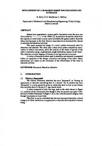
Fig. 5. Reactive movements of the manipulator in order to avoid a collision between the arms (first experiment)
them away, avoiding collisions. From the repulsion force, the corresponding torques have been computed as in the presented approach. Details related to two experiments are presented below.
0.275
˙ is the kinetic energy of the manipulator and Herein T (q, q) the virtual energy of the torque controlled actuator, U (q) contains the potential energy of the arm (gravity, elasticity) and of the controller and q describes the configuration of ˙ can be also used as the manipulator. The function V (q, q) a Lyapunov function for showing stability or asymptotic stability, depending on the choice of either a task-space or ˙ along a joint-space controller. The derivative of V (q, q) the system trajectories is namely �� � V˙ = −q˙ T D q˙ − p˙ Ta,c D a p˙ a,c + p˙ Tb,c D b p˙ b,c i
0.27
III. C ASE STUDIES Experiments have been performed in order to test the effectiveness of the skeleton algorithm for self-avoidance of Justin and, in general, for the LWR-III arm of the humanoid manipulator. Current trajectories have been acquired during manual guidance of the manipulator in torque control, where gravity has been suitably compensated. The manipulator has successfully avoided all collisions, and different potential functions have been tested. The critical distance dstart where the effect of the repulsion vanishes has been set to 30 cm. Damping has been considered in order to slow down the lightweight robot arms after repulsion forces moved
0.265 0.26 0.255 7.6
7.8
8
8.2
8.4
8.2
8.4
8.6
[s]
(a) 5
[Nm]
i
and contains all dissipative elements of the manipulator, the controller and the collision avoidance. Details about the control adopted for Justin are reported in [5].
[m]
˙ = T (q, q) ˙ + U (q) + Uc,tot . V (q, q)
0
−5 7.6
7.8
8 [s]
(b) Fig. 6. (a) distances of the two last segments of the left arm to the other segments of the manipulator during the second experiment; (b) corresponding avoidance torques
In Fig. 5, the reaction of the manipulator in real-time for collision avoidance during the first experiment can be observed. The user drives the right arm towards the left arm. The system finds the closest point between the segments of the skeleton and, when the distance becomes lower than the fixed threshold, the left forearm moves
away along a proper direction, with a repulsion force proportional to the distance and a proper damping in order to stop safely. Notice that the right arm is pushed by the same force, but the user is keeping the right wrist, compensating this force. The presence of torque sensors allows the simultaneous computation of proper torques for the manipulators, to cope with the force applied by the human user and the forces generated with the skeleton algorithm. The reactive motion of the manipulator can be better appreciated in the video www.prisma.unina.it/videos/PRISMAMov DLR Justin.wmv. From Fig. 6 it is possible to notice how, in the second experiment, the approach of the two arms results in a distance lower than the threshold of 30 cm, which implies the presence of two opposite repulsion forces. These forces cause the variation of the avoidance torques needed to push the closest points away. In this case, the torques, which are shown in Fig. 6 (b), depend only on the effect of the elbowwrist and wrist-hand segments, whose minimum distance from the rest of the structure are shown in Fig. 6 (a) for the left arm. It is possible to see how the reactive effect remains activated, since the users applies forces on the hands, keeping them closer than dstart . A good point to notice is the symmetry of the structure, leading to cancellation of equivalent movements in different directions caused by the double repulsion of the pairs of collision points which are considered by the control system. For instance, if the two hands are going to collide, the involvement of the joints of the torso is significantly reduced with respect to the arms’ joints. Different repulsion functions and different values in the damping matrix have been adopted, leading to faster or slower reaction of the manipulator when approaching the starting distance for the repulsion effects, but the results are not reported here for brevity. The shape of such a function is important for studying the initial distance and velocity which are to be adopted for different avoidance tasks, from self-avoidance to object avoidance, up to human body avoidance. IV. C ONCLUSION AND FUTURE WORK The skeleton algorithm has been presented in this work to avoid real-time collisions of a humanoid manipulator interacting with humans. The robotic structure is divided in segments, so that arbitrary points can be selected and controlled, e.g., for reactive motion. The collision points on such segments are found and suitable repulsion forces are generated, which are then transformed into avoidance torques to be summed to the interaction torques for a given contact task. The algorithm has been successfully tested in two experiments on the humanoid manipulator Justin, showing the effectiveness of the approach in practical case studies where a human is interacting with both arms of the manipulator. As an alternative to the presented technique, the skeleton algorithm could be applied also for a velocity control based implementation, i.e. by generating repulsion velocities for
the collision points, and thus computing the joint velocities via proper inverse kinematics [16]. As for future work, tracking of interacting people, e.g., via markers in elbow and wrist [17] can be used for building a robust skeleton-based model for human avoidance. R EFERENCES [1] R. Alami, A. Albu-Schaeffer, A. Bicchi, R. Bischoff, R. Chatila, A. De Luca, A. De Santis, G. Giralt, G. Hirzinger, V. Lippiello, R. Mattone, S. Sen, B. Siciliano, G. Tonietti, L. Villani “Safe and dependable physical human-robot interaction in anthropic domains: state of the art and challenges”, Workshop on Physical Human-Robot Interaction, 2006 IEEE/RSJ Conference on Intelligent Robots and Systems, Beijing, PRC, 2006. [2] F. Seto, K. Kosuge, R. Suda, H. Hirata, “Real-time control of selfcollision avoidance for robot using RoBE”, 2003 IEEE International Conference on Humanoid Robots, Karslruhe–M¨unchen, D, 2003. [3] A. De Santis, P. Pierro, B. Siciliano, “The virtual end-effectors approach for human-robot interaction”, 10th International Symposium on Advances in Robot Kinematics, Ljubljana, SLO, 2006. [4] O. Brock, O. Khatib, “Elastic strips: a framework for motion generation in human environments”, International Journal of Robotics Research, vol. 21, pp. 1031–1052, 2002. [5] C. Ott, O. Eiberger, W. Friedl, B. B¨auml, U. Hillenbrand, C. Borst, A. Albu-Sch¨affer, B. Brunner, H. Hirschm¨uller, S. Kiehl¨ofer, R. Konietschke, M. Suppa, T. Wimb¨ock, F. Zacharias, G. Hirzinger, “A humanoid two-arm system for dexterous manipulation”, 2006 IEEE International Conference on Humanoid Robots, Genova, I, 2006. [6] G. Hirzinger, A. Albu-Schaeffer, M. Hahnle, I. Schaefer, N. Sporer, “On a new generation of torque controlled light-weight robots”, 2001 IEEE International Conference of Robotics and Automation, Seoul, K, 2001. [7] A. De Luca, A. Albu-Schaeffer, S. Haddadin, G. Hirzinger, “Collision detection and safe reaction with the DLR-III lightweight manipulator arm”, 2006 IEEE/RSJ International Conference on Intelligent Robots and Systems, Beijing, PRC, 2006. [8] I.D. Walker, “Impact configurations and measures for kinematically redundant and multiple armed robot systems”, IEEE Transactions on Robotics and Automation, vol. 10, pp. 670–683, 1994. [9] B. Bon, H. Seraji, “On-line collision avoidance for the Ranger telerobotic flight experiment,” 1996 IEEE International Conference on Robotics and Automation, Minneapolis, MN, 1996. [10] H. Seraji, B. Bon, R. Steele, “Real-time collision avoidance for 7DOF arms”, 1997 IEEE/RSJ International Conference on Intelligent Robots and Systems, Grenoble, F, 1997. [11] J. Kuffner, K. Nishiwaki, S. Kagami, Y. Kuniyoshi, M. Inaba, H. Inoue, “Self-collision detection and prevention for humanoid robots”, 2002 IEEE International Conference on Robotics and Automation, Washington, DC, 2002. [12] O. Khatib, “Real-time obstacle avoidance for robot manipulators and mobile robots”, International Journal of Robotics Research, vol. 5(1), pp. 90–98, 1986. [13] L. Sciavicco, B. Siciliano, Modelling and Control of Robot Manipulators, (2nd Ed.), Springer-Verlag, London, UK, 2000. [14] C. Ott, A. Albu-Sch¨affer, G. Hirzinger, “A passivity based Cartesian impedance controller for flexible joint robots — Part I: Torque feedback and gravity compensation”, 2004 IEEE International Conference on Robotics and Automation, New Orleans, LA, 2004. [15] A. Albu-Sch¨affer, C. Ott, G. Hirzinger, “A passivity based Cartesian impedance controller for flexible joint robots — Part II: Full state feedback, impedance design and experiments, 2004 IEEE International Conference on Robotics and Automation, New Orleans, LA, 2004. [16] A. De Santis and B. Siciliano, “Reactive collision avoidance for safer human–robot interaction”, 5th IARP/IEEE RAS/EURON Workshop on Technical Challenges for Dependable Robots in Human Environments, Roma, I, 2007. [17] V. Caggiano, A. De Santis, B. Siciliano, A. Chianese, “A biomimetic approach to mobility distribution for a human-like redundant arm”, 1st IEEE RAS/EMBS International Conference on Biomedical Robotics and Biomechatronics, Pisa, I, 2006.