590
IEEE TRANSACTIONS ON MAGNETICS, VOL. 44, NO. 5, MAY 2008
Three- and Two-Dimensional Finite-Element Computation of Inrush Current and Short-Circuit Electromagnetic Forces on Windings of a Three-Phase Core-Type Power Transformer Jawad Faiz, Bashir Mahdi Ebrahimi, and Tahere Noori Center of Excellence on Applied Electromagnetic Systems, Department of Electrical and Computer Engineering, University of Tehran, Tehran, Iran Although short-circuit current is frequently considered the major design fundamental for power transformers, experience with transformer failures shows that inrush currents that occur when transformers are energized can also cause serious damage. To investigate the resultant forces due to energizing power transformer windings, we modeled a three-phase, three-legged 66/11 kV, 40 MVA power transformer in two and three dimensions. We calculated electromechanical forces for short-circuit cases and also for inrush current through the windings, using the finite-element method. The results show that the forces exerted on the windings due to inrush current in many regions are larger than those due to short-circuit currents. Since the inrush current appears more frequently with a much longer duration compared to a short-current event, its harmful effects are worse than those of the short-circuit case. Index Terms—Electromagnetic forces, finite-element method, inrush current, power transformer, short-circuit.
I. INTRODUCTION
D
ESIGNING power transformers, as a major and key apparatus of electric power systems, is very important, because their breakdown results in costly repair or replacement. This may lead to temporary loss of electrical power at very high cost [1]. One of the threatening factors for power transformers is inrush current at the energizing time, which has particularly undesirable affects on its windings and may gradually ruin the transformer. In the design of power transformers, short-circuit conditions are considered the worst conditions to determine the dimensions. In many cases, the amplitude of the inrush current can be equal to the short-circuit current [1], but since inrush current lasts longer in the system its repetition can seriously damage the windings. Perhaps short-circuit and inrush current seem similar, but they are completely different from the core magnetizing point of view. In the short-circuit case, a large current passes the primary and also secondary, while inrush current passes only the primary winding and secondary winding is normally open-circuit at no-load [2]. On the other hand, magnetizing current in the steady-state operation is only 1% to 2% of the rated current, while inrush current could tend to 10 to 20 times the rated current [3]. There are many papers concerning the nature of the inrush current in power transformers [3]–[5], but radial and axial electromechanical forces exerted on the windings of the transformer are rarely studied [1], [2]. In [2], mechanical forces within the windings built up under inrush current of a single-phase transformer are evaluated using the Hopefield neural network (HNN) energy minimization technique, and it has been shown that almost always-positive radial forces build up in the LV winding during an inrush current when HV winding
Digital Object Identifier 10.1109/TMAG.2008.917819 Color versions of one or more of the figures in this paper are available online at http://ieeexplore.ieee.org.
is left open, while the same winding may be subject to a negative radial force during a short circuit state. It has been also observed that the axial forces acting on the LV winding are less in the case of a short circuit compared to its corresponding values on inrush current state. In [1], the forces have been calculated using the finite-element method (FEM) for both inrush current and short-circuit current cases and the results are compared; however, the asymmetry of the inrush current was ignored and it was shown that for inrush current peaks of 70%, the rated short-circuit current local forces are on the same order of magnitude as those at short-circuit. It also shows that the axial force distribution along the tap-changing coils is approximately 20% higher at inrush current than in the short-circuit case. To avoid complexity of the simulation model, the actual three-dimensional (3-D) geometry of a three-legged power transformer was simplified into a one-phase, two-dimensional (2-D) equivalent axial symmetry geometry. Simulation results obtained in the above-mentioned 3-D and 2-D models were close. In [6], it has been shown that in the proposed transformer the exerted forces under unbalanced magnetomotive forces (MMFs) on the outer winding can be 2 to 10 times the forces in the short-circuit case. The buckling strength analysis of transformer windings subjected to electromagnetic force under short-circuit has been dealt with in [7]. Based on the expressions of transient three-phase short-circuit current, the formulas of radial and axial electromagnetic forces acting on the transformer windings have been derived [8]. The fundamental assumptions in [8] include two-dimensional (2-D) field, neglecting saturation and eddy current, simplified transformer equivalent circuit, and equal ampere-turns of primary and secondary. In [8], it has been shown that the amplitudes of the axial forces in the yoke have considerable differences with that of the outer points. The improved - method has been employed in [9] to estimate the short-circuit electromagnetic forces acting on the large transformer windings. A 3-D analysis of the magnetic field and electromagnetic forces due to the short circuit current has been done using - method [8]. It has been shown that the
0018-9464/$25.00 © 2008 IEEE
FAIZ et al.: 3- AND 2-D FINITE-ELEMENT COMPUTATION OF INRUSH CURRENT AND SHORT-CIRCUIT ELECTROMAGNETIC FORCES
distribution of the axial force density in both terminals of the windings in the direction of height is larger than that of the middle point. The radial components of the flux density and nonuniform distribution of ampere-turns lead to the nonidentical forces distribution curve in two windings. Also, density of the axial forces under the core yoke outer points is different. Different techniques based on the theory of images and the FEM enabling to calculate the static electromagnetic forces on the winding of power transformers have been compared in [10]. The electromagnetic forces acting in a power transformer under short-circuit in the windings have been determined in [11]. Although nonlinearity of the core material has been taken into account, the skin effect, eddy current, and magnetic field outside the transformer have been ignored. The stationary magnetic field has been studied at the moment when the current is maximal. It has been shown that the axial components are expressed the most at the end of the windings and displacement of the windings in the axial direction, while the radial component of the forces produces a hoop stress in the other winding and compressive stress in the inner winding. In [12], FEM has been used to evaluate the forces exerted on the coils of a single-phase shell-type transformer. It has been shown that the skin effect and proximity effect have no significant effect on the total force. It has been shown that the amplitudes of the axial forces in the yoke have a considerable difference with that of the outer points. It has been confirmed that a 3-D analysis is necessary to compute the end forces and examine asymmetries outside the window that are not possible with 2-D analysis. A comprehensive analysis of a split-winding transformer has been reported in [13] to assess its short-circuit performance under preset and post-set short-circuit test conditions. The axial and radial force has been computed using nonlinear transient field-circuit coupled formulation. The 2-D asymmetric nonlinear transient FE model has been developed to investigate transient axial and radial forces in the windings of split-winding transformers; it has been verified with the 3-D model and also shown that there is a considerable rise in the axial forces when one winding is short circuited as compared with the case when both windings are short-circuited. In [14], the short-circuit conditions in a large power transformer have been analyzed and it has been concluded that the local axial force in both terminals of the winding (with a larger radial components) is much larger than that of the middle parts of the winding. The goal of the present paper is the calculation and investigation of the forces under inrush current and short circuit current and their comparison taking into account the asymmetry of phase current in the inrush current state. A three-phase threelegged power transformer is modeled in 2-D and 3-D and different developed forces under inrush current and short-circuit are calculated by FEM. In addition, a one-phase, 2-D equivalent axial symmetric geometry model reported in [1] is also simulated. The simulation method and the results are presented and developed forces under inrush current and short-circuit cases are compared in 2-D and 3-D cases. II. FINITE-ELEMENT MODELING OF TRANSFORMER A three-phase, three-legged, core-type power transformer is modeled by the Vector Field 2-D and 3-D FE packages. Dimen-
591
Fig. 1. Dimensions of the proposed transformer (all values in mm).
TABLE I SPECIFICATIONS AND DIMENSIONS OF PROPOSED THREE-PHASE THREE-LEGGED CORE-TYPE TRANSFORMER
sions and specifications of the proposed transformer are presented in Fig. 1 and Table I. For modeling the transformer, the following have been considered. 1) In 3-D modeling, the core with real dimensions and laminated exactly similar to the actual core of transformer (to exclude the eddy current effects in a real core) is simulated. In the 2-D modeling of three legs, core cross section is taken to be square shape, and in the single leg modeling the core is assumed similar with that reported in [1]. 2) To simplify the 2-D modeling, cross sections of the windings are considered and the windings depths are not taken into account. However, this simplification reflects the inherent characteristic of the 2-D modeling which causes a small error. Unit length in z-direction is considered for the force calculations by 2-D model; to obtain the actual force the calculated force is multiplied by the length of the transformer in z-direction.
592
IEEE TRANSACTIONS ON MAGNETICS, VOL. 44, NO. 5, MAY 2008
Fig. 2. Magnetization characteristic of transformer core.
3) Although the peak current does not always develop the maximum force, the transformer tap is placed on the first step in order to pass the maximum current through the windings. 4) The magnetization characteristic of the core material provided by the manufacturer is used (see Fig. 2). 5) Fig. 3 shows the scheme of the modeled transformer in which the cross section of the core has been considered square-shaped. Fig. 3(b) presents the zoomed view of the top right of transformer. Since the core diameter has significant influence upon the force calculations, Fig. 3(b), presenting the depth of the transformer core, has been given individually. If the third dimension of the transformer (core diameter) is not modeled, the force of unity length is calculated and multiplied by the length of the transformer. In the 2-D, three-phase, and 3-D models, asymmetry of the currents of the phases at the energized transformer are taken into account. In the 2-D model of single leg, where only the middle leg is simulated, it is assumed that the maximum current passes the middle phase at the switch-on time. III. ANALYSIS METHOD Vector field software does magnetic field analysis by solution of the Maxwell equations [15]. The local force density, , in the winding is equal to the vector product of local current density, , in the winding and the local magnetic flux density, , as given by (1) Since the current density assigned to the windings is obtained from the amplitude of the first peak of the inrush current, it has a constant value, consequently relationship between the flux density and force is assumed linear. So, for calculation of forces and their distributions only determination of the flux density distribution is sufficed [1]. Since the windings are assumed to be cylindrical, only azimuthally component of the current is considered. For magnetic field analysis around windings at the transformer energizing time, knowing the amplitude of the current
Fig. 3. Scheme of the modeled transformer: (a) 3-D, (b) zoomed of the top right of transformer, (c) meshed three-leg 2-D, and (d) meshed single-leg, 2-D with modified core.
passing through the windings is necessary. Since phase currents in the transient conditions of the inrush current is not symmetrical, similar to the normal case, current of three phases must be separately calculated. Current of any phase of energizing transformer is obtained by transient analysis of the 2-D three-legged model. IV. FLUX AND INRUSH CURRENT ESTIMATION In the analysis of a transformer using the time-stepping finite-element method (TSFEM), the voltage applied to the terminal of the transformer is considered as the required input value and primary phase current is evaluated as the unknown
FAIZ et al.: 3- AND 2-D FINITE-ELEMENT COMPUTATION OF INRUSH CURRENT AND SHORT-CIRCUIT ELECTROMAGNETIC FORCES
593
By substituting in (4) (6) (7) Since the right-hand side of (7) is sinusoidal, the response of the equation has an exponential transient component, and a sinusoidal steady-state component, , and (8) (9)
Fig. 4. Flux distribution within transformer.
value. The transient equations of the external circuit showing the electric supplies and circuit elements are combined with the field equations in TSFEM. Solution of this system of equations can provide the primary phase current as a principle and required variable. An equation that relates the FE equations expressing electromagnetic of the transformer with electrical circuit equations is as follows:
(10) is the initial phase of . At the no-load condition, flux almost 90 delay, therefore
(11) is the maximum amplitude of the steady-state flux. At , thus flux is equal to the residual flux
(2)
where is the electrical angular frequency which is equal to that of the input voltage. Flux distribution in 2-D within the transformer is presented in Fig. 4. V. JUSTIFICATION OF FLUX AND INRUSH CURRENT COMPUTATION RESULTS Voltage equation in the primary winding is as follows:
,
(12) (13)
and are the magnetic potential vector and current where , , , and are the coeffithat must be determined. is the vector related to the input voltage. cients matrices, and Fig. 4 shows the inrush current of the full-load transformer. The peak value of inrush current is equal to 10.5 kA. The system approaches its steady-state after a very short time, and therefore and are obtained as follows: (3)
has
(14)
(15) Referring to (15), the worst case occurs when the transformer is energizing and voltage is at and has maximum negative amplitude. So, the three-phase 2-D modeled transformer has been energized at zero angle of the voltage and the maximum negative residual flux. Fig. 5 presents the inrush current in the HV windings in which asymmetry of the three phase currents is obvious. As shown in the figures, the inrush current has been damped after 300 ms and the primary winding current tend to its rated value. At the first instant, the maximum current passes two phases of the HV winding, the amplitudes of the obtained currents were applied to the simulated models.
(4) VI. ELECTROMAGNETIC FORCE CALCULATIONS is the primary winding turn number, is the total where flux consisting of the steady-state and residual fluxes, is the primary winding resistance, is the primary winding current, and is the voltage initial phase. In the steady-state, the total , which depends on the magnetiflux depends on , zation characteristic of the core. If transformer operates within the linear region of the magnetization characteristic (above the knee of the curve), then (5)
Distribution of the magnetic flux density is calculated from the magnetic potential vector as follows: (16) It is noted that has been already computed in Section IV. the distribution of the forces along the Therefore, having height of the windings in the axial direction ( ) (2-D models) and in the direction (3-D model) is determined. The height of winding is divided into 1000 parts (in both 2-D and 3-D model)
594
IEEE TRANSACTIONS ON MAGNETICS, VOL. 44, NO. 5, MAY 2008
Fig. 6. LV winding where flux density is calculated along lines 1 and 2.
and the other regions are different, for example, Fig. 7 shows the radial and axial flux density in the inner surface of the LV winding along lines 1 and 2 in Fig. 6. So the windings are divided into 12 segments in azimuthally direction to include these variations, and forces are obtained in 120 000 parts. The height of these elements is identical, thus (17)
(18) Consequently, the resulting axial force at the coil’s end is (19) where is the radius of any layer of the winding, is the is the flux density in the segment th of th winding, and , for 2-D models winding thickness. and for 3-D model . To check the model accuracy, the number of the nodes and elements in the FE computations are changed and the forces on the middle leg LV winding within 2-D three-legged model are determined. In the force calculation the end points and inner and outer surfaces of the windings are important, and the mesh is changed by varying the number of elements in these points. The results have been summarized in Table II. It is noted that a similar procedure is used for force calculation in the case of short circuit. VII. COMPARISON OF 2-D AND 3-D MODELS
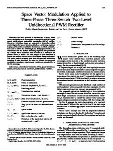
Fig. 5. Inrush current in the HV winding: (a) phase a, (b) phase b, and (c) phase c.
and the force for each part is obtained. The flux density distribution in the windings indicates that it varies along the coil thickness. Therefore, evaluation of force on different layers of the winding is necessary. At this end, in 3-D model the windings are divided into 10 parts along their radial. In the 3-D model, the flux density in the regions of the windings under the yoke
Figs. 8–11 show the axial and radial forces developed by the inrush current in the HV and LV winding of 3-D and 2-D threelegged and 2-D single-legged models. These forces have been obtained in the middle leg and along the height of windings. These figures show that the forces calculated in 2-D models are significantly different from those obtained from the 3-D model. Fig. 8 presents the axial force on LV winding in which the maximum axial forces on HV winding calculated by both 2-D models are almost the same but they differ about 40% from that calculated in 3-D model. Fig. 9 shows that the maximum axial forces calculated in three-phase, 2-D and one-phase, 2-D models differ 36% and 45% from that obtained by 3-D model. Fig. 10 shows that the maximum radial forces on LV winding
FAIZ et al.: 3- AND 2-D FINITE-ELEMENT COMPUTATION OF INRUSH CURRENT AND SHORT-CIRCUIT ELECTROMAGNETIC FORCES
595
Fig. 9. Axial force on HV winding in three models.
Fig. 7. Normalized values of flux density applied on the inner surface of LV winding along lines 1 and 2: (a) radial and (b) axial.
TABLE II FORCES ON LV WINDING IN THE MIDDLE LEG FOR DIFFERENT MESH NUMBERS—TWO-DIMENSIONAL [FIG. 3(c)]
Fig. 10. Radial force on LV winding in three models.
Fig. 11. Radial force on HV winding in three models.
Fig. 8. Axial force on LV winding in three models.
in three-phase and one-phase 2-D models differ about 10% and 80% from the force calculated in 3-D model. Fig. 10 shows even a larger difference between the models. The radial force calculated by three-phase and one-phase 2-D models differ about
64% and 68% from that obtained by 3-D model. These figures show that both 2-D models have an insufficient accuracy in forces calculation, particularly for the radial forces. In the onephase, 2-D model only one phase has been modeled, meaning that the axisymmetry of current has been ignored and this is the major reason for the low accuracy in this case. Although in three-phase, 2-D model, the shape of the coils has been taken into account while calculating the forces, this has been ignored in the flux density and forces calculations on LV winding.
596
IEEE TRANSACTIONS ON MAGNETICS, VOL. 44, NO. 5, MAY 2008
Fig. 12. Axial forces due to inrush current and short circuit current applied on LV winding.
Fig. 13. Axial forces due to inrush current and short circuit current applied on HV winding.
Since the force obtained in 2-D and precise 3-D model differ considerably, and on the other hand, the difference between the flux density under and outside of the core yoke is not visible in 2-D modeling, in order to investigate the forces developed by the inrush current in power transformer precisely and their comparison with the forces obtained for short circuit, 3-D model is used. Figs. 12–15 show 3-D model analysis of the forces in the transformer windings in the short circuit and inrush current modes. Figs. 12 and 13 indicate that the axial forces applied to the LV and HV windings when inrush current is about 45% and 36% larger than the corresponding forces in short circuit case. Figs. 14 and 15 show the distribution of radial forces in LV and HV windings. As seen the radial force on the LV winding in short circuit case is about 40% larger than the corresponding force in inrush current condition, while the maximum radial force on HV winding in short circuit case is about 1/3 that of inrush current. VIII. CONCLUSION In order to examine the radial and axial electromechanical forces developed by the inrush current and short-circuit, 2-D and 3-D FEM models were presented. The results show that the forces obtained from 2-D models are considerably different
Fig. 14. Radial forces on LV winding due to inrush and short circuit currents.
Fig. 15. Radial forces on HV winding due to inrush and short circuit currents.
than those obtained by precise 3-D models. In the 3-D model, it was proved that the axial forces due to inrush current are always larger than those obtained for short circuit current. It has been also shown that the radial force on the LV winding in inrush current condition is 40% less than that of short circuit while the inrush current radial force applied on HV winding is about three times the corresponding force of short circuit condition. The maximum difference between the inrush current and short circuit current from electromechanical forces viewpoint, is the unbalanced excitation and consequently developing axial forces with high amplitude that put the windings under stress in the energizing period which is longer that the short circuit case. REFERENCES [1] M. Steurer and K. Fröhlich, “The impact of inrush currents on the mechanical stress of high voltage power transformer coils,” IEEE Trans. Power Del., vol. 17, no. 1, pp. 155–160, Jan. 2002. [2] A. A. Adly, “Computation of inrush current forces on transformer windings,” IEEE Trans. Magn., vol. 37, no. 4, pp. 2855–2857, Jul. 2001. [3] J. J. Rico, E. Acha, and M. Madrigal, “The study of inrush current phenomenon using operational matrices,” IEEE Trans. Power Del., vol. 16, no. 2, pp. 231–237, Apr. 2001. [4] P. C. Y. Ling and A. Basak, “Investigation of magnetizing inrush current in a single-phase transformer,” IEEE Trans. Magn., vol. 24, no. 6, pp. 3217–3222, Nov. 1988. [5] J. Takehara, M. Kitagawa, T. Nakata, and N. Takahashi, “Finite element analysis of inrush currents in three-phase transformers,” IEEE Trans. Magn., vol. M-23, no. 5, pp. 2647–2649, Sep. 1987.
FAIZ et al.: 3- AND 2-D FINITE-ELEMENT COMPUTATION OF INRUSH CURRENT AND SHORT-CIRCUIT ELECTROMAGNETIC FORCES
[6] C. M. Arturi, “Force calculation in transformer windings under unbalanced mmfs by a non-linear finite element code,” IEEE Trans. Magn., vol. 28, no. 2, pp. 1363–1366, Mar. 1992. [7] H. Kojim, H. Miuata, S. Shida, and K. Okuyama, “Buckling strength analysis of large power transformer windings subjected to electromagnetic force under short circuit,” IEEE Trans. Power App. Syst., vol. PAS-99, no. 3, pp. 1288–1297, May 1980. [8] T. Y. Qiu, Q. J. Qiu, and X. Z. Hong, “Numerical calculation of short circuit electromagnetic force on the transformer winding,” IEEE Trans. Magn., vol. 26, no. 2, pp. 1039–1041, Mar. 1990. [9] T. Renyuan, L. Yan, L. Dake, and T. Lijian, “Numerical calculation of 3D transient eddy current field and short circuit electromagnetic force in large transformers,” IEEE Trans. Magn., vol. 28, no. 2, pp. 1418–1421, Mar. 1992. [10] A. Kladas, M. P. Papadoppoulos, and J. A. Tegopoulos, “Leakage flux and force calculation on power transformer windings under short-circuit: 2D and 3D models based on the theory of images and the finite element method compared to measurements,” IEEE Trans. Magn., vol. 30, no. 5, pp. 3487–3490, Sep. 1994. [11] K. Najdenkoski and D. Manov, “Electromagnetic forces calculation on power transformer windings under short circuit,” Int. J. Comput. Math. Electr. Electron. Eng., vol. 17, no. 1/2/3, pp. 374–377, 1998. [12] S. Salon, B. LaMattina, and K. Sivasubramaniam, “Comparison of assumptions in computation of short circuit forces in transformers,” IEEE Trans. Magn., vol. 36, no. 5, pp. 3521–3523, Sep. 2000. [13] G. B. Kumbhar and S. V. Kulkarni, “Analysis of short-circuit performance of split-winding transformer using coupled field-circuit approach,” IEEE Trans. Power Del., vol. 22, no. 2, pp. 936–943, Apr. 2007. [14] S. L. Ho, Y. Li, H. C. Wong, S. H. Wang, and R. Y. Tang, “Numerical simulation of transient force and eddy current loss in a 720-MVA power transformer,” IEEE Trans. Magn., vol. 40, no. 2, pp. 687–690, Mar. 2004. [15] Vector Field Software Documentation, 2005. [16] W. Xu, S. G. Abdulsalam, Y. Cui, and X. Liu, “A sequential phase energization technique for transformer inrush current reduction,” IEEE Trans. Power Del., vol. 20, no. 2, pt. 1, pp. 950–957, Apr. 2005.
Manuscript received September 20, 2006; revised January 26, 2008. Corresponding author: J. Faiz (e-mail:
[email protected]).
597
Jawad Faiz (M’90–SM’93) received the Ph.D. degree in electrical engineering from the University of Newcastle upon Tyne, U.K., in 1988. He is a Professor and the Director of the Center of Excellence on Applied Electromagnetic Systems at the Department of Electrical and Computer Engineering, University of Tehran, Tehran, Iran. His teaching and research interests are switched reluctance and VR motors design, design and modeling of electrical machines and drives. Dr. Faiz is a member of the Iran Academy of Sciences.
Bashir Mahdi Ebrahimi received the B.Sc. and M.Sc. degrees in electrical power engineering from the University of Tabriz, Tabriz, Iran, in 2001 and 2006, respectively. He is working toward the Ph.D. degree in the Department of Electrical and Computer Engineering, University of Tehran, Tehran, Iran. His research interests are electrical machines modeling and fault diagnosis.
Tahere Noori received the B.Sc. degree in electrical engineering from Iran University of Science and Technology, Tehran, Iran, in 2003 and the M.Sc. degree in electrical power engineering from the Department of Electrical and Computer Engineering, University of Tehran, Tehran, Iran, in 2006. She is now with Moshaver-Niro Company working as a consultant engineer in Tehran, Iran.