Touch-and-Connect: A Connection Request Framework for Ad-hoc Networks and the Pervasive Computing Environment. Yohei Iwasaki. â . Nobuo Kawaguchi. â¡.
Touch-and-Connect: A Connection Request Framework for Ad-hoc Networks and the Pervasive Computing Environment Yohei Iwasaki † Nobuo Kawaguchi ‡ Yasuyoshi Inagaki † † Graduate School of Engineering, Nagoya University ‡ Information Technology Center, Nagoya University {iwasaki,kawaguti}@cogma.org Abstract The spread of short distance wireless communication technology is making it possible for various information appliances to communicate through a network. However, to connect and to use them, we must generally perform complicated setup operations such as setting addresses or names. In this paper, we propose a user-friendly connecting management framework called “Touch-and-Connect”. With this method, we can connect any networked devices only by touching them. This system is designed so that it can work without a server, and even if many individuals operate it independently, no incorrect connections occur. And we have exemplified the usefulness of this framework with subject experiments.
1. Introduction With advances in hardware technology, every device will include a smart computer and be increasingly miniaturized. Thus we will live in a pervasive computing environment, surrounded by information appliances of many sorts. Weiser[1] presents a vision of an invisible computer system that need not impinge on the user’s awareness, yet that renders assistance spontaneously. However, as yet it is difficult for the computer system to recognize users’ various intentions without any input from users. So it is very important that users can communicate their desires to the system intuitively, without paying conscious attention to the complexities of the computer. The spread of technologies such as Bluetooth and wireless Ethernet is making it possible for various devices to communicate via wireless connections. These devices provide a rich array of services for users when they communicate, interact, and become integrated through a network. However, in order to connect and integrate these devices, we are generally required to perform complicated setup op-
erations. For example, when a user wants to connect two small wireless networked devices, the user may have to select an address or name of the destination device in a small display. This is cumbersome, especially if there are numerous devices in the network. In this paper, we propose the Touch-and-Connect Framework, which enables users to connect various devices by just touching them, instead of stepping through complicated setup operations. In order to work in an ad-hoc network environment, this framework is designed so that it can work without a server. Because the pervasive computing environment involves many devices and users, this framework includes a lock mechanism that prevents incorrect connections caused by the independent operations of users. In Section 2, we propose the Touch-and-Connect Framework, which is a user-friendly connecting management framework for ad-hoc networks and the pervasive computing environment. In Section 3, we discuss the prototype system of this framework and some applications. In Section 4, we evaluate the framework using subject experiments. In Section 5, we show some related work, and compare them with the proposed method. In Section 6, we indicate tasks to be undertaken in the future. And Section 7 concludes this paper.
2. Touch-and-Connect Framework We propose a user-friendly connecting management framework called the “Touch-and-Connect Framework”. With this method, a user can request a connection between any pair of devices by simply touching these two devices – for example, by pushing a button on the devices.
2.1. Sample Scenario Here is a sample scenario depicting the goal of this framework. Scenario: John loves music. While John was walking, he ran into Mary, who was listening to music with
Connection-request
Connecting Interfaces
Device Management
(DMS)
Interface Management
(IMS)
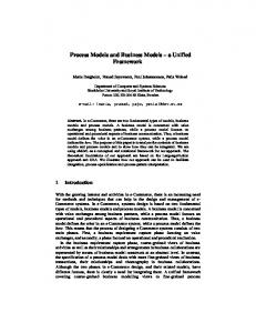
medias and protocols, such as IEEE 802.11b, IEEE 802.3, IEEE 1394, Bluetooth, and RS-232C, and assigns unique address for each object. It also provides message routing so that devices in different kind of network can communicate with each other. The DMS and the IMS use the messaging service to communicate with other devices.
Messaging Service
Network Figure 1. System architecture her wireless portable music player and wireless headphones. John had his high-quality wireless headphones, so he wanted to listen to the music together by connecting his headphones to her music player. All he had to do was push two buttons. First he pushed a button on her music player, and then pushed a button on his headphones. This simple operation established a connection between these two devices, and he was able to enjoy the music. In the above case, we generally need complicated setup operations such as these: First, John tells Mary the name of his headphone. Then she searches for this name on the network member list displayed on her music player. If there are many devices in the network, the member list is so large that this search operation is cumbersome, and sometimes other devices may have the same name. But with the Touch-and-Connect Framework, John can request the connection by simply pushing buttons, instead of performing complicated setup operations.
2.2. System Architecture Figure 1 shows a system architecture overview of the Touch-and-Connect Framework. It consists of four modules in each device: messaging service, device management service (DMS), interface management service (IMS), and connecting interface. Separating these four modules facilitates the reusability of modules and interoperability between various applications. For example, various connecting interfaces with which a user indicates a device are developed with a common IMS (interface management service) module. That not only achieves reusability of the IMS module, but also interoperability between various connecting interfaces (see Section 2.6). Also, the messaging service facilitates message communications between devices. This module is used not only by the protocol of the IMS but also by the application protocols for interaction between DMSs (device management service). Messaging Service: This service wraps various network
Connecting Interface: The connecting interface is the user interface with which a user indicates devices directly. Typically it is two buttons on each devices, as described in Section 2.3. However, other interfaces are also described in Section 2.6. Interface Management Service (IMS): The Interface Management Service (IMS) is the core module in this framework. This service implements the Touch-andConnect protocol described in Section 2.5. The IMS controls the connecting interface and communicates with the IMSs on the other devices. Device Management Service (DMS): The Device Management Service (DMS) is the application layer of this framework. DMS manages device specific functions. Its implementation varies in each kind of device. The only functions that the framework requires for DMS are these: • DMS provides device information. The device information is a data structure that represents the device’s properties. It is described in detail in Section 2.4. • When DMS receives a connection-request event, it executes appropriate action according to the event. Connection-request events are invoked from the IMS when a user requests a connection. Typically, DMS also has the following functions. It is used for managing connections between devices. • DMS has link information, which is the model of connections between devices. This is usually a list of partner device addresses. When the DMS receives a connection-request, this link information is modified. For example, the new partner’s address can be added to the list or removed from it. As it works like a toggle switch, a user can use this framework not only to connect devices, but also to disconnect. • DMS has a server-side feature and/or a client-side feature. – server-side feature: DMS makes the device’s specific functions public to other devices, and an application protocol is defined to control these functions. – client-side feature: DMS controls other devices with the application protocol. The target server devices are determined by the link information.
* light and light is connectable
head phone
display
portable music player
light speaker
P S P S
Then
push plug-button to indicate the source device
video-player push socket-button to indicate the destination device
Figure 2. Two-button interface A
P
S
B
P
S
C
P
S
D
P
S
Push plug-button on A
A
P
S
B
P
S
ENABLE
C
P
S
D
P
S
Push socket-button on B
A
P
S
B
P
S
button state
DISABLE SUCCESS
C
P
S
D
P
S
C
P
S
D
P
S
Several seconds later
A
P
S
B
P
S
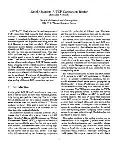
Figure 3. Example sequence of button state Connection-request: If a user requests a connection between two devices with connecting interfaces, a connectionrequest event is transmitted from IMS to DMS in each device. The connection-request consists of the following parameters. (The source device means the first indicated device, and the destination device means the second indicated device.) • Device information of the partner device. (The partner device is the destination device if the local node is the source device, or vice versa.) • Source Flag: local node is the source device or not. This parameter is used when a resulting action is changed with a connecting direction.
2.3. Two-button Interface and Lock Mechanism The two-button interface is one of the connecting interfaces that let a user indicate devices directly. From here on we will use this interface to explain the Touch-and-Connect Framework, because this is the simplest and most typical interface in this framework (other interfaces are treated in Section 2.6.) In this interface, each device has two buttons: a plugbutton (P) and a socket-button (S) as shown in Figure 2. When a user wants to make a connection between device-A (e.g. a portable music player) and device-B (e.g. a headphone), the user first pushes the plug-button on device-A to
music-player
volumecontroller
Figure 4. Connectability-relation example indicate that it is the source device, then the socket-button on device-B to indicate that it is the destination device. This simple sequence of button pushing establishes the connection between the devices. The user can easily relate this operation to inserting a plug into a socket. Now, let’s consider the following operation sequence. (1) user-1 pushes plug-button on device-A (2) user-2 pushes plug-button on device-C (3) user-2 pushes socket-button on device-D (4) user-1 pushes socket-button on device-B In this case, because the system can’t recognize who pushed the button, A – D, and C – B may be connected whereas the users expect to connect A – B, and C – D. In order to exclude these incorrect connections, this method uses the following Lock mechanism that enables the mutual exclusion of users’ operations. Each button can show one of three states: ENABLE, DISABLE, or SUCCESS. A user can push the button only if it is in the ENABLE state, and after pushing the button the user must check that it changes to the SUCCESS state, indicating the success of the operation. By checking for the SUCCESS state, the user can make sure of the success of the operation. During the connecting operation, the plug-button on the other devices shows the DISABLE state (i.e. they are locked) in order to prevent the other users from starting the connecting operations that may result in unwanted connections. The sequence of button states in this case is shown in Figure 3. This method also has manual and automatic cancel function as follows. (1) After the plug-button is pushed, a user can cancel the operation by pushing the same plug-button again. Then the indication of a destination device is canceled, and the buttons return to their initial state. (2) When a user pushes a plug-button and goes away without pushing a socket-button, it is not desirable for the devices to be locked permanently. To avoid this, the operation is automatically canceled after a set delay time. The detailed protocol that accomplishes these functions is described in Section 2.5.
2.4. Device Information Each device has the device information. The device information consists of addrsss, device-type, group-ID, and
bidirectional-link: org.cogma.tnc.display, org.cogma.tnc.video-player bidirectional-link: org.cogma.tnc.speaker, org.cogma.tnc.volume-controller bidirectional-link: org.cogma.tnc.speaker, org.cogma.tnc.music-player bidirectional-link: org.cogma.tnc.speaker, org.cogma.tnc. video-player self-link: org.cogma.tnc.light
※ self-link means the link between the same type Figure 5. Connectability-relation description
extension data. This is used to resolve a relation between devices in IMS, and to select an appropriate action in DMS when a user requests a connection. Device-type and Connectability-relation: The proposed method can be used for various kinds of devices. Each device has a “device-type” that represents the kind of device it is. We consider some simple device-types here, for example, light, video-player, music-player, display, speaker, and volume-controller. The device-type is mainly used so that the DMS can select an appropriate action or application protocol between two indicated devices when a user requests a connection. For example, if a video-player connects to a display, a movie transmission should be done between the devices. And if a video-player connects to a speaker, a voice transmission should be done. We define the connectability-relation that is the relation between devices. The connectability-relation from device-A to device-B means that an appropriate action is defined corresponding to the connecting operation from device-A to device-B. The connectability-relation is used to show connectable devices to a user when the plugbutton is pushed, and to limit the number of locked devices. The connectability-relation between two devices is decided by the device-types of each device, so the connectabilityrelation can be generalized as a relation between devicetypes. Figure 4 shows an example of connectability-relation definition as a directed graph. By using the connectability-relation definition, only the socket-buttons of connectable devices will change to the ENABLE state, and only the minimum number of devices is locked during the connecting operation. If the plug-button of device-A is pushed, the system must lock all the devices connectable to “devices connectable from device-A”. For example, in the definition in Figure 4 , consider the case that a user pushes the plug-button on a volume-controller. Then the socket-buttons of the light and speaker that are connectable from the volume-controller change to the ENABLE state. And the plug-buttons of “video-player, musicplayer, volume-controller, and light” which are connectable to “light or speaker” are locked. So that the system can decide the connectability-relation
between devices, each device has a settings file that describes the connectable relations between device-types. An example of a settings file is shown in Figure 5. This figure shows that the name of a device-type should include the domain name of the organization, like Java package naming, in order to separate name-spaces and avoid name conflicts. Group-ID: Consider the following security and usability problems. • After a user pushes the plug-button, another malicious user may push the socket-button of another device before the first user, creating an unwanted connection. • When many users attempt to connect simultaneously, some users must wait for significant periods for the locked device to be released, and may feel impatient. In this framework, a user can create a private group that devices can join, thus avoiding these problems. Only devices belonging to the same group can be connected to, and be locked. To implement the grouping, each device has a group-ID, and devices that have the same group-ID are considered to belong the same group. By default, a device belongs to “the public group”. If a user wants devices to belong to a specific private group, the user must set up a group-ID for each device. This setup operation should also be simple and intuitive, so we design a special device called group changer. Each group changer has its own setup-ID. If a user requests a connection from a target device to the group changer, the target device’s groupID changes to the group changer’s setup-ID. This means the user can set up the group-ID of the target device without ID input operation. Extension Data: Extension data is information that depends on the device-type. It represents, for example, the object-ID (like a port number in TCP) for each application protocol. It is included in the connection-request parameters and is used by the DMS in order to bring about interactions between devices.
2.5. Touch-and-Connect Protocol The Interface Management Service (IMS) implements the Touch-and-Connect Protocol. This protocol aims to work in ad-hoc networks, which are constructed temporarily on demand. It can work without a server, using broadcast communications instead, and it deals with dynamic node entry and departure. Figure 6 shows a sequence diagram of this protocol. This protocol has some time parameters: request-wait, cancelwait, and success-wait. Their default values are described later. Each device has request-list and lock-list that decide the state of buttons (or other connecting interfaces) and are initially empty.
Lock List
P
A
Source Device (Requester)
A
C
plug-button: DISABLE
Request(A)
Destination Device (Replier)
B
Request(A)
Lock List
A
P
plug-button: DISABLE Request List
Request List
S
A
Plug-button is pushed
socket-button: ENABLE
P Lock List
request-wait
Socket-button is pushed
Reply(B) Cancel(A)
P
Cancel(A)
plug-button: ENABLE Request List
S
Request List
S socket-button: DISABLE
S
Lock List
plug-button: SUCCESS
P plug-button: ENABLE
A
socket-button: ENABLE
Connect to B
Success(A) Connect from A
socket-button: DISABLE
S socket-button: SUCCESS
Figure 6. Protocol sequence Request: When a user pushes the plug-button on a device, the device (requester) broadcasts the Request message. To resolve connectability-relations, this message includes the device information of the requester (except extension data). When a device receives the Request message, and it is from a device that is connectable to the receiver, the message is added to the request-list of the receiver. Lock: When a device receives the Request message, and it is from a device that must lock the receiver, the message is added to the lock-list of the receiver. Reply: When a user pushes the socket-button on a device, the device (replier) sends the Reply message to the requester. The destination requester is the sender of the first element of the request-list. If the lock mechanism works well, the request-list has at most one element. However there are cases in which the request-list has more than two elements, including packet loss and dynamic changes in network topology. If the request-list has more than two elements, it is ambiguous which element the replier replies to, and it may make an incorrect connection. Completion of the Operation: When a requester receives the Reply message, the requester knows that it should connect to this replier. In order to cancel requesting and locking, the requester broadcasts the Cancel message. To signal the success of replying, the requester sends the Success message to the replier. When a device receives the Cancel message, it removes the sender’s element from its request-list and lock-list. Reply and Success messages include the deviceinformation of the sender. When a device receives a Reply or Success message, the connection-request event including that device information are invoked from IMS to DMS in each device.
Manual Cancel: After the plug-button is pushed, a user can manually cancel the operation by pushing the same plug-button again. To accomplish this, when a user pushes the same plug-button again after requesting, the requester broadcasts the Cancel message. Automatic Cancel: If a user pushes the plug-button and goes away without pushing the socket-button, the devices are locked permanently. To deal with this, if the cancel-wait time is exceeded after requesting, the requester broadcasts the Cancel message automatically. Pushing Plug-buttons at the Same Time: When two or more users push the plug-button on devices just at the same time, two requests occur before locking. This is not desirable since having two items on the request-list can cause incorrect connections. To deal with this, devices have a priority order determined by their addresses, and only the request from the highest priority device survives. Accordingly, a requester waits for request-wait period after requesting, then the request becomes valid and the plugbutton becomes SUCCESS state. During this waiting period, if the requester is locked by more prior devices, the requester that has a lower priority broadcasts the Cancel message automatically. The State of Two Buttons: The states of the two buttons on the device are decided by the request-list and the lock-list, except in the case described in the next paragraph. If the lock-list is empty, the plug-button is in the ENABLE state, meaning that the device can begin to request. Otherwise the plug-button is in the DISABLE state, meaning that the device cannot begin to request. If the request-list is empty, the socket-button is in the DISABLE state, meaning that the device cannot reply to any requests. Otherwise the socketbutton is in the ENABLE state, meaning that the device can reply to the request. When a button is in the DISABLE
state, pushing is ignored. To show success in indicating the source device, the plug-button of the requester is placed in the SUCCESS state during the following period: after the request-wait time passes after requesting, and until cancellation of the request (i.e. broadcasting the Cancel message). To show success in indicating the destination device, the socket-button of the replier is placed in the SUCCESS state during the following period: after receiving a Success message, and until the success-wait time passes. Continuously Resend: To deal with dynamic node entries and departures and packet loss, each Request message has a expire time. While the request is valid, the Request message is broadcast repeatedly at message-repeating-interval. Cancel messages are also broadcast several times. In order to reduce network traffic, as the total number of valid requests increases, the message-repeating-interval increases automatically.
deal with the case in which user-A and user-B begin connecting operations almost simultaneously. First, user-A pushes a button in the SOURCE-ENABLE state. Immediately after that, user-B accidentally pushes a button in the DESTINATION-ENABLE state because the button was just in the SOURCE-ENABLE state. This can produce an unwanted connection. Compared with the two-button interface, the one-button interface has the advantage that it can be implemented with lower parts’ cost and smaller size. However, this has the disadvantage that it may cause incorrect connections, because some users may not be able to recognize that a button state was changed in the change-mode-wait period.
3. Implementation We implement a prototype system of this framework to work in the following environment.
Default Values of the Time Parameters: The followings are default values of the time parameters: request-wait = 3000 ms, cancel-wait = 30000 ms, success-wait = 2000 ms.
Programming and runtime environment: Personal Java 1.1.3, and intent 1.2 (high-performance java runtime environment for embedded systems)
2.6. Other Connecting Interfaces
Network environment: IPv4 (IEEE802.11b)
The most typical connecting interface in the Touch-andConnect Framework is two buttons on each device, as described in Section 2.3. However, other interfaces are also available, including one-button interface, and laser pointer interface. We show only the one-button interface here, because of a page limit. The Touch-and-Connect Framework has interoperability between connecting interfaces so that a user can use two different interfaces to indicate two devices, because these interfaces use the same Touch-and-Connect protocol in Section 2.5. For example, first, a user uses the two-button interface to indicate a source device, then the user can use the one-button interface to indicate a destination device. One-button Interface: This interface is only one button on each device. In order to represent the state of the conventional two buttons with only one button, the button has the five states in Table 1. Firstly, in order to indicate the source device, a user pushes the button only while it is in the SOURCE-ENABLE state, and checks that it changes to the SOURCE-SUCCESS state. Then in order to indicate the destination device, the user pushes the button in the DESTINATION-ENABLE state, and checks that it changes to the DESTINATION-SUCCESS state. Table 1 shows the basic behavior rules of the one-button interface. However, in the third rule, the button is in the DISABLE state during the following period: after a device becomes able to reply, until the change-mode-wait time (1000 ms by default) passes. Then the button changes to the DESTINATIONENABLE state as per the rules in the Table. This is to
over
wireless
Ethernet
Host computer: LAMB-EM-01 (small Linux PC for embedded systems, 486SX 66MHz CPU, 16Mbytes RAM), and ordinary Windows notebook PC We have currently implemented a two-button interface and a one-button interface in connecting interfaces. The state of a button is represented by the color of the button. In the two-button interface, black (no color) means the DISABLE state, green means the ENABLE state, and red means the SUCCESS state. In the one-button interface, green means SOURCE, red means DESTINATION, plain lighting means ENABLE, and blinking means SUCCESS. For example, plain lighting of green means the SOURCE-ENABLE state, and blinking red means the DESTINATION-SUCCESS state.
3.1. Applications We have created some software emulator devices and real hardware devices, for example, a volume-controller, light, desk-fan, relay-switch, and group changer. These devices have two-button or one-button interfaces such as Figure 7. (Some two-button interfaces on hardware devices in the figure are still an old one/two-button version instead of the plug/socket-button version.) The volume-controller has up and down buttons to control other devices. By connecting the volume-controller to the target device (light, desk-fan, or relay-switch), a user can control the brightness of the light, wind velocity of the desk-fan, and ON/OFF of the relay-switch. By connecting
Table 1. Behavior rules of the one-button interface (the higher rule has higher priority) Condition
Button State (and its meaning)
successful request (during my request is
SOURCE-SUCCESS (success at indicating
valid)
the source device)
successful reply (during a few seconds after
DESTINATION-SUCCESS (success at indi-
receiving the Success message) can reply (request-list isn’t empty)
cating the destination device)
DESTINATION-ENABLE (ready to indicate the destination device) DISABLE (cannot push) SOURCE-ENABLE (ready to indicate the source device)
locked (lock-list isn’t empty) default (otherwise)
Volume controller
Desk fan
Light
Behavior when button is pushed cancel
reply
request
Relay switch
Connecting interface
Light (software emulator) Volume controller (software emulator)
Visualization of connections
Group changer (software emulator)
Volume controller (one button interface)
Figure 7. Implemented devices two of these target devices, a change of the volume-value (for example, brightness of light) can be linked between these two devices. That is, when the volume-value of one increases, the volume-value of the other also increases. And a user can easily set up the group-ID by connecting any devices to the group changers. Controlling these devices demonstrates the usefulness of this framework. We have also implemented some extensions in the DMS, which accomplishes the visualization of connections. The visualization software in Figure 7 represents the devices in the network and the connections between them.
4. Evaluation The connecting management framework should have the usability and deal with the environment that there are many devices in the network and many users use them. We have evaluated these properties of the proposed method by the following experiments.
4.1. Experiment 1 We have evaluated usability of the proposed method by measuring operation time and subjective evaluation by a questionnaire. Subjects were six computer science university students. We compared the following three interfaces, which were a conventional name selection interface and two connecting interfaces of the Touch-and-Connect framework. Figure 8 shows a experiment system. Name selection interface: This is a conventional interface to request a connection. When a user wants to connect devices, operates as follow. First the user pushes a search button in the source device, then all device names are listed in a member list box. Then the user selects the destination device name on the member list, and pushes a connect button. We assumed that the member list box could show four members at once, and there were 24 members in the
Name
5
Member list box
4.5
One-button interface
Two-button interface
Search button
Name selection interface
4
Connect button
3.5 score
Experiment System
Simplicity Understandability Comfort
3 2.5
Task indication icon
2 1.5 1
Figure 8. Experiment system
Name selection
Two-button
One-button
Figure 10. Subjective evaluation of usability
6000 5000
ms
4000 3000 2000 1000 0 Name selection
Two-button
One-button
Figure 9. Average operation time network. The list box has a scroll bar, and its members are sorted by dictionary order. Two-button interface: This is the most typical connecting interface in the Touch-and-Connect framework, mentioned in Section 2.3. One-button interface: This is another connecting interface in the Touch-and-Connect framework, mentioned in Section 2.6. First, we measured the operation time of each interface. The experiment system in Figure 8 works on a notebook PC with a touch-panel display, and there are 12 softwareemulator devices in the display. The system randomly indicates two of these devices as a task by task indication icons. A user connects these two devices by touching the display with a pen. The connection direction (which is the source device) is not cared. We assigned 30 tasks continuously and measure the each operation time, which is from the indication of the task to the completion of the operation. Figure 9 shows the average operation time for each interface. This implies operation simplicity of the proposed method. The two interfaces of Touch-and-Connect framework only need a half of a operation time for the conventional name selection interface. It seems that because of change-mode-wait period (see Section 2.6), the one-button
interface needs about 0.8 second longer than the two-button interface. Then, we required subjects to use this system with another subject simultaneously. Finally, we take subjective evaluation of each subject by a questionnaire. Contents of the questionnaire are score (1–5) of simplicity, understandability, and comfort. The simplicity means the operation is less cumbersome. The understandability means it is easy to learn the interface. And the comfort means a user doesn’t feel impatient while using the interface. Figure 10 shows the average score of all subjects for each interface. This implies that the proposed method has higher simplicity and comfort as compared with the conventional name selection interface. The result of the evaluation exemplified the usability of the proposed method.
4.2. Experiment 2 We have evaluated that the lock mechanism of the proposed method prevents the incorrect connections caused by the independent operations of users. Subjects were eight computer science university students, which fell into two groups. Accordingly, each group had four subjects. Experiment system was the same as the experiment 1, except that a task indicating interval (after that a subject completes a task, until the system indicates a next task to the subject) is random under exponent distribution with mean 10000 ms. There were four network connected notebook PC terminals, and each subject used each terminal. We required the four subjects to use this experiment system simultaneously. A subject was apart from other subjects and couldn’t see other subjects’ operations. We counted incorrect connections during ten minutes. We compared two interfaces, which were the two-button interface of the Touch-and-Connect framework (same as experiment 1) and the following no-lock interface.
Table 2. The count of incorrect connections and failure tasks during 10 minutes. Interface Group Count of Incorrect Connections Count of Failure Tasks Count of Total Tasks Failure Task Ratio
Two-button
No-lock
group1
group2
group1
group2
2
3
244
295
2
4
70
65
163
168
123
142
1.2%
2.4%
56.9%
45.8%
No-lock interface: This is the most trivial interface for requesting connections by buttons. Each device has one button without any status indicators. The first pushing means the source device, the second pushing means the destination device, and the connection between these two devices is initiated. Then the system returns to initial state, so the third pushing means the source device again. The implementation of the no-lock interface is based on the one-button interface of the Touchand-Connect framework, however no lock mechanism (namely the lock-list is always empty), no button state, no manual cancel operation, and no change-mode-wait period (see 2.6). Table 2 shows the count of incorrect connections and failure tasks for each interface and each group. A task fails if at least one incorrect connection occurs during the task — after the task is indicated, until a next task is indicated. If an incorrect connection between two subjects occurs, the both tasks fails. The failure task ratio equals the count of failure tasks divided by the count of total tasks. The result implies that incorrect connections frequently occur without the lock mechanism, and the lock mechanism of the proposed method almost prevents these incorrect connections.
5. Related Work The following works are related to this research. Universal Plug and Play[2], Jini[3], HAVi[4], and ECHONET[5] are technical specifications to connect networked appliances. With these specifications, a device opens its specific functions to the network, and interacts with other devices. But user interfaces for managing connections are not seriously considered. When users want to connect the devices, typically they are required to perform setup operations such as setting addresses or names. In STONE[6] or AMIDEN[7] architecture, when a user wants to integrate devices, he inputs a service type. Then
the system searches for appropriate devices automatically, using device-types required by the service type. In the Follow-me application[8], the system determines the locations of users with supersonic sensors, and the display which is the closest to the user is selected automatically as a workspace. However, in an environment where there are numerous devices, automatic device selection is sometimes inflexible. Accordingly, users will want direct device indication methods like Touch-and-Connect. Pick-and-Drop[9] is a direct manipulation technique for multi-computer environments. In Pick-and-Drop, users can request data translations over the computers directly by pointing at two GUI objects on different computers with a pen. Touch-and-Connect can be used for the same purpose as Pick-and-Drop with context-menus including GUI connecting interface. Pick-and-Drop requires a central management server, and users have to carry a special device with a unique ID such as a pen. Not so with Touch-and-Connect. In FUI (Fingerprint User Interface)[10], a user can use his finger to input data for storage (called finger-memo). A user can request data translations over computers, as with Pick-and-Drop, where a user uses his finger instead of a pen. FUI can also be used for requesting a connection between devices as with Touch-and-Connect. FUI uses fingerprints as a unique user ID so that many users can use the system simultaneously. The Touch-and-Connect Framework uses a lock mechanism instead of unique user ID. It involves waiting time due to locks, and has some security problems, but it can be implemented at lower cost than fingerprint recognition. The Touch-and-Connect Framework doesn’t require a central management server whereas FUI requires a management server in the network. Resurrecting Duckling[11][12] is a security model for information appliances in ad-hoc wireless networks. When a user purchases a device, he teaches the device that he is its owner. By this means the device is prevented from communicating with other users’ devices. This operation is called imprinting. The group-ID setup operation with a group changer (see Section 2.4) can be regarded as an imprinting operation. Like Resurrecting Duckling, the group changer can be extended to have secret information such as an encryption key. This secret information is safely sent to a device using public-key encryption when the device joins to the group.
6. Future Tasks The following are unsolved problems and tasks for the future. Extendability and Flexibility: Idealy a connecting management framework should be extendable. Currently, the connectability-relation and an application protocol between two device-types is defined beforehand. It is desirable that
two devices that don’t know each other beforehand can interact and cooperate. The mobile code approach is suitable for designing such an extendable framework [13][14]. We have already developed a mobile agent system for ad-hoc network environments [15], so we will design a more flexible connecting management framework employing this system. Hidden Terminal Problem: Currently we assume a closed network in which each node can communicate with all other nodes. But in wide-area wireless ad-hoc networks we should consider the hidden terminal problem. Near the edge of the coverage area, the request-list may have more than two elements, causing an incorrect connection. To solve this problem, the locked area should be twice the size of the requested area. However, this is difficult to achieve unless the wireless communication module can measure the distance to the source node. If the requester locks all the devices within two-hops, it may cause a broadcast storm by message routing, and the locked range may be too wide. Currently we have no reasonable solutions.
7. Conclusion In this paper, we have proposed a user-friendly connecting management framework called the “Touch-and-Connect Framework”. With this framework, a user can request a connection between any devices by directly touching these two devices without any complicated setup operations. It uses a lock mechanism for smooth functionality in the pervasive computing environment where there are many devices and many users. Its protocol doesn’t assume any central management servers, so it works even in an ad-hoc network environment. We have also demonstrated the feasibility of this framework with the implementation of a prototype system and some applications, and have exemplified the usefulness with subject experiments.
References [1] Mark Weiser, “The computer for the 21st Century,” Scientific American, Vol.265, No.3, pp.94–104, 1999. [2] Microsoft Corporation, “Understanding Universal Plug and Play : A White paper,” http://www.upnp.org/resources/ [3] Jim Waldo, “The Jini architecture for network-centric computing,” Communications of the ACM, Vol.42, No.7, pp. 76–82, 1999. [4] HAVi - Home Audio / Video Interoperability, http://www.havi.org/
[5] ECHONET (Energy Conservation and Homecare Network) Consortium, http://www.echonet.gr.jp/english/index.htm [6] Y.Sawahata, K.Sugita, M. Minami, H. Morikawa, and T. Aoyama, “A Design and Evaluation of Connection Setup and Management Mechanism for Network Service Synthesizer,” Multimedia, Distributed, Cooperative and Mobile Symposium (DICOMO 2001), pp.103-108, 2001. (Japanese) [7] M.Minoh and T.Kamae, “Networked Appliances and Their Peer to Peer Architecture AMIDEN,” IEEE Communications Magazine, Vol.39, No.10, pp. 80–84, 2001. [8] Andy Harter, Andy Hopper, Pete Steggles, Andy Ward and Paul Webster, “The Anatomy of Context-Aware Application,” Proceedings of the fifth annual ACM/IEEE international conference on Mobile computing and networking (MOBICOM’99), pp. 59–68, 1999. [9] Jun Rekimoto, “Pick-and-Drop: A Direct Manipulation Technique for Multiple Computer Environments,” Proceedings of the 10th annual ACM symposium on User interface software and technology (UIST’97), pp. 31–39, 1997. [10] Atsushi Sugiura and Yoshiyuki Koseki, “A User Interface Using Fingerprint Recognition: Holding Commands and Data Objects on Fingers,” Proceedings of the 11th annual ACM symposium on User interface software and technology (UIST’98), pp.71–79, 1998. [11] Frank Stajano and Ross Anderson, “The Resurrecting Duckling: Security Issues for Ad-hoc Wireless Networks,” Proceedings of 3rd AT&T Software Symposium, 1999. [12] Frank Stajano, “The Resurrecting Duckling - what next?,” Proceedings of the 8 th International Workshop on Security Protocols, 2000. [13] Kari Kangas and Juha Roning, “Using code mobility to create ubiquitous and active augmented reality in mobile computing,” Proceedings of the fifth annual ACM/IEEE international conference on Mobile computing and networking (MOBICOM’99), pp.48–58, 1999. [14] W. Keith Edwards, Mark W. Newman, Jana Sedivy, and Shahram Izadi, “Challenge: recombinant computing and the speakeasy approach,” Proceedings of the eighth annual international conference on Mobile computing and networking (MOBICOM 2002), pp.279–286, 2002. [15] cogma (COoporative Gadgets for Mobile Appliances), http://www.cogma.org/ (Japanese)