Abstract. Hexagonal structure is different from the traditional square struc- ture for image representation. The geometrical arrangement of pixels on hexag-.
c 2007 Institute for Scientific ° Computing and Information
INTERNATIONAL JOURNAL OF INFORMATION AND SYSTEMS SCIENCES Volume 3, Number 3, Pages 492–509
UNIFORM IMAGE PARTITIONING FOR FRACTAL COMPRESSION ON VIRTUAL HEXAGONAL STRUCTURE XIANGJIAN HE, HUAQING WANG, WENJING JIA, QIANG WU, NAMHO HUR, JINWOONG KIM, AND TOM HINTZ Abstract. Hexagonal structure is different from the traditional square structure for image representation. The geometrical arrangement of pixels on hexagonal structure can be described in terms of a hexagonal grid. Uniformly separating image into seven similar copies with a smaller scale has commonly been used for parallel and accurate image processing including image compression on hexagonal structure. However, all the existing hardware for capturing image and for displaying image are produced based on square architecture. It has become a serious problem affecting the advanced research based on hexagonal structure. Furthermore, the current techniques used for uniform separation of images on hexagonal structure do not coincide with the rectangular shape of images. This has been an obstacle in the use of hexagonal structure for image processing. In this paper, we briefly review a newly developed virtual hexagonal structure that is scalable. Based on this virtual structure, algorithms for uniform image separation are presented. The virtual hexagonal structure retains image resolution during the process of image separation, and does not introduce distortion. Furthermore, images can be smoothly and easily transferred between the traditional square structure and the hexagonal structure while the image shape is kept in rectangle. As an application of image partitioning, we present a Fractal Image Compression (FIC) method on the virtual image structure by adopting Fisher’s basic FIC method on the traditional square image structure. The modification on the definition of range block and domain block is implemented in order to utilize the enhanced image structure. The results of the FIC approach applied to testing images are analyzed and show higher fidelity. Key Words. Hexagonal structure, image scaling, Spiral Architecture, fractal image compression, image partitioning.
1. Introduction Computer Vision and Image Processing is a computationally expensive field in which many operations require massive computations, especially when large data sets are involved such as those for stereo image matching and feature extraction. Parallel processing using a cluster consisting of multiple computers is a straightforward method to speed up image processing. Cluster-based parallel computing has the advantages of low cost and high utility. On the other hand, it has the disadvantages of high communication latency and irregular load patterns on the computing nodes [1]. Its performance mainly depends on the amount of and the structure for communications between processing nodes. Therefore, as an application for parallel Received by the editors October 1, 2006 and, in revised form, November 28, 2006. 492
FRACTAL COMPRESSION ON VIRTUAL HEXAGONAL STRUCTURE
493
image processing, image separation or partitioning for task dividing is critical in a parallel algorithm for image processing. Many types of image partitioning have been proposed [2] on traditional square image structure such as Row Partition, Column Partition and Block Partition. All of these partition methods do not intend to separate an image into similar copies (or sub-images). Hence, when the sub-images are assigned to various computer nodes for parallel processing, the load-balancing is not guaranteed. The method for image partitioning presented in [3] is based on a hexagonal image structure, called Spiral Architecture (SA) [4], which is inspired from anatomical considerations of the primate’s vision. It partitions the input image uniformly into a number of sub-images. Each sub-image is a near (or similar) copy of the input image with a smaller scale, while all of the sub-images are mutually exclusive and the original image information is all kept in the sub-images. Every sub-image can be processed independently and in parallel by an individual node without data exchange between the nodes. Furthermore, the workload on every node is almost the same as that on any other node because of the uniform partition. Consequently, the computational complexity is greatly reduced and the processing time is significantly shortened. The work shown in [3] has the following shortcomings. First of all, the shape of input images is hexagon-like and does not coincide with rectangular shape of traditional images. Secondly, the image partition method is computationally expensive. Thirdly, images are represented on a mimic Spiral Architecture that introduces a loss on image resolution and creates image distortion when the subimages have a rotated angle from the original image. In order to take the advantages and suppress the disadvantages of SA, in this paper, we present a novel method for uniformly separating image into four similar sub-images based on a newly defined virtual hexagonal image structure [5]. The hexagonal structure can be smoothly converted from the square structure without changing the image shape. In this virtual structure, hexagonal pixels can be easily located through simple computations. It avoids the necessity of using a computation expensive method to compute pixel locations and hence avoids the need to build a large table to record the location information. This virtual structure hardly changes the image resolution and almost does not introduce image distortion. As another application of uniform image partitioning, a Fractal Image Compression (FIC) method is presented in this paper. FIC is an area of intensive research in the previous decades [6][7]. During more than two decades of the development in FIC, a lot of researches have been done to improve the performance. The existent enhanced approaches can be classified into the following categories [8]: • • • • •
Partition methods imposed on the image to obtain range blocks; Methods for selection of the pool of domain blocks; Selection of transforms on the domain blocks; Searching methods for locating suitable domain blocks; Representation and quantization of the transform parameters.
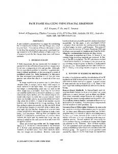
The research work on FIC to be presented in this paper, however, is based on a different image structure, namely hexagonal structure. A hexagonal structure called the Spiral Architecture (SA) [4] was proposed by Sheridan in 1996, on which each hexagonal pixel is identified by a designated positive seven-based integer. These numbered hexagons tile the plane in a recursive modular manner along the spiral direction (see Figure 1). Based on the spiral addressing system, there are two operations defined on SA, i.e. spiral addition and spiral multiplication. These two
494
X. HE, H. WANG, W. JIA, Q. WU, N. HUR, J. KIM, AND T. HINTZ
operations were used in our previous work [9] for the definition of range blocks and domain blocks when adopting FIC on SA.
34 33
35 30 36
32 24 23
31 25
20
42
3
21 14
55 50
6 52
63
65 60
62
66 61
56 51
64
16 11
53
1
10
54
5
15
126
46 41
0 2
13
45 40
4
26
22
44 43
Main rotating direction Secondary rotating direction
Figure 1. Spiral Architecture with spiral addressing. The FIC method based on a hexagonal structure in this paper inherits the FIC methods on square image structure introduced by Fisher [6] and also inherits the ideas proposed on SA for uniform image separation. All range blocks have the same size. Although the performance of this algorithm in terms of compression ratio and fidelity can be further improved, the performance analysis well evaluates the capabilities of the proposed FIC on hexagonal structure in comparison to FIC on square image structure. For a better comparison, the proposed method follows the same contractive transformation applied to domain blocks and nearest neighbor search used in locating suitable domain blocks on square structure. The definition of range block and domain block, however, is slightly adjusted to take the geometrical advantages of hexagonal structure. It can be easily found as shown in the experimental results that this FIC on hexagonal structure offers better fidelity with different compression ratios for all test images. The rest of this paper is organized as follows. In Section 2, we briefly review the Spiral Architecture. In Section 3, we introduce the construction of a new virtual hexagonal structure. A new technique for uniform image partition is presented in Section 4. Experimental results for uniform image partitioning are demonstrated in Section 5. The approach for FIC on the virtual structure following a uniform partitioning algorithm is presented in Section 6. Section 7 demonstrates the experimental results using the FIC method. We conclude in Section 8. 2. Spiral Architecture On Spiral Architecture, an image is represented as a collection of hexagonal pixels. Each pixel has only six neighbouring pixels with the same distance to it. Each pixel is identified by a number of base 7 called a spiral address. The numbered (or addressed) hexagons form the cluster of size 7n , where n is a positive integer. These hexagons starting from address 0 towards address 7n tile the plane in a
FRACTAL COMPRESSION ON VIRTUAL HEXAGONAL STRUCTURE
495
recursive modular manner along a spiral-like curve. As an example, a cluster with size of 72 and the corresponding spiral addresses are shown in Figure 1. The image space formed on the Spiral Architecture always has a hexagon-like shape. This shortcoming restricts the applications of image processing on hexagonal structures. Our approach in this paper will overcome this disadvantage. Two algebraic, useful and important operations have been defined on Spiral Architecture based on spiral addresses. They are Spiral Addition and Spiral Multiplication. These two operations correspond to two transformations on Spiral Architecture, which are translation and rotation with a scaling. Spiral Multiplication is also often applied to uniformly separate images on Spiral Architecture for parallel processing. In this paper, we perform an algorithm for image partition on a hexagonal structure without using computationally expensive Spiral Multiplication. Our algorithm will maintain the important property that none of image (intensity) information is lost during the separation process. 3. Virtual Hexagonal Structure (VHS) In this section, we review the construction of a new virtual hexagonal structure [5]. To construct hexagonal pixels, each square pixel is first separated into 7 × 7 smaller pixels, called sub-pixels. To be simple, the light intensity for each of these sub-pixels is set to be the same as that of the pixel from which the sub-pixels are separated. Each virtual hexagonal pixel is formed by 56 sub-pixels arranged as shown in Figure 2. To be simple, the light intensity of each constructed hexagonal pixel is computed as the average of the intensities of the 56 sub-pixels forming the hexagonal pixel when necessary.
Figure 2. The structure of a single hexagonal pixel in the virtual hexagonal structure. Figure 3 shows a collection of seven hexagonal pixels constructed with spiral addresses from 0 to 6. From Figure 3, it is easy to see that the hexagonal pixels constructed in this way tile the whole plane without and spaces and overlaps. From Figure 3, it can be easily computed that the distance from pixel 0 to pixel 1 or pixel 4 is 8. The distance from pixel 0 to pixel 2, pixel 3, pixel 5 or pixel 6 is p 72 + 42 = 8.06 which is close to 8. Hence, the feature of equal distance is almost retained and hence this construction hardly introduces image distortion.
496
X. HE, H. WANG, W. JIA, Q. WU, N. HUR, J. KIM, AND T. HINTZ
4 5
3
j 0 6
2 1 k
Figure 3. A cluster of seven constructed virtual hexagonal pixels. Through this paper, we assume that original images are represented on a square structure arranged as 16M rows and 16N columns, where M and N are two positive integers. This assumption guarantees that sub-images to be obtained in this paper has exactly the same size and are of a complete rectangle shape. Let the centre of the virtual hexagonal structure be located at the middle of 8M -th row and (8M +1)th row, and at 8N -th column. Let us denote the light intensity of the square pixel at row m and column n by Q(m, n), where 0 ≤ m ≤ 16M and 0 ≤ n ≤ 16N . Here, we use row 0 to represent the first row (i.e., top row) and column 0 to represent the first column (i.e., left column) and so forth. Note that there are (7×16M =) 112M rows and (7×16N =) 112N columns in the virtual square structure consisting of virtual sub-pixels obtained from the original square pixels. Let us denote the light intensity of the square sub-pixel at row m and column n by P (m, n), where 0 ≤ m ≤ 112M and 0 ≤ n ≤ 112N . Let us construct the first hexagonal pixel using the 56 sub-pixels with centre located in the middle of rows 56M − 1 and 56M and at column 56N − 1 of the virtual square structure. This first pixel is called the central hexagonal pixel in the hexagonal structure. It is corresponding to the pixel with spiral address 0 in the Spiral Architecture. After the 56 sub-pixels for the first hexagonal pixel are allocated, all sub-pixels for all hexagonal pixels can be assigned. For our uniform partition algorithms, the assignment of sub-pixels to corresponding hexagonal pixels is not explicitly required. We do not need to compute the intensities for the virtual hexagonal pixels. After image processing for uniform partition, the intensity of each square pixel can be computed as the average of the light intensities of the 7 × 7 sub-pixels separated from this square pixel. 4. Uniform Image Partition In this section, we will perform algorithms for separating image represented on the virtual hexagonal structure into four sub-images that look similar and have exact the same image size. The idea is to define rows and columns as images represented on the square structure. Then, each sub-image is a collection of hexagonal pixels from every second row and column. It is not as obvious as in the square structure to find the column and the row of each hexagonal pixel. It is not obvious
FRACTAL COMPRESSION ON VIRTUAL HEXAGONAL STRUCTURE
C=-4
C=-3
C=-2
C=-1
C=0
C=1
C=2
C=3
497
C=4
34
25 20
14 15
12
56
52 51
64 65
63 60
16 11
50
6 1
10
55
53
0 2
13
54
5
3
21
46 41
4
26
22
42
31
24
40
36
32
45
43
30
23
44
35
33
66
62 61
Figure 4. Columns on a hexagonal structure. either to know which pixels form the first row or the first column of a sub-image. We follow the following three steps for the uniform image separation. We first define the rows and columns on the virtual hexagonal structure, and propose an algorithm for computing the row and column of the hexagonal pixel that a given sub-pixel belongs to. Then we present an algorithm for the extraction of the first sub-image. In the third step, algorithms for construction of the second, the third and the fourth sub-images are proposed. 4.1. Pixel Row and Column. Assume a given sub-pixel is at row p and column q. Let R and C represent the number of rows and number of columns needed to move from the central hexagonal pixel to the hexagonal pixel containing the given sub-pixel taking into account the moving direction corresponding to the signs of R and C. Here, pixels on the same column are on the same vertical line. For example, as shown in Figure 4, pixels with addresses 43, 42, 5, 6, 64, 60 and 61 are on the same column with C = 1. The row with R = 0 consists of the pixels on the horizontal line passing the central pixel and on the columns with even C values, and the pixels on the horizontal line passing the pixel with address 3 and on the columns with odd C values. Other rows are formed in the same way. For example, pixels with addresses 21, 14, 2, 1, 6, 52, 50 and 56 are on the same row with R = 1. Figure 5 shows rows in a hexagonal structure consisting of 49 hexagons. Following the algorithm proposed in [10], the C and R corresponding to the given sub-pixel can be computed from P 1, P 2, Q1 and Q2 defined below. ¾ ½ |q − 56N + 1| , Q1 = sgn{q − 56N + 1} max int c|c ≤ 7 Q2 = (q − 56N + 1) mod 7, ¾ ½ |p − 56M + 1| , P1 = sgn{p − 56M + 1} max int c|c ≤ 8 P2 = (p − 56M + 1) mod 8.
498
X. HE, H. WANG, W. JIA, Q. WU, N. HUR, J. KIM, AND T. HINTZ
34
23
R=0
22
42
31
24 R= -1
25 20
46 41
4
54
5
3 26
55
53
0 2
21
40
36
32
45
43
30 R= -2
44
35
33
50
6
R=1 14 13
1 15
R=2
63
10 12 R=3
51 65
60
16 11
56
52 64
62
66 61
Figure 5. Rows on a hexagonal structure. 4.2. Construct the First Sub-image. Let h be an arbitrary given hexagonal pixel on a hexagonal structure. Let us denote the values of C and R corresponding to h by Ch and Rh respectively. Then the first sub-image S1 is formed by the hexagonal pixels that satisfy the following conditions: Ch mod 2) − (Rh mod 2) = 0}. 2 From the above representation, we can see that any hexagonal pixel must be on the column with even C value; and if the pixel falls onto column with even C/2 value then R value for the pixel must be even as well, otherwise R must be odd. The arrangement of the hexagonal pixels in S1 is made as follows. We keep the location of the central pixel (with C = 0 and R = 0) unchanged, and move any other hexagonal pixel towards the central pixel by its half distance from it. Note that the distance between two adjacent columns is 7 sub-pixels long, and the distance between two adjacent rows is 8 sub-pixels long. Hence, any pixel belonging to S1 except the central pixel will move by |Ch |/2 × 7 sub-pixels leftwards (or rightwards when Ch is negative) then by |Rh |/2 × 8 upwards (or downwards when Rh is negative). After the above-mentioned procedure, the first sub-image is formed and it is sitting in the middle of the original image area. In order to fit all four sub-images onto the same image area after the four sub-images are formed, in the next step, we move S1 to the top left corner of the original image area such that S1 will exactly occupy the top 8M rows and left 8N columns of the original rectangular image area. Note that the new centre of S1 will be located in the middle of rows 28M − 1 and 28M and at column 28N − 1 of the virtual square structure. Hence, to move the S1 to the top left corner, we need only move all sub-pixels in S1 upwards by 28M sub-pixels and leftwards by 28N sub-pixels. S1 = {h|Ch mod 2 = 0, (
4.3. Construct Other Sub-images. The second sub-image S2 consists of all hexagonal pixels that are one hexagonal above or below the pixels in S1 . The third sub-image S3 consists of all hexagonal pixels that are next to the pixels in S1 but sitting at the left-bottom side. Similarly, the fourth sub-image S4 consists of all
FRACTAL COMPRESSION ON VIRTUAL HEXAGONAL STRUCTURE
499
hexagonal pixels that are next to the pixels in S1 but sitting at the right-bottom side. Let us now construct sub-images 2 trough 4 one after another in the following. 4.3.1. Construction of S2 . To construct S2 , we first translate all sub-pixels downwards by 8 sub-pixels. By doing so, the first hexagonal pixel (with spiral address 4 as shown in Figure 1) of S2 that is the one right above the central pixel with spiral address 0 is moved to the central position with C and R both equal to 0. After the translation, the bottom eight rows in the virtual square structure will be moved out from the original image area. In order not to lose any image information after the translation, we fill the top eight rows of the virtual square structure by those sub-pixels at the bottom eight rows while performing the translation. If we use M 1 to denote 112 × M , N 1 to denote 112 × N , and P [i][j] to denote the value at the sub-pixel (i, j), the pseudo code for this movement is shown as follows. for ( i = 0 ; i < M1 ; i ++ ){ for ( j = 0 ; j < N1 ; j ++ ){ if ( 0