USING THE COMSOL IN MODELING OF SOFT TISSUES P. Nardinocchi1 , T. Svatoˇ n2 , L. Teresi3 1: Universit` a degli Studi di Roma La Sapienza, Facolt`a di Ingegneria, Dipartimento di Ingegneria Strutturale e Geotecnica (supervisor) 2: University of West Bohemia, Faculty of Applied Sciences, Department of Mathematics 3: Universit` a degli Studi Roma Tre, Facolt`a di Ingegneria, Dipartimento di Strutture (supervisor) Abstract Modeling of soft tissues is a modern trend of investigation in the field of biomechanics. This contribution involves demonstration of implemented non-linear elastic steady problem with some special results of numerical experiments. We will focus on hyperelastic nearly incompressible transversaly isotropic materials where the homogenous matrix will be reinforced with continously distributed fibres. Particulary there will be performed inflation tests.
1
Problem Formulation
We use the incompressible transversely isotropic material see [4]. For the tube matrix we will use the neo-Hookean material see [1] and the fiber reinforcing will be in the circumferential sense. The balance principle of the virtual power on the actual configuration is Z
P (w) =
(−T · ∇w + f · w) dv +
Bt
Z
t · w da = 0,
for all w test ,
(1)
∂Bt
where T is the stress tensor, f bulk load and t boundary load see [3] for further details. The stress T depends on the displacement u through a constitutive equation. So dealing with nonlinear elasticity we look for the reference stress T and the displacement field u, thus we look for the actual configuration, knowing boundary and bulk loads on this configuration, kinematics boundary conditions and constitutive prescriptions. Initially we do not know how the actual configuration looks like and it is convenient to establish the balance principle in terms of the reference quantities on the reference configuration and we have Z
P (wm ) =
(−S · ∇wm + ˆf · wm ) dv +
B
Z
ˆt · wm da = 0,
for all wm test
(2)
∂B
with S the reference stress which in general depends on the displacement gradient ∇u through a constitutive equation. Let us note that the quantity wm denotes the material velocity and ˆf and ˆt are the reference bulk load and boundary load respectively. Our problem formulation is that we look for a displacement field u such that is satisfied the equation (2) and the apropriate kinematics boundary conditions on part of ∂B.
2
Implementation
We need to implement the balance equation and constitutive legacies so we use apropriate predefined data structures, but as first we must define the geometry and physics and for numerical
analysis we must define apropriate mesh. Let us note that there are two different modes how to use COMSOL Multiphysics. Implement all throught the COMSOL program or create the MATLAB script. The second one seems more adaptable for geometry and material property changes. So it will be briefly described how to generate this MATLAB script and modify them. For every different model we can use its own geometry and after we can switch among the predefined models for which the analysis we would like to do. We can also perform numerical experiments for all predefined models at the same time. Because a computation in three dimensions is very time consuming end memory expensive it will be sufficient to use one geometry. Hence we will use only one model in three dimensional space. After we load Model Navigator we set the ambient space to three dimensions and choose Weak Form, Subdomain from offered PDE Modes in COMSOL Multiphysics. We need to solve a steady analysis problem now but for future use we can choose Time-dependent analysis task. Finaly we can define Dependent variables u v w as displacements according to coordinate system axes. Because of usage of displacement gradient we choose finite elements almost of the second order. For our analysis the second order Lagrange element (see [2]) yields very good results.
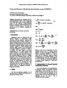
Geometry Preparing geometry we set the shape of our object. It will be a tube with inner radius, outer radius and height as Ri , Re and H respectively. Let us note that it will be smart for often geometry changes to set these values as parameters. The central point of the lower base coincides with the origin of the cartesian coordinate system.
Figure 1: Basic geometry settings
Balance Equation Implementation For the balance equation implementation we must substitute our unknowns into the predefined weak-form diffusion equation with the unit bulk source fu = (1, 1, 1)T . Z
u˙ · wm dV =
B
Z
(−∇u · ∇wm + fu · wm ) dV
for all wm test .
(3)
B
So for the stationary problem we pose the timederivative of the displacement u˙ equal to zero and follow the principle idea that dweak=weak corresponds to the equation (3). The all other kinematics (Dirichlet) and Neumann initial and boundary conditions on ∂B × T0 and ∂B × T are set to zero implicitly, here T denotes the timeline.
Boundary Conditions For our inflation tests the upper and lower base is movement free in a radial direction but both of the basis are fixed counter the displacement in vertical direction. There is also constraint at all inner points in the sense that is admited only the displacement in radial direction.
Constitutive Prescription and Compatibility Equations For the constitutive legacy and the compatibility equation implementation we will use Global expressions defined for all domains and geometry. For two models with different material properties we may use two distinct geometries, but MATLAB script become more complicated. After we save our “sketch” file we insert the results of some matrix multiplications of displacement gradients for defining the compatibility and constitutive equations. We must put by the elements all of the tensors and the MATLAB package Symbolic Math Toolbox is very convenient to use.
Mesh For our purpose the tetrahedral elements will be used. For avoid the problems with memory overflow during the computations it is chosen coarser mesh for which we control the parameter “hmaxfact” — Maximum element size scaling factor.
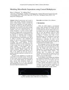
For the mesh quality estimate we can use the command meshqual where “1” means the best element and “0” the worst distorted element into a triangle. In Figure 2 we can see how the best 25% elements are distributed in the tube.
Figure 2: Mesh quality analysis — best 25 % elements
Solution of the Problem Because there are some difficulties during the computations with nearly incompressible materials there will be used the mixed formulation approach, where the the hydrostatic pressure acounting for incompressibility become as a new unknown. There is used parametric solver in the COMSOL Solve Parameters. We were faced to problems with convergence, therefore we have used the implemented numerical method for linear system solution UMFPACK, which is the most stable direct solver for our problem. For more quick analysis of the system of equations we choose “Matrix nonsymmetry” and nonlinear kind of the problem.
3
Results
Performing the inflation experiments we act with pressure onto the inner tube wall in radial direction. The outer wall and the basis are without any loads. We can see the inflation test results in Figures 3 and 4. In this experiment we have two hollow cylinders, the first one without the fibers (Figure 3) and the second one with the fibers (Figure 4).
We can observe how depends a change of radial displacement on the tube stiffenig. We consider identical amount of the pressure for both of the cases. The radial displacement urad of the second one is not so big as for the first tube which is not so rigid.
Figure 3: Numerical experiments on blood vessel — inflation test for p = 0.024P a and γ = 0
Figure 4: Numerical experiments on blood vessel — inflation tests for p = 0.024P a and γ = 0.5
4
Conclusion
During the work we were faced to many problems with convergence which have been risolved and stabled with COMSOL Multiphysics very well. Using this program we have appreciated friendly interface for our work with geometry, equations and results. COMSOL is a very good instrument for analysis of non-linear elasticity problems.
References [1] Beatty, M.F., 1987. Topics in Finite Elasticity: Hyperelasticity of Rubber, Elastomers and Biological Tissues With Examples. Appl. Mech. Rev. 40, 1699–1734. [2] COMSOL Multihysics, August 2006. COMSOL Multiphysics User’s Guide. Version: Comsol 3.3. [3] Podio-Guidugli, P., 2000. A Primer in Elasticity. Kluwer Academic Publishers. [4] Spencer, A.J.M., 1984. Continuum Theory of the Mechanics of Fibre-Reinforced Composites. Springer-Verlag, Berlin Heidelberg. Prof. Paola Nardinocchi Universit`a degli Studi di Roma La Sapienza, Facolt`a di Ingegneria, Dipartimento di Ingegneria Strutturale e Geotecnica, Via Eudossiana 18, 00184 Roma, tel.: +39 064458 5242, email:
[email protected] Ing. Tom´aˇs Svatoˇ n University of West Bohemia in Pilsen, Faculty of Applied Sciences, Department of Mathematics, Univerzitn´ı 22, 306 14 Pilsen, e-mail:
[email protected] Dott. Luciano Teresi Universit`a degli Studi Roma Tre, Facolt`a di Ingegneria, Dipartimento di Strutture, Via Corrado Segre 6, 00146 Roma, tel.: +39 065733 6378, e-mail:
[email protected]