Verifying Multiparty Call in ATM UNI Signalling Protocol GORDAN JEZIC and IGNAC LOVREK Department of Telecommunications University of Zagreb Faculty of Electrical Engineering and Computing, Unska 3, HR-10000 Zagreb CROATIA {gordan.jezic, ignac.lovrek}@fer.hr, http://www.tel.fer.hr/{jezic, lovrek} GIRISH BHAT Make Systems 4000, Regency Parkway, Suite 150 Cary, NC 27511-8502 USA
[email protected] Abstract: - This paper presents formal specification and verification of the multiparty call in ATM UNI signalling protocol. The protocol specification is written in the CCS process algebra (Calculus of Communicating Systems). Verification is done by using the NCSU-Concurrency Workbench. Due to the complexity of the protocol, the model is decomposed into three components. The protocol is verified by the model-checking feature of the Workbench. Each of its components is checked for safety and liveness properties using temporal CTL (Computation Tree Logic) and modal mu-calculus logic. Key-Words: - formal specification, model checking, verification, ATM signalling protocol, process algebra
1 Introduction
A typical protocol development process involves two phases: the specification and design phase in which a high level design of the protocol is specified using a partially formal protocol description language and an implementation phase in which the high level description of the protocol is translated to an implementation which is tested extensively for bugs. The bugs in the final implementation could appear either because of implementation errors or design errors. Implementation errors can be found easily. Design errors, however, are not only subtle and hard to trace, but also quite exspensive to correct as they require going back to the design phase. Therefore, it is necessary to apply techniques that detect errors early in the design phase. One solution to this problem is to use rigorous formal methods in the design process. This paper presents formal specification and verification of the multiparty call in ATM UNI signalling protocol. The protocol specification is written in the CCS process algebra (Calculus of Communicating Systems). Verification is done by the NCSU-Concurrency Workbench [4, 5]. The model of the protocol includes the
specification of the procedures for point-tomultipoint connections and model includes three users: one calling and two called users. Two users enjoy the same rights: both can initiate the basic call (point-to-point) and have of a third party join the call. Due to the complexity of the protocol, the model is decomposed [8-10] into three components. The first one covers all procedures for point-to-point call. The second includes the procedures for a pointto-multipoint call without clearing point-to-point connection. In that case, after setting up a point-topoint connection, only one additional user can be added to the connection. These two components represent two possible “flows” of the protocol, because after establishing a point-to-point connection, it is possible either to release a point-topoint call or to connect a new party to it. The third component consists of the procedures for a point-topoint and a point-to-multipoint connection with a restriction to one passive user. A passive user can only be a called user. The third component includes one calling, one called and one added user. Thus, the relations between the first two components are checked: the procedures of releasing a point-to-point call with the procedures for connecting and
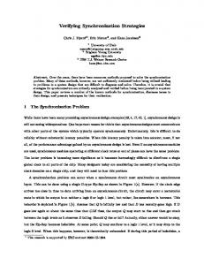
The procedures for establishing and clearing of a multiparty call are defined by the User-Network Interface (UNI 3.1) signalling protocol [1]. It is assumed that there are three users or ATM endstations, each connected to the ATM network through a user network interface (UNI). Two users participate in a point-to-point call and a third one can join the connection at the request of the calling (root) user (Figure 1). The UNI has two components: one defines the control procedures for the user side (USI) and the other defines the control procedures for the network side (NSI). The USI and the NSI are assumed to be connected by means of a reliable network and that the underlying ATM network is also reliable and error-free.
UNI
NSI2
NSI1
User2
UNI
User1
ATM
USI1
(1) (3) (8)
network (2) (7)
NSI3
User1
(4) (5) (6)
local user
2 Model Description
USI1
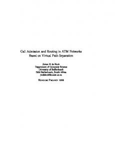
additional user (party) can be added to the connection by an ADD_PARTY request from the calling user. A party may be connected to or disconnected from a multiparty call at any time after the connection is established. A party can be added to an existing point–to-point connection only via the calling user who issues an ADD_PARTY message, or be dropped from a connection at the request of either the calling user or himself (but not by the other user). A typical execution sequence for a successful addition of a third party to an already existing (point-to-point) call is as follows (Figure 2).
NSI1
disconnecting an added user. The protocol is verified by using the modelchecking feature of the Workbench. Each component of the protocol is checked for safety and liveness properties using the temporal CTL (Computation Tree Logic) and the modal mucalculus logic. The paper is organised in the following way. Informal description of the model, model architecture and message flows for successful establishing and clearing of a multiparty call are presented in Section 2. Formalization of the protocol, components of the model as well as model assumptios are desribed in Section 3. Decomposition of the protocol and verification results are reported in Section 4. Conclusions are given in Section 5.
USI2
NSI3 UNI USI3 User3
Fig. 1: Architecture of the model A multiparty call is set up by first establishing a point-to-point connection between a calling and a called user. After this set up is complete, an
ADD PARTY CALL PROCEEDING SETUP CONNECT CONNECT ACKNOWLEDGE ADD PARTY ACKNOWLEDGE
User3 USI3 local user
(1) (2) (3) (4) (5) (7) (6) (8)
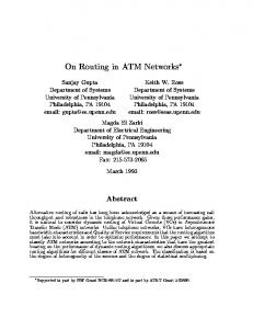
Fig. 2: Message flow for successful addition of a party The term User refers to the combination of a local user and the USI. A calling user initiates the addition of a new user (party) and sends an ADD_PARTY request to the NSI1. Index 1 refers to a calling side, index 2 to a called side and index 3 to a added (party) side. The NSI1 forwards the request across the network and sends a CALL_ PROCEEDING message back to the calling user. When the NSI3 (party side) receives the request, it forwards the request to the party as a SETUP message. If the party responds with a CONNECT message, the NSI3 responds with a CONNECT_ ACKNOWLEDGE message and sends a CONNECT message to the NSI1. The NSI1 then sends an ADD_PARTY_ACKNOWLEDGE message to the calling user. When the calling user receives this message, the multiparty call is established. An execution sequence for dropping of a party from an existing multiparty call by the calling user is as follows (Figure 3). The calling user indicates dropping of a party out by sending a DROP_PARTY message, which is forwarded by the NSI1 to the NSI3. The NSI3 sends a RELEASE message to the party. The party responds
with a RELEASE_COMPLETE message and when the calling user receives the DROP_PARTY_ ACKNOWLEDGE message, the clearing of the party is done.
(3)
(2)
NSI3
USI1
network
(1) NSI1
User1
(4)
User3 USI3
(5)
local user
DROP PARTY DROP PARTY ACKNOWLEDGE RELEASE RELEASE COMPLETE
local user
(1) (2) (3) (4) (5)
Fig. 3: Message flow for dropping of a party out
3 Formal Description
Formal model of establishing and clearing of a multiparty call is written in the process algebra CCS (Calculus of Communicating Systems) [2, 3]. The terms in it are described by the following grammer (1). P :: = nil | α.P | (P + P) | (P | P) | P[f] | P \ L | proc C =P (1) “.” represents the prefixing opeator; “+” is the summation of choice operator; “|” is the parallel composition operator; “f” is a relabelling function; “\” is the restriction operator, and “proc = “ is used for defining a processes. The model consists of 13 processes or components which are executed simultaneously; therefore they are connected by a parallel compostion operator. The model is added to the model for establishing and clearing a point-to-point call [7]. Given that only a calling user can add a party to the call, the model of a multiparty call must distinguish a calling and a called user. In this case, the model consists of three users. Two users have the same rights and both of them can initiate the point-to-point call and then can realise the multiparty call. A third user is a party user and can be only an added user. Thus, after establishing a point-to-point call, a calling user can either clear the call or initiate the procedures for establishing the multiparty call. If a calling user clears a point-topoint call, the model returns to the starting state. In the other hand, after having added a party to the call, either a calling or an added user can disconnect a
party. To establish a multiparty call, the model must have the following components: 1. the models of the local party, local calling and local called user, 2. the models of the USI on the party side, calling side and called side, 3. the models of the NSI on the party side, calling side and called side, 4. the models of UNI channels (between USI and NSI) on the party side, calling side and called side, and the network channels. The components (models) of the calling and called side are equal these users having the same rights. The model includes the following simplifying assumptions: 1. The channels are formalized as one-place buffers and all of them are reliable and errorfree, 2. The contents (information elements) of a message are ignored, 3. The model includes point-to-point and point-tomultipoint calls, multipoint-to-multipoint calls are not considered and “calls” and “connections” are equivalent, 4. The model does not include timeouts and retransmissions.
4 Protocol Verification
This section presents some verification results. Verification is based on two important properties of the protocol: freedom from the deadlock and liveness. The first property is checked for the safety of the protocol. Checking of the second one proves that if nothing bad happens, a connection will be eventually established. The properties are verified using the model-checking feature in the Concurrency Workbench.
4.1 Model Decomposition
Due to complexity of the protocol, the model is decomposed into the following three components: 1. procedures for establishing and clearing of a point-to-point call, 2. procedures for establishing of a point-to-point call with the procedures for adding and dropping of a party, 3. procedures for establishing and clearing of a multiparty call with a restriction to one passive user in a point-to-point call. The reason for protocol decomposition is a lack of memory and time wastage, given that over 40000
states and transitions are checked. Decomposition of the model will be presented by messages which are important in particular components (key messages). The model for establishing and clearing of a multiparty call with the corresponding messages is shown in Figure 4.
ATM network User2
User1
ATM network User2
User1
SETUP1 RELEASE1 ADD PARTY1 DROPPARTY1
possible “flows” of the protocol, because after establishing a point-to-point connection, it is possible either to release a point-to-point call or to add a party to the connection.
SETUP2 RELEASE2 ADD PARTY2 DROP PARTY2
(+) (+) (+) (+)
(+) (+) (+) (+)
SETUP1 RELEASE1 ADD PARTY1 DROPPARTY1
(+) (-) (+) (+)
User3
User3 RELEASE3
SETUP2 RELEASE2 ADD PARTY2 DROP PARTY2
(+) (-) (+) (+)
RELEASE3
(+)
Fig.6: Key messages of the second component
(+)
Fig. 4: Key messages for a multiparty call Two users establish a point-to-point call (SETUP1 and SETUP2) after which a calling user may clear the call (RELEASE1 or RELEASE2) or initiate the procedures for adding a party (ADD_PARTY1 or ADD_PARTY2). Having added a party to the connection, a calling user or a party can initiate the procedures for dropping the party out (DROP_ PARTY1 or DROP_PARTY2 and RELEASE3). The first component covers all procedures for establishing and clearing of a point-to-point call (Figure 5). This component is chosen naturally, because all actions for a multiparty call are connected on point-to-point call.
There are two users that can establish (SETUP) a point-to-point call and after that a calling user can add (ADD_PARTY) a third user (party), but can not clear a point-to-point call (RELEASE). After adding the party, the procedures of dropping the party can initiate the party out (RELEASE) or the calling user (DROP_PARTY). Third component consists of the procedures for a point-to-point and a point-to-multipoint connection with the restriction to one passive user. In Figure 7 User2 is passive user and can be a called user only. This component defines the interrelations between the first two components and thus the procedures for clearing of a point-to-point call (RELEASE) with the procedures for establishing (ADD_PARTY) and dropping a party out (DROP_ PARTY) are checked.
ATM network
SETUP1 RELEASE1 ADD PARTY1 DROPPARTY1
ATM network
User2
User1
SETUP2 RELEASE2 ADD PARTY2 DROP PARTY2
(+) (+) (-) (-)
(+) (+) (-) (-)
User3 RELEASE3
(-)
Fig.5: Key messages of the first component There are two users that can establish (SETUP) and clear (RELEASE) point-to-point call. A party is not included. The second component includes the procedures for establishing and clearing of a multiparty call without clearing a point-to-point connection (Figure 6). In that case, after setting up a point-to-point connection, only a party user can be added to the connection. These two components represent two
User2
User1
SETUP1 RELEASE1 ADD PARTY1 DROPPARTY1
SETUP2 RELEASE2 ADD PARTY2 DROP PARTY2
(+) (+) (+) (+)
(-) (-) (-) (-)
User3 RELEASE3
(+)
Fig.7. Key messages of the third component There are three users: User1 is a calling user, User2 is a called (passive) user and User3 is a party. After establishing of a point-to-point call (SETUP1), a calling user can clear this call (RELEASE1) or add a party to the connection (ADD_PARTY1).
4.2 Model Checking
The properties (deadlock and liveness) are specified in a temporal logic, known as the modal mu-calculus [6]. The syntax of mu-calculus is given by the following grammer (2): Φ :: = tt | ff | X | ¬Φ | Φ \/ Φ | Φ /\ Φ | Φ | [α]Φ | νX.Φ | µX.Φ (2) The formula tt holds of every state, whereas the formula ff holds of no state. The formula Φ1 \/ Φ2 holds of a state if either Φ1 or Φ2 hold of the state; likewise Φ1 /\ Φ2 holds of a state if both Φ1 and Φ2 hold of the state. α refers to actions. and [] are referred to as path modalities. The modal formula Φ holds of a state if the state has some αderivative at which Φ holds, and [α]Φ holds at a state if all α-derivatives of the state satisfy Φ. ν represents the greatest fixpoint operator (max) and µ represents the least fixpoint operator (min). The mu-calculus is extended to include the CTL (Computation Tree Logic) operators [6]. The CTL formulas and corresponding mu-calculus translations that were used in the verification (3, 4): AG prop max X = prop /\ [-{}]X
(3)
A (prop1 U prop2), min X prop2 \/ (prop1 /\ [-{}]X /\ tt) (4) Intuitively, A means that the property should hold for all computations, G means “always” and U means “until”. Each component of the protocol is checked for safety (deadlock freedom) and liveness properties. The first property says that the protocol is free of deadlocks. The following mu-calculus formula expresses this property (5): can_deadlock = min X = [-{}]ff \/ X
(5)
The second property requires introducing some new visible actions in the model. These actions are used for checking of the model behaviour and the model progress as expected. The new models for the local User1 and User2 (these models are the same) and added User3 are shown in Figure 8 and Figure 9. The visible actions are bolded. Each component includes only its visible actions, characteristic for this component, which are interesting for checking. In this case, for each component some corresponding property is being checked. With respect to that, it is defined a macro (6) with parameters a, p1 and p2 which says that on
all paths after an action a eventually a state satisfying p2 occurs and until then every state satisfies p1. proc NullUser1 = 'setup_req1.setup_request1.(setup_conf_USI1. NullAddPParty1 + setup_err_USI1.setup_error1.NullUser1) + setup_ind_USI1.('setup_resp1.setup_response1. ActiveUser1 + 'setup_err1.setup_error1.NullUser1) proc ActiveUser1 = rel_ind_USI1.'rel_resp1.NullUser1 proc NullAddParty1 = 'add_req1.add_request1.(add_conf_USI1. add_confirmation1.ActiveAddParty1 + add_err_USI1.add_error1.NullAddParty1) + rel_req1.release_request1.rel_conf_USI1. NullUser1 proc ActiveAddParty1= 'drop_req1.drop_request1.drop_conf_USI1. NullAddParty1 + drop_ind_USI1.'drop_resp1.NullAddParty1 Fig. 8: Model of a local user (User1 and User2) proc NullParty3 = setup_ind_USI3.('setup_resp3.setup_response3. ActiveParty3 + 'setup_err3.setup_error3.PocDodKor3) proc ActiveParty3 = rel_ind_USI3.'rel_resp3.NullParty3 + 'rel_req3.release_request3.rel_conf_USI3. PocDodKor3 Fig. 9: Model of a party (User3) liveness (a, p1, p2) = AG ([a] (A(p1 U p2)))
(6)
In the first component, a liveness of the procedures for establishing (7) and clearing (8) of a point-to-point call are checked. prop liveness_setup = liveness (setup_request1, ([setup_error1]ff /\ [setup_error2]ff), tt) (7) prop liveness_release = liveness (setup_response2, ([setup_request1]ff /\ (8) [setup_request2]ff), tt)
In the second component, liveness of the procedures for adding (9) and dropping (10) of a party and a liveness of the procedure for establishing of a pointto-point call (7) too are checked. prop liveness_add = ([add_error1]ff /\ liveness (add_request1, [setup_error3]ff), tt) (9)
References: [1] The ATM Forum, ATM User-Network Interface (UNI) Specification, Version 3.1, Prentice-Hall International, 1995.
prop liveness_drop = liveness (add__confirmation1, ([add_request1]ff U, tt \/ tt (10)
[3] Milner, R., Communication and Concurrency, Prentice-Hall International, 1989.
In addition checking (7) and (8), the third component includes checking of liveness when a calling user can concomitantly add a party or release a point-to-point call (11) (interrelation between first two components). prop liveness_add_release = ([add_error1]ff /\ liveness (setup_response2, [release_request1]ff), tt) (11) For example, the formula (9) says that if after add_request1 nothing bad happens (i.e. events add_error1 and setup_error3 do not occur), a setup_response3 takes place. For the last property the model had 8833 states and 30186 transitions. Verification of the properties took about 3 minutes on a SUN Ultra 1 workstation with 256 Mbytes of memory.
5 Conclusion
Formal specification and verification of the multiparty call in ATM UNI signalling protocol are reported. The specification is written in the CCS process algebra and verification is done by using model-checking feature of the Concurrency Workbench. Due to complexity of the protocol, the model is decomposed into three components and each is checked for safety and liveness properties using temporal logic CTL and modal mu-calculus logic. In the protocol design, there was a constant interaction between the modelling and verification phases. Therefore, in reality, the border between these two phases is being lost. Further studies would be a more detailed modelling including timeouts and retransmissions, modelling of more complex protocols with more users, possibility of negotiations and mobile agents.
[2] Milner, R., A Calculus of Communicating Systems, Springer-Verlag, 1980.
[4] Cleaveland, R., Parrow, J., Steffen, B., The Concurrency Workbench: A Semantics-Based Tool for the Verification of Concurrent Systems, ACM Transactions on Programming Languages and Systems, January 1993., Vol. 15, No. 1, pp. 36-72. [5] Cleaveland, R., Sims, S. T., Generic Tools for Verifying Concurrent Systems, Proceedings of the 2nd International Workshop on Applied Formal Methods in System Design, Zagreb, June 1997., pp. 3-8. [6] Cleaveland, R., Sims, S., The Concurrency Workbench of North Carolina, User’s Manual, September 1996., North Carolina. [7] Bhat, G., Cleaveland, R., “Verifying the ATM UNI 3.1 Signalling Protocol, Personal communication, 1997. [8] Holzmann, G. J., Protocol Design: Redefining the State of the Art, IEEE Software, January 1992, pp. 17-22. [9] Lin, F. J., Liu, M. T., Protocol Validation for Large-Scale Applications, IEEE Software, January 1992, pp. 23-26. [10] Hailpern, B. T., Owicki, S. S., Modular Verification of Computer Communication Protocols, IEEE Transactions on Communications, January 1983., Vol. 31, No. 1, pp. 56-68.