352
IEEE TRANSACTIONS ON VERY LARGE SCALE INTEGRATION (VLSI) SYSTEMS, VOL. 9, NO. 2, APRIL 2001
A Physical Design Tool for Built-In Self-Repairable RAMs Kanad Chakraborty, Member, IEEE, Shriram Kulkarni, Mayukh Bhattacharya, Pinaki Mazumder, Fellow, IEEE, and Anurag Gupta, Member, IEEE
Abstract—In this paper, we present the description and evaluation of a novel physical design tool, BISRAMGEN, that can generate reconfigurable and fault-tolerant RAM modules. This tool, first proposed in [3], designs a redundant RAM array with accompanying built-in self-test (BIST) and built-in self-repair (BISR) logic that can switch out faulty rows and switch in spare rows. Built-in self-repair causes significant improvement in reliability, production yield, and manufacturing cost of ASICs and microprocessors with embedded RAMs. Index Terms—Built-in self-testing (BIST), die cost, reliability, self repair, yield.
I. INTRODUCTION
I
N the 1980s, the field of VLSI testing witnessed remarkable growth. As the chip size has grown phenomenally to more than a million transistors per chip, the complexity of testing chips has increased, more and more subcircuits have become inaccessible for testing due to the diminishing pin-to-device count, and physical design has become considerably more complex and time-consuming. Built-in self-test (BIST) was introduced for various structured logic and memory arrays, to allow comprehensive testing for functional, electrical, and parametric faults. BIST circuits ensure that bad chips will be automatically spotted and eliminated on the production line, thus ensuring quality control. However, in the 1990s, the growth of the VLSI industry has been even more spectacular, ushering in sophisticated nanofabrication technology for manufacture of complex VLSI chips (such as microprocessors, DRAMs, etc.) using several million transistors. Deep submicron CMOS processes are associated with peculiar defect mechanisms that cannot be comprehensively tested using traditional “stuck-at” type tests. As effective channel lengths of transistors shrink below 0.12 m, even minor process variations across the surface of a silicon wafer can cause layout defects [10], [11]. Even though such defects are not always associated with immediate functional failure, they may lower the reliability and diminish the operational life-span of the chip if left unrepaired for a long time (for example, by causing the chip to drain a large amount of current). To improve the yield and reliability of VLSI chips, BIST alone is not sufficient; built-in self-repair (BISR) is of growing importance. FurtherManuscript received February 24, 2000; revised July 14, 2000. K. Chakraborty is with the EDA Laboratory, IBM T. J. Watson Research Center, Yorktown Heights, NY 10598 USA (e-mail:
[email protected]). S. Kulkarni, M. Bhattacharya, and P. Mazumder are with the Department of Electrical Engineering and Computer Science, The University of Michigan, Ann Arbor, MI 48109 USA (e-mail: shriram/mayukh/
[email protected]). A. Gupta is with the Enterprise Processor Division, Intel Corporation (SC12506), Santa Clara, CA 95052 USA (e-mail:
[email protected]). Publisher Item Identifier S 1063-8210(01)01496-2.
more, BIST and BISR are essential in improving the testability and repairability of RAMs used as embedded memories (such as instruction and data caches of high-performance microprocessors, embedded memories in ASICs used in digital cameras and cellular modems), or in mission-critical space, oceanic, and avionic applications where external field testing and repair are prohibitively expensive or infeasible. RAM compilers were introduced in 1986 by Texas Instruments [23]. The first reported compiler, called RAMGEN, generated layouts, simulation models, symbols and datasheets (for setup and hold times, read access times and write times, and supply currents and voltages) for RAMs, ROMs, and PLAs. Since this effort, RAM compilers have become progressively more powerful and sophisticated. CMOS SRAM compilers have been designed by Motorola and Mentor Graphics (the Memorist compiler [24]), Cascade Design Automation (the CDA RAM compiler [19]), and at the University of Michigan (the Aurora GaAs MESFET RAM compiler (ARC) [4]). Some of these compilers, such as the CDA and the ARC, try to achieve process independence; that is, the ability to generate layouts for any input process technology and set of design rules. In 1992, Kebichi et al. [8] reported a RAM compiler for built-in self-testable RAMs. In this paper, we describe a physical design tool, BISRAMGEN, for built-in self-repairable static RAMs. BISRAMGEN is design-rule independent and can generate efficient layouts and simulation models for built-in self-testable and built-in self-repairable RAM arrays. It achieves low area overheads for BIST and BISR, of at most 7% for realistic array sizes for embedded RAMs. We have examined a wide range of microprocessors spanning almost a decade and have observed that realistic array sizes for embedded memories used as internal caches range between 64 Kb and 4 Mb. For example, the embedded Level Two (L2) cache used inside a recent Pentium III Xeon processor introduced on March 17, 1999, is 256 kbyte ( 2 Mb) (as documented in http://www.intel.com/pressroom/kits/processors/quickreffam.htm), and the internal Level One (L1) cache used inside a recent AMD-K6-III processor is 64 kbyte ( 512 Kb) (see http://www.amd.com/products/cpg/k6iii/techfeatures.html). Our calculations show that built-in self-repair achieves significant improvement in production yield and reliability and lowers the manufacturing cost of dense ASICs and microprocessors with embedded RAMs. II. OVERVIEW OF BISRAMGEN Fig. 1 gives an overview of the layout synthesis and simulation model generation of BISRAMGEN. From a set of user-
1063–8210/01$10.00 © 2001 IEEE
CHAKRABORTY et al.: PHYSICAL DESIGN TOOL FOR BUILT-IN SELF-REPAIRABLE RAMs
Fig. 1.
353
Overview of BISRAMGEN.
specified geometry parameters and the CMOS technology data, BISRAMGEN builds a library of leaf cells that are subsequently used for generating modules or macrocells in a bottom-up (hierarchical) fashion to complete the overall layout. The user needs to specify a CMOS process before invoking BISRAMGEN. A range of 3-metal processes with feature widths in the range of 0.5 m and above, such as the Cascade Design Automation processes CDA.5 3m1p and CDA.7 3m1p, and the MOSIS process mos.6 3m1pHP, may be chosen by the user. When invoked, BISRAMGEN allows the user to input the values of the circuit parameters for a wide-word RAM employing column-multiplexed addressing. As shown in Fig. 2, in column-multiplexed addressing, a single column stores multiple bits, the number of bits per column being . The number of bits per memory word is denoted by . A log -tocolumn decoder chooses denoted by bitline pairs from each of I/O exactly one out of -bit word. The parameters explicitly subarrays, producing a , , number of words, specified by the user include: number of spare rows (4, 8, or 16), size of critical gates in the RAM circuitry, and the strap space (i.e., the spacing must between subarrays at regular intervals). The value of be a power of 2. Critical components in the RAM circuitry, such as the precharge transistors and the word line drivers, are made larger than minimal size to increase their current and drive strengths. Moreover, for a given gate size, the transistors are automatically sized to balance the rise and fall times. This is made possible by built-in access to SPICE utilities. The strap space parameter provides design flexibility in increasing the spacing between subarrays at regular intervals. This may be required for various reasons; for example, to
allow over-the-cell wiring across the RAM array to save silicon area. Note that BISRAMGEN is not designed to build a RAM array to meet a user’s timing, power and/or area specifications. Rather, it can generate simple leaf cells ahead of time and extract and simulate them, thereby extrapolating and providing timing, area, and power guarantees for the overall system before designing the overall layout. If the user is unsatisfied with these guarantees, BISRAMGEN will attempt to build the layout using any user-provided building blocks (e.g., user-specified library of leaf cell and custom RAM designs). However, this process is not guaranteed to complete successfully in one pass and the layout generation may require varying degrees of manual intervention by the layout designer. The characteristics of BISRAMGEN that make it attractive to a CAD designer are as follows. 1) Efficient Place-and-Route combined with structured custom design: BISRAMGEN exploits the array-like regularity in module functions and interconnections to build the macrocells: RAM array and peripheral circuitry such as sense amplifier and row and column decoder arrays, DATAGEN (test data generator), ADDGEN (test address generator), TLB (BISR circuit), TRPLA (for storing the control program), and STREG (state register). During this structured design, no routing is necessary and the signals in adjacent modules are perfectly aligned and connected by abutments between macrocells. Hence, signal propagation delays between modules are minimal. To complete the routing phase, BISRAMGEN uses an efficient algorithm for macrocell place-and-route. It sorts the rectangular macrocells in decreasing order of areas and uses heuristics to make the overall layout “as
354
Fig. 2.
IEEE TRANSACTIONS ON VERY LARGE SCALE INTEGRATION (VLSI) SYSTEMS, VOL. 9, NO. 2, APRIL 2001
Column multiplexed addressing in RAMs.
rectangular as possible.” Some of these heuristics are as follows. a) Port alignment: Suppose I/O ports of a macrocell need to be connected to I/O ports of another and that these ports are present on macrocell one edge of each macrocell. Then and will be placed such that these two edges face each other with the corresponding ports in alignment. Using this heuristic has two advantages: i) it improves routability and interconnect lengths between and and ii) it avoids the long computation involved in trying out all 64 pairs of orientations between and . This heuristic contributes to the overall rectangularity of the layout. b) Stretching: Sometimes, one macrocell may need to be stretched relative to another so as to cause better port alignment between the two macrocells, thereby decreasing interconnect lengths by causing all or most of the ports to be connected by abutments. The layout generation quality is provably -optimal (which means that the layouts differ from optimal by a , for a fixed, “small” that does not factor of depend on the size of the memory array). For proof of this, see [2]. It tries to reduce timing delays by a clever placement strategy that brings ports to be connected close together and often uses over-the-cell routing with third metal, instead of channel or global routing, to reduce the interconnect lengths and delays. A CAD designer using BISRAMGEN can complete the BISR-equipped RAM
module generation without switching between tools and can thereby achieve a lower turnaround time and a high-quality design. 2) Solution Quality: The area overheads with BIST, BISR, and redundant rows is less than 7% for all realistic RAM array sizes. The BISR technique used achieves a very tiny delay (that can be easily masked by circuit techniques) on the RAM access time and produces significant improvements in chip yield, reliability, and cost. III. CRITICAL EXAMINATION OF OTHER EXISTING BIST/BISR RAM IMPLEMENTATIONS A RAM generator was described by Kebichi and Nicolaidis [8] for RAMs equipped with BIST and transparent BIST, i.e., BIST techniques that result in the normal-mode contents of the RAM to remain unmodified at the end of the self-test. Their approach does not include self-repair. A built-in self-repair scheme was proposed by Sawada et al. [17] in 1989. This was a very simple scheme based upon the address comparison method; that is, registering a failed address (in a fail address register) during test mode and comparing this address with an accessed address during normal mode. An address match would thereby indicate that the accessed address has faults and would cause access into a spare memory module. This scheme was originally designed to repair single address location faults, because only one faulty address location could be registered. Chen and Sunada [5] have extended this design to repair multiple faults and have also proposed a novel architecture to reduce the access time penalty, one of the main drawbacks
CHAKRABORTY et al.: PHYSICAL DESIGN TOOL FOR BUILT-IN SELF-REPAIRABLE RAMs
of the address comparison method. Hence their architecture is suitable for high-capacity SRAMs. Chen and Sunada [5] have used a hierarchical cell array organization to minimize the overall memory access time. Two salient features of their design are: having the self-test and selfrepair logic away from the critical data path to minimize delays and keeping the self-repair logic as simple as possible to minimize sensitivity to processing defects. In their design, the entire system is composed of a number of subblocks organized in an array structure. These subblocks are recursively decomposed into smaller and smaller subblocks until a level is reached where a flattened implementation of the word-oriented memory is better in terms of speed, area and ease of testability. The major part of the self-test and self-repair scheme is incorporated at the lowest level of the hierarchy. Self-test is carried out at this level. The test algorithm used is IFA-13 [18] that includes a functional test followed by a data retention test. The main components of this lowest level organization are briefly explained. 1) Test Enable signal: This signal switches the memory from normal mode to the test/repair mode and vice versa. 2) Address and data generators: The address generator increments or decrements addresses in a sequential fashion during marches. The data generator generates data patterns to be stored in the memory. The inversion signal from the clock generator causes either the data pattern or its complement to be stored. 3) Addresscorrectionblock:Duringtheself-test,theaddress generated by the address generator is sent to the addresscorrection block which passes it directly to the address decoder. After a fault or defect has been diagnosed and the system switches back to normal operational mode, any incoming address intended for a faulty memory location is diverted to a new address by the address-correction block. 4) Fault signature block: The word patterns written into and subsequently read out from the memory are compared with the original word patterns. Any discrepancy causes a pulse on the capture signal. Such a pulse activates the fault signature block, which captures the memory address where the error occurred. This circuit, which contains two fault capture blocks, is capable of storing and repairing at most two faults at different address locations. 5) Redundant memory locations and the fault assembler: Redundant memory locations are introduced at different levels of the hierarchy and the BISR scheme can repair at most two faulty addresses in each subblock. Failure to repair a subblock results in exclusion of the subblock from the system using fault-tolerant logic (called fault assembler), implemented at the top level, to divert accesses from dead blocks to functional blocks. BISRAMGEN offers several attractive advantages over the above approach. 1) In Chen and Sunada’s scheme, there is no discussion of the delay penalty. In fact, although their hierarchical decoding scheme will alleviate the penalty by pushing it down to the lowest level of the hierarchy, the address correction and fault signature blocks will still cause a
355
small penalty on the RAM access time. This is because of the fact that during normal operation, the incoming address is compared sequentially, instead of in parallel, with the two addresses stored in the two fault capture blocks. Their scheme is, therefore, impractical for embedded memories used inside modern high-speed microprocessors. BISRAMGEN, which uses a very fast, parallel comparison of the incoming address with a set of stored faulty addresses, produces a very tiny delay penalty if 4 spare rows are used. This penalty can easily be masked using circuit techniques, described later. 2) Chen and Sunada’s scheme is practical only with a hierarchical decoding scheme. If hierarchical decoding is not used, their approach requires modifications for becoming practical. 3) Chen and Sunada’s scheme provides the capability of repairing only two faulty addresses in each subblock. BISRAMGEN affords a much greater degree of fault tolerto faulty addresses in each subance of about block, assuming that the subblocks employ column-mulbits per column. tiplexed addressing with 4) The data generator used by Chen and Sunada applies a single data pattern or its complement on each memory word. The data generator built by BISRAMGEN implements a Johnson counter that allows multiple data backgrounds to be applied to the memory words, instead of only the all-0’s or the all-1’s patterns. This improves the fault coverage for coupling faults between bits of the same word. IV. CIRCUIT IMPLEMENTATION The RAM arrays built by BISRAMGEN employ circuit techniques for high speed and high bandwidth. Furthermore, they use a BIST scheme that guarantees comprehensive fault coverage. The various components of the BISR-RAM circuit are described as follows. 1) Column multiplexed addressing: To implement columnmultiplexing, the outputs of the column decoders are sent to pass-transistor multiplexers, which select one set of pairs. This scheme is illustrated in Fig. 2. Column-multiplexing improves the data bandwidth of memory devices, by increasing the number of bits accessible in a single cycle. This technique is thereby very useful for high-bandwidth requirements of embedded memories such as caches, multimedia memories, video RAMs, and application-specific memories in telecommunication ASICs. 2) Addressing logic: The regular rows of the RAM have row decoders. The address of a word stored in the RAM has two fields: row and column. The row address part is decoded by the row decoders to select a unique row. The column address part is decoded by the column decoders and then sent to the column multiplexers, described in the -bit word previous paragraph. As a result, a unique in a particular row is selected. In addition to the regular rows, the RAM array has redundant rows of memory cells. These redundant rows are fully integrated with the
356
IEEE TRANSACTIONS ON VERY LARGE SCALE INTEGRATION (VLSI) SYSTEMS, VOL. 9, NO. 2, APRIL 2001
Fig. 3.
Current mode sense amplifier design generated by BISRAMGEN.
main array and share the same column multiplexers. The address diversion to these redundant rows is achieved using a hardware translation lookaside buffer (TLB) that performs an extremely fast, parallel address comparison between the incoming address pattern and a set of stored address patterns, and selects a unique spare row and a multi-bit column. 3) Fast-access memory design: Fast memory access is achieved by using current-mode sensing, as shown in Fig. 3. In this technique, a minor current differential in and lines latches the sense amplifier. In write the mode, the sense amplifier is bypassed and the bit-lines are directly accessed.
V. BUILT-IN SELF-TEST CIRCUIT BISRAMGEN uses a low-area overhead, microprogrammed BIST circuit design for applying the IFA-9 test [18] on a static RAM array. The microprogrammed control unit is called Test and Repair Controller PLA (TRPLA). As the name indicates, it is a combined test and repair controller that is used for generating control signals in both BIST and BISR modes of operation. It is implemented as a pseudo-NMOS NOR-NOR PLA loaded with the control code. During layout synthesis of the BISR-RAM module, the control code is read in at runtime by BISRAMGEN from two input files (one for the AND plane, the other for the OR plane). Changing these files to implement a different test algorithm is a simple and straightforward matter.
In addition to TRPLA, the test circuitry consists of a Test Data Background Generator (DATAGEN) and a Test Address Generator (ADDGEN). The circuit can also send a signal to the processor to generate a reset state during which data retention testing is done. The test involves two passes. In the first pass, the memory array is tested and faulty addresses are stored in a translation lookaside buffer (TLB). In the second pass, the array is retested along with the mapped redundant addresses. Any fault detected in the second pass produces a “Repair Unsuccessful” status signal, which implies either too many faults in the memory array or faulty spares. This two-pass algorithm can be easily converted to a 2 -pass algorithm; that is, the cycle of self-testing and self-repair may be iterated to repair faults within the spares themselves. The march notation for the IFA-9 test is as follows [18]: , , , , , , Delay, . An important component of Delay, the IFA-9 test is data retention testing. The BIST circuit implemented by BISRAMGEN requires the intervention of the embedded processor for signaling the start and end of the waiting period for this test. During this period, the embedded processor tristates all the address, data and control lines for a fixed period of time (say 100 ms). After this duration, the control is passed back to the test controller. IFA-9 detects a wide range of functional faults caused by layout defects; for example, stuck-at and stuck-open faults, transition faults and state coupling faults. For a wide-word RAM, this test has to be repeated with multiple background patterns in order to test pairwise couplings between cells of the same word. To run this test, a binary up-down counter for address generation (ADDGEN) and a Johnson counter for background data generation (DATAGEN) are provided. The test address generator ADDGEN needs to generate a forward as well as a reverse addressing sequence. Consequently, it is implemented as a binary up/down counter. The test data generator DATAGEN is a Johnson counter that can data backgrounds for a -bit RAM word. generate words, as In reality, we need to generate only , follows: all-0, , all-1. However, the generation of background patterns in patterns, each word requires less hardware than that of and is thereby preferable, even though it causes a greater test application time. It is proved in [2] that a Johnson counter produces all the background patterns required. The test data generator DATAGEN not only generates background patterns, but also compares the read data with their expected values. Since each read data is the inverse of the immediately preceding write data (and vice versa) in the IFA-9 test, this -input comparison is done using exclusive-OR gates and a OR gate in a straightforward manner. VI. BUILT-IN SELF-REPAIR CIRCUIT The faulty row addresses detected by BIST are stored in a translation lookaside buffer (TLB). This circuit uses an innovative design that associates a sequence of faulty addresses with
CHAKRABORTY et al.: PHYSICAL DESIGN TOOL FOR BUILT-IN SELF-REPAIRABLE RAMs
a unique, predetermined, strictly increasing sequence of redundant addresses. These addresses are stored in the TLB during the first pass of the BIST. In the second pass, the incoming address is compared in parallel with all the stored addresses in the TLB. If a match is found, then an address diversion occurs to a redundant location. This approach causes both the regular and the mapped redundant locations to be tested comprehensively. The strictly increasing sequence of redundant addresses guarantees that provided enough spares are available, any faulty (nonspare or spare) row can be replaced. The TLB produces a modest delay penalty (of about 1.2 ns with four spare rows and a 0.7- m technology) for matching and mapping the incoming addresses during normal operation. This small delay, which is at least an order of magnitude smaller than the RAM access time, will not result in stretching of the RAM access time. This is due to the fact that the TLB operation can be completely masked or overlapped with other components in the read or write cycle. Some of the circuit techniques for functionally masking the TLB delay are as follows. 1) In case of an asynchronous RAM, it may be possible to overlap the TLB delay with the precharge phase following an address transition detection (ATD) signal of a read or write cycle (note: often RAM bit-lines are precharged in anticipation of read in order to reduce the access time, even though the actual operation may have been a write). 2) In case of a synchronous RAM with a level-sensitive address register, the address bits are sent simultaneously to the address register and the TLB, and the operations of the TLB (address comparison and issue of the spare address pattern) are done in parallel with those of the address register when the clock is low. When the clock is active, either the address selected by the TLB (in case of a “match”) or the address register output (in case of no match) is sent to the row and column decoders. This selection can be achieved using suitably sized tristate buffers at the outputs of the TLB and the address register. 3) It may be possible to compensate the TLB delay penalty by increasing the sizes of the devices used in the row and column decoders, so as to make the decoders slightly faster. This will result in masking the TLB delay at the expense of a greater power consumption by the decoders and a slightly greater silicon area. All these techniques rely on the fact that the TLB operation is extremely fast. This will happen provided 1–4 spare rows are to spare used, causing a redundancy of between words, which is large enough in practice. BISRAMGEN will allow a user to generate a RAM array with more spares but will not be able to guarantee that the TLB delay penalty can be masked. If a column is faulty, the row redundancy will be quickly swamped because every single word on a faulty column will be found to be faulty. Also, in the second pass of our BIST approach, a “Repair Unsuccessful” signal will be produced, since the redundant locations will also be faulty. Thus column failures can be detected but not directly repaired in our approach. In this research, we have examined high-speed high-bandwidth RAMs, built using very deep submicron technologies, that are used as embedded memories. The access times of such RAMs are of
357
the order of 1 to 2 ns, and these access times are very sensitive to even minor changes in the main array, for example, adding simple transistors or logic gates to the bit and word lines. For comprehensive column testing and fault diagnosis, pass transistors and latches need to be added to every single bit-line pair in the array and these circuits would cause significant deterioration of the RAM access time. Since our goal is to implement a self-repair solution that produces no access penalty on the RAM, we do not advocate the addition of column testing and repair circuitry to the RAM array. The self-test and self-repair controller consists of 59 states, encoded using six flip-flops, and a pseudo-NMOS NOR-NOR PLA. The controller area is found to be a very tiny fraction of the memory array area (less than 0.1%) for a 16-kbyte RAM. VII. YIELD IMPROVEMENT BISRAMGEN generates CMOS layouts of built-in self-repairable RAM arrays. The circuits synthesized can repair a maximum of faulty rows, being the number of available spare rows. A built-in self-repairable RAM produced by BISRAMGEN is said to be “good” if the manufacturer can guarantee that the spares are all good and the number of faulty words is at most equal to the number of spare words. Since BISRAMGEN is unable to perform more than one round of spare substitution (i.e., it is unable to substitute faulty spare words by fault-free spare words), we use the above notion of “goodness” of BISR’ed RAMs. Suppose we use the Poisson model of a single cell yield, i.e.,
where represents the average number of faults per cell. Let us also assume the well-known yield formula due to Stapper [21], [22] to calculate the original yield of the memory array without built-in self-repair
where is the defect density, is the area of the RAM array, and is some clustering factor of the defects. be the probability function for a defect pattern to be reLet pairable with respect to the fault-free spare rows available. Then is as follows: the yield
where
where denotes the area of the additional circuitry (BIST/BISR). -bit row The probability of not having a failing bit in a , and the probability that at least one bit fails is given by . A defect pattern can be repaired sucis given by cessfully if and only if the number of faulty rows is at most equal to the number of spare rows, and the spares required are themselves fault-free. Note that if some (but not all) spares are faulty, the RAM module may still turn out to be repairable if those
358
IEEE TRANSACTIONS ON VERY LARGE SCALE INTEGRATION (VLSI) SYSTEMS, VOL. 9, NO. 2, APRIL 2001
=4
=4
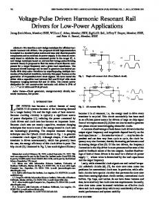
Fig. 4. Yield versus number of defects for a narrow RAM array with 1024 rows, bpc and bpw ; the Y -axis shows yields corresponding to four plots, as follows: (a) no spares (and no BISR); (b) 4 spares BISR; (c) 8 spares BISR; and (d) 16 spares BISR.
+
+
faulty spares are not used. However, since we require the RAM modules to be also repairable during field use, we adopt a stricter definition of “goodness” from the standpoints of both manufacturing yield and field reliability, namely, that all the spares should be fault-free. For a given number of defects and a single exponentially decreases with the product of memory cell, , , and ; it is proportional to . Let us assume that the defect density remains unchanged when we add BISR and redundancy to a RAM array. Fig. 4 displays the improvement in yield due to BISR for a RAM with . The axis denotes the 1024 rows, and with total number of defects injected into a nonredundant RAM array (i.e., the product “ ” in the equation for for a RAM without redundancy). For a RAM with redundancy and BISR, the total number of defects shown in the axis must be multiplied by the “growth factor” (i.e., the area of the redundant array with BISR divided by the area of the corresponding nonredundant array). For example, suppose a RAM array with BISR and four spares is 10% larger than the corresponding array with no BISR and no on the yield plot for this RAM array spares. Then a point (similar to the plots shown in Fig. 4) represents the yield when . the total number of defects injected into the array is Four yield plots are shown corresponding to: (a) no spares (i.e., ); (b) 4 spares with BISR; (c) 8 spares with BISR; and (d) 16 spares with BISR. Obviously, in cases (b)–(d), we are values. plotting the corresponding The BISR circuitry produced by BISRAMGEN is suitable for wide-word RAMs that are typically used as embedded macrocells within high-density microprocessors and application-specific integrated circuits (ASICs), for example, those used in telecommunication and local-area network applications. Almost all modern microprocessors have on-chip data and instruction caches or combined caches. In addition, some microprocessors use different levels of caches (called, L1 and L2
+
caches), such as Alpha® 21164. Some microprocessors, such as Motorola 68060, use a “branch cache” for storing branch prediction addresses. Therefore, it is necessary to analyze the yield improvement due to BISR not only for the RAM circuits themselves, but also for the entire chip that includes the RAM as an embedded component. The simplest model we can use to estimate the yield of a chip is the product of the yield of all the constituent macrocells, including the redundant RAM array with BISR. If a microprocessor includes macrocells excluding the RAM, the chip yield model is as follows:
In this model, we may lump together all the macrocells that are assumed to include no redundancy or self-repair, as done by Khare et al. [9], and analyze the yield of only the RAM. This approach, however, is complicated by two factors, namely: a) defects in the RAM layout may have global effects on the chip and b) if the chip area is limited, the effective area within the chip (i.e., the area available for placement and routing of the macrocells) is reduced as a consequence of BISR in other its caches, and this may impose layout constraints on the other macrocells. Commercial microprocessors that use on-chip redundant caches, such as SuperSPARC®, often have a large area overhead due to redundancy and the effective area may be as low as 73% [13]. Examples of problem a) are when a RAM layout defect causes a break in a global node or net of a microprocessor or GND lines, causing a fault that cannot be such as the repaired by any means within the RAM and that might produce global failure. Using simulation approaches with prototype CAD tools, Khare et al. [9] show that the critical area for these fatal flaws, plotted against the defect radius, may be either
CHAKRABORTY et al.: PHYSICAL DESIGN TOOL FOR BUILT-IN SELF-REPAIRABLE RAMs
very high (100 m or above) for all realistic defect radii or nonexistent for all realistic defect radii, depending on which of two possible RAM layout templates are chosen. BISRAMGEN implements the 6T SRAM cell layout that causes a near-zero critical area for these fatal faults. Hence, this problem of having fatal critical areas is very unlikely in BISRAMGEN-generated RAM layouts. The BIST/BISR area overhead as a percentage of the global chip area of commercial microprocessors is found to be less than 1.5%, with only a few exceptions (in one case it was seen to be as high as 3.3%); as a result, problem b) described above will not be encountered.
359
The RAM module will survive until time if and only if at of the regular words are faulty until time , and most spare words are themselves fault-free until this time. the be a random variable denoting the number of faulty Let of the built-in words at time . Then the reliability function self-repairable RAM module is as follows:
VIII. RELIABILITY IMPROVEMENT In this section, the word “failure” is used as a synonym for “hard”’ (or permanent) failure. Transient failures (i.e., failures due to transitions in system state such as startup or shutdown), temporary failures (such as those due to alpha particle hits, cosmic rays, static discharges, etc.) and intermittent failures (such as those caused by resistance and capacitance variations and crosstalk), affect the system for too short a duration to be detected and repaired by BISR techniques. We begin by recapitulating a few definitions. Definition 1: The reliability (also known as survivability) of a system as a function of time , is the probability of correct functioning of the system until time . Expressed mathematically
with and
(Note: In the above, is a random variable denoting the time denotes the probability at which a failure occurs, and .) that Definition 2: The failure probability density function, , is defined as the rate of decrease of reliability with time ; i.e., the negative derivative of . . Hence, Definition 3: The mean time between failures MTBF, also known as the mean time to fail MTTF, is defined as the expected value of the time at which failure occurs. . In other words, Integrating the above by parts, we conclude that: . (For example, if , then .) Suppose that a memory module generated by BISRAMGEN bits per column, consists of regular rows, spare rows, bits per words. Assume that the failure rate per bit and per unit time is . Then a single RAM cell is fault-free with . Therefore, the probability that a -bit a probability of , is as follows: RAM word is faulty at time , denoted by
The MTTF is computed by integrating the reliability function , from to infinity. The result is as follows:
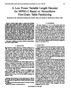
Evaluation of the reliability equation reveals that the reliability typically increases with the number of spares only after a period of several years after manufacture. Initially the reliability is found to decrease with the number of spares. Fig. 5 illustrates the reliability as a function of time (i.e., the age of the device), for a RAM with 1024 regular rows, . The defect rate per cell has been fixed at per kilo-hour. This plot indicates that the reliability increases with the number of spares only after a certain age of the device. Until this age, however, the reliability with more spares will be less than that with fewer spares. For example, the reliability with four spare rows is greater than that with eight spare rows until the age of the device becomes about 8 years (i.e., 70 000 h after manufacture). IX. AREA OVERHEAD BISRAMGEN produces low-area overhead BIST/BISR circuitry. Table I gives some examples of the area overhead including redundancies, BIST and BISR. In these tables, the pa( the number of words), , , and rameters used are: spares ( the number of spare rows), the geometries being spec. ified as Note that the redundant rows are not considered as overhead since redundancy is used in a vast majority of large RAMs (and in some cases, ROMs) even if there is no self-repair. In case there is no self-repair, the following techniques are commonly used for reconfiguration of RAMs and ROMs: a) electrically-programmable redundant elements [12] and b) laser-blown polysilicon or diffusion fuses [1], [7], [14], and c) electrically-blown programmable polysilicon fuses [6], [15], [20]. These techniques are difficult and/or too expensive to use for embedded memories. Even if we count the redundant rows as overhead, the fact that we have only 4 redundant rows in the array containing 512 or 1024 regular rows (see Table I), causes
360
IEEE TRANSACTIONS ON VERY LARGE SCALE INTEGRATION (VLSI) SYSTEMS, VOL. 9, NO. 2, APRIL 2001
Fig. 5.
Reliability for a RAM with BISR with a defect rate of 10
per kilo-hour per memory cell; the RAM has 1024 regular rows, with bpc = 4 and bpw = 4.
TABLE I BISR OVERHEAD
WITH FOUR SPARE ROWS, PROCESS ILLUSTRATION: CDA0.7U3M1P
CHOSEN
FOR
their contribution to be much less than 1% of the RAM array area without redundant rows. The BISR area overheads are found to be comparable with results published by other researchers, such as [5]. Most researchers base their results on either a custom layout or a very rough transistor count metric, and typically for one specific process technology. Since our results are based on BISR RAM layouts actually built for a wide range of commercial CMOS processes, we feel that they are very reliable. Note that the above area overhead translates to only about 1%ofthe total chip area, asobtained using die floorplan analysis for a range of microprocessors and ASICs [2].Typicallayoutplotsproducedby BISRAMGENareshownin Figs. 6 and 7. The sizes are respectively 64 and 128 kbytes, which are typical for embedded RAMs. X. COST IMPROVEMENT The basic manufacturing cost model (known as the MPR model [13]) that we can use is as follows: Manufacturing cost/chip
Die cost Test & Assembly cost Package & Final test cost
Fig. 6. SRAM array with 4 K words of 128 bits each (bpw ), 8 bits per column (bpc), 32 cells between strap, four spare rows and buffer size 2 (i.e., twice the minimum size).
As will be shown, in order to obtain the total cost of the packaged and tested microprocessor chips with and without built-in self-repairable on-chip caches, we need to modify the “die cost” component of the basic MPR equation. The components of the cost model are explained. 1) Cost per die: The type of process being used determines the wafer cost. The wafer cost can be obtained from sources of industrial data, such as [13]. The number of
CHAKRABORTY et al.: PHYSICAL DESIGN TOOL FOR BUILT-IN SELF-REPAIRABLE RAMs
Fig. 7. SRAM array with 4 K words of 256 bits each (bpw ), 16 bits per column (bpc), 32 cells between strap, four spare rows and buffer size 2.
dies-per-wafer can be easily calculated from the die area, assuming a 150-mm (6-in) wafer, or a 200-mm (8-in) wafer, as appropriate. Since wafers are circular and dies are rectangular, the larger wafers increase the wafer cost, but more than proportionately increase the number of dies-per-wafer. In particular, when we go from 150-mm (6-in) wafers to 180-mm (8-in) wafers, the wafer cost increases by about 50% but the number of dies-per-wafer increases by 80–100%, causing an overall cost improvement. Most of the recent microprocessors, such as IBM’s microprocessors, Intel, MIPS and SPARC processors are built on 200-mm wafers. The yield calculation for each die with and without built-in self-repair is done as described before. The die cost is then calculated as follows: Die cost
Wafer cost Dies per Wafer Yield
Note that in the above equation, the die contains the entire microprocessor circuit, including any on-chip cache. The yield per die, therefore, will be the product of the
361
yield values for the individual macrocells, such as Instruction Unit, Floating Point Unit, Instruction Cache, Data Cache, and so on. Improving the yield of the cache(s) by a factor of will therefore, also cause the overall die yield to improve by the same factor. Except the caches, all other macrocells are assumed to have no redundancy or fault-tolerance; hence, their yield values will be the same before and after the use of built-in self-repair for the cache. From the above equation, it can be easily seen that for a given process, the die cost is inversely proportional to the product of dies-per-wafer and the yield. Use of built-in self-repair slightly lowers the first factor (i.e., dies-perwafer) but significantly increases the second factor (chip yield). Hence, the die cost has been found to be significantly less with BISR than without BISR. 2) Test and Assembly cost: Since all dies in a wafer must be tested, the total wafer test time can be amortized across all the good chips; producing an average of about $5.00 per minute for wafer test [13]. The total test time of the microprocessor dies includes a full test for each good chip, and a few seconds for each bad chip. As reported in [13], the test time for good chips varies between 30 s for a Intel386 to as long as 5 min for a multimillion transistor microprocessor such as SuperSPARC or Pentium. Also, the wafer testing cost is reported [13] to vary from $50.00 to $500.00/h, depending on the number of signals to be tested and the signal frequencies. In particular, a low-cost tester may be used for a 20-MHz embedded processor in a 40-pin package, for instance, whereas a much more expensive tester (costing more than a million dollars) would be required for a modern Pentium-III processor running at above 500 MHz. 3) Packaging and final test cost: There are several independent package vendors. It is reported [13] that the cost of packaging a chip and performing a final test is about one cent per pin. This calculation includes an adjustment for final test yield; for PQFP packages, a realistic value of this final yield is 93%, whereas, for PGA packages, it is found to be greater (about 97%). Moreover, the cost is significantly affected by the percentage of the final chips that fail, and is greater for chips with expensive dies or packages. It should be noted that the cost equation just described is a simplified model. There are several factors that complicate the model, some of which are listed. 1) For microprocessors produced using the same manufacturing process, minor process variations cause a statistical distribution of the number of chips about a median clock frequency; instead of all chips having exactly the same clock frequency. Consider the hypothesis that this curve is a normal distribution, as shown in Fig. 8. Suppose customer demand does not match this curve and the demand for the fastest parts is more than that given by the normal curve. In that case, the vendor may be forced to considerably expand his supply of all parts to meet this demand. This would, in turn, result in a significant increase in the
362
IEEE TRANSACTIONS ON VERY LARGE SCALE INTEGRATION (VLSI) SYSTEMS, VOL. 9, NO. 2, APRIL 2001
[13]. To calculate the embedded RAM (without BISR) yield from the die yield, we can use the simple formula: Embedded RAM yield
Fig. 8. A hypothetical frequency distribution for microprocessors that have been manufactured with the same process.
supply of the slower parts, thereby compelling the vendor to charge enough of a premium to cover the cost of the unsold (slower) parts. 2) The cost model described does not take into account the cost of extra processing steps needed with some microprocessors; for example, MIPS processors rely on a more area-efficient, four-transistor cell RAM array for on-chip cache (instead of the usual six-transistor cell), and this necessitates a second polysilicon layer to be incorporated in the process. This effect can be modeled by adding a certain realistic increment to the wafer cost for chips with two polysilicon layers or for chips with a local interconnect layer; for example, counting the extra polysilicon layer as an extra metal layer, and the local interconnect as one-half of a metal layer. 3) The packaging cost component considers various packages such as TAB, BGA, CQFP, PQFP, and PGA. Nowadays, some processors, for example, the HyperSPARC®, use multichip module (MCM) packages. In case of MCM, the cost may be less than the combined cost of packaging of all the individual components. 4) Defect densities that affect the “yield” component of the “cost-per-die” equation vary from process to process and also vary within the operational life-time of any process. The defect rate for new processes (i.e., in the early part of the learning curve) is high, whereas the defect rate for more mature processes is lower. For example, when Intel started adopting 0.8 m BiCMOS process for Pentium® (1993), derived from their existing 0.8 m CMOS process, the defect rate was initially quite high but fell rapidly within the next few months as they gained more experience with the process. Table II shows the cost-per-die for a range of microprocessors. The table entries were calculated based on the results we got for typical yield improvement and area overhead with BISR (four spare rows), and wafer cost and die per wafer data from
(Die yield)
The die photographs for the microprocessors [13] are used to calculate the embedded RAM area as a fraction of the die area. The RAM yield improvement factor due to BISR is then multiplied by the chip yield to produce the chip yield with embedded RAM BISR. This approach makes two assumptions: a) the defect clustering coefficient is the same for the die and the embedded RAM and b) the embedded RAMs shown in the die photographs do not already include redundancy and self-repair. Note that the assumption of the same defect clustering coefficient for the embedded RAM and the die is realistic since the same process is used to manufacture the whole die. Blank entries in Table II correspond to those chips that use only two metal layers; BISR RAMs built by BISRAMGEN require three metal layers, hence it is not possible to implement BISR for those chips using our tool. As seen in Table II, there is a significant decrease in the cost per good die with RAM BISR, often by a factor of about 2. We next consider the total manufacturing cost per chip, as given by the cost equation. For a wide range of modern, highdensity microprocessors, it is observed [13] that the die cost is between 30–70% of the total manufacturing cost per chip. Therefore, BISR with only four spare rows would produce a significant reduction of the total manufacturing cost. Table III displays the calculated and estimated total costs of the packaged chip including die cost, wafer testing and assembly cost, and cost of packaging and final testing, without and with RAM BISR. Table III indicates that the total cost of packaged microprocessors would reduce by 2.35% (in case of Intel486DX2) to as much as 47.2% (in case of TI SuperSPARC ), if the caches are made built-in self-repairable. We have extrapolated these results for other microprocessors that use 3-metal and higher CMOS and BiCMOS processes, and the results are equally impressive. Examples of other such microprocessors are: AMD486DX2, MIPS R4600, PowerPC 604, and Alpha 21064A. XI. CONCLUSION The RAM layouts produced by BISRAMGEN use efficient circuit techniques for fast access and high data bandwidth. Such techniques include: static row and column address decoding, column multiplexed addressing, and current-mode sense amplifiers for reading data out at high speed. The area overhead with BIST and BISR alone (i.e., without considering the redundant rows) is quite modest (only about 1% of the entire chip area). Such low area overheads justify the use of this tool for the design of reconfigurable embedded memory modules in ASICs and microprocessors. The BIST algorithm microprogrammed into the control PLA achieves a high fault coverage for functional and parametric faults (such as stuck-open, data retention, and state coupling faults). The production yield and reliability with built-in self-repair are significantly greater than without built-in self-repair. A CAD designer not having access to a tool
CHAKRABORTY et al.: PHYSICAL DESIGN TOOL FOR BUILT-IN SELF-REPAIRABLE RAMs
TABLE II COST PER GOOD DIE BEFORE WAFER TESTING FOR A VARIETY OF COMMERCIAL MICROPROCESSORS, WITH AND WITHOUT RAM BISR PROPOSED IN THIS WORK, BASED ON SEPTEMBER 1994 AND AUGUST 1993 DATA (FOR OLDER PROCESSORS), AS FOUND IN [13] IN COLUMN 2 REFERS TO THE NUMBER OF METAL LAYERS USED) (NOTE:
363
AS
N
TABLE III TOTAL MANUFACTURING COST PER PACKAGED AND TESTED CHIP FOR A VARIETY OF COMMERCIAL MICROPROCESSORS, WITH AND WITHOUT RAM BISR AS PROPOSED IN THIS WORK, BASED ON SEPTEMBER 1994 AND AUGUST 1993 DATA (FOR OLDER PROCESSORS), AS FOUND IN [13]
like BISRAMGEN would add BIST and BISR circuits manually to the RAM array. This is a major bottleneck in the design cycle. By automating the task of integrating BIST and BISR circuitry with the RAM layout, BISRAMGEN is, therefore, a great help in speeding up the time-to-market. ACKNOWLEDGMENT The authors are grateful to M. Smith and A. Gonzalez for their help with various aspects of circuit design and software implementation of BISRAMGEN. REFERENCES [1] R. P. Cenker, D. C. Clemons, W. R. Huber, J. B. Petrizzi, F. J. Procyk, and G. M. Trout, “A fault-tolerant 64K dynamic random-access memory,” IEEE Trans. Electron Devices, vol. ED-26, pp. 853–860, June 1979. [2] K. Chakraborty, “BISRAMGEN: A silicon compiler for built-in self-repairable random-access memories,” Ph.D. dissertation, Dept. Computer Science Eng., Univ. Michigan, Ann Arbor, 1997.
[3] K. Chakraborty, A. Gupta, M. Bhattacharya, S. Kulkarni, and P. Mazumder, “A physical design tool for built-in self-repairable static RAMs,” in Proc. Design Automation and Test Europe (DATE 99), Munich, Germany, pp. 714–718. [4] A. Chandna, “GaAs MESFET static RAM design for embedded applications,” Ph.D. dissertation, Dept. Electrical Eng., Univ. Michigan, Ann Arbor, 1995. [5] T. Chen and G. Sunada, “Design of a self-testing and self-repairing structure for highly hierarchical ultra-large capacity memory chips,” IEEE Trans. VLSI Syst., vol. 1, pp. 88–97, June 1993. [6] H. Gaw, E. Hokelek, M. Holler, S. Lee, L. Olson, M. Reitsma, H. So, K. Tam, and M. van Buskirk, “A 100 ns 256K CMOS EPROM,” in IEEE Int. Solid-State Circuits Conf. Dig. Tech. Papers, Feb. 1985, pp. 164–165. [7] D. Kantz, J. R. Goetz, R. Bender, M. Bahring, J. Wawersig, W. Meyer, and W. Muller, “A 256K DRAM with descrambled redundancy test capability,” IEEE J. Solid-State Circuits, vol. SC-19, pp. 596–602, Oct. 1984. [8] O. Kebichi and M. Nicolaidis, “A tool for automatic generation of BISTed and transparent BISTed RAMs,” in Proc. Int. Test Conf., Oct. 1992, pp. 570–575. [9] J. Khare, D. Feltham, and W. Maly, “Accurate estimation of defect-related yield loss in reconfigurable VLSI circuits,” IEEE J. Solid-State Circuits, vol. 28, pp. 146–156, Feb. 1993.
364
IEEE TRANSACTIONS ON VERY LARGE SCALE INTEGRATION (VLSI) SYSTEMS, VOL. 9, NO. 2, APRIL 2001
[10] W. Maly, “Modeling of lithography-related yield losses for CAD of VLSI circuits,” IEEE Trans. Computer-Aided Design Integrated Circuits Syst., vol. CAD-4, pp. 166–177, 1985. [11] W. Maly and S. Naik, “Process monitoring-oriented testing,” in Proc. Int. Test Conf., Oct. 1989, pp. 527–532. [12] T. Mano, M. Wada, N. Ieda, and M. Tanimoto, “A redundancy circuit for a fault-tolerant 256K MOS RAM,” IEEE J. Solid-State Circuits, vol. SC-17, pp. 726–731, Aug. 1982. [13] ©MicroDesign Resources, Microprocessor Report, 1994–1996. [14] O. Minato, “A Hi-CMOSII 8K 8 bit static RAM,” IEEE J. Solid-State Circuits, vol. SC-17, pp. 793–798, Oct. 1982. [15] Y. Naruke, T. Iwase, M. Takizawa, K. Saito, M. Asano, H. Nishimura, and T. Mochizuki, “A 16 Mb mask ROM with programmable redundancy,” in IEEE Int. Solid-State Circuits Conf. Dig. Tech. Papers, Feb. 1989, pp. 128–129. [16] S. Ookuma, K. Sato, A. Ide, H. Aoki, T. Akioka, and H. Uchida, “An effective defect-repair scheme for a high speed SRAM,” IEICE Trans. Electron. Devices, vol. E76-C, pp. 1620–1625, Nov. 1993. [17] K. Sawada, T. Sakurai, Y. Uchino, and K. Yamada, “Built-in self-repair circuit for high-density ASMIC,” in Proc. IEEE Custom Integrated Circuits Conf., 1989, pp. 26.1.1–26.1.2. [18] J. P. Shen, W. Maly, and F. J. Ferguson, “Inductive fault analysis of MOS integrated circuits,” IEEE Design Test Computers, pp. 13–26, 1985. [19] H. Shinohara, N. Matsumoto, K. Fujimori, Y. Tsujihashi, H. Nakao, S. Kato, Y. Horiba, and A. Tada, “A flexible multiport RAM compiler for data path,” IEEE J. Solid-State Circuits, vol. 26, pp. 343–349, Mar. 1991. [20] W. Spaw, A. Folmsbee, and G. Canepa, “A 128K EPROM with redundancy,” in IEEE Int. Solid-State Circuits Conf. Dig. Tech. Papers, Feb. 1982, pp. 112–113. [21] C. H. Stapper, A. N. McLaren, and M. Dreckmann, “Yield model for productivity optimization of VLSI memory chips with redundancy and partially good product,” IBM J. Res. Development, vol. 24, pp. 398–409, May 1980. [22] C. H. Stapper, “On yield, fault distributions, and clustering of particles,” IBM J. Res. Development, vol. 30, pp. 326–338, May 1986. [23] W. P. Swartz, C. R. Giuffre, W. H. Banzhaf, M. de Wit, H. Khan, C. McIntosh, T. Pavey, and D. A. Thomas, “CMOS RAM, ROM and PLA generators for ASIC applications,” in Proc. Custom Integrated Circuits Conf., 1986, pp. 334–338. [24] J. Tou, P. Gee, J. Duh, and R. Eesley, “A submicrometer CMOS embedded SRAM compiler,” IEEE J. Solid-State Circuits, vol. 27, pp. 417–424, Mar. 1992.
2
Kanad Chakraborty (S’96–M’00) received the B.Tech. degree in computer science and engineering from the Indian Institute of Technology, Kharagpur, in 1989, the M.S. degree in computer and information science from Syracuse University in 1992, and the Ph.D. degree in computer science and engineering from the University of Michigan, Ann Arbor, in 1997. He is currently an Advisory Software Engineer and Scientist in the area of design automation at the IBM T. J. Watson Research Center, Yorktown Heights, NY, with an emphasis on ASIC physical design and logic synthesis. His research interests include very large scale integration (VLSI) physical design, logic synthesis, built-in self-test and fault-tolerance of semiconductor memories, board-level design-for-testability, computational geometry, and neural net applications. He is a co-author of a book on semiconductor memory testing and testable design entitled Testing and Testable Design of High-Density Random-Access Memories and has coauthored a book chapter on neural net applications in time-series forecasting. He has three patents pending in the areas of logic synthesis, physical design, and built-in self-repair. Dr. Chakraborty is a member of the IEEE Circuits and Systems Society.
Shriram Kulkarni received the B.E. degree in electronics and communication engineering from the Karnataka Regional Engineering College, India, and the M.S. and Ph.D. degrees in electrical engineering from the University of Michigan, Ann Arbor. Since 1999, he has been a Research Fellow at the Department of Electrical Engineering and Computer Science at the University of Michigan. His research interests include design and optimization of ultrafast circuits and VLSI physical design automation.
Mayukh Bhattacharya received the B.Tech. degree in electronics and electrical communication engineering from the Indian Institute of Technology, Kharagpur, in 1992, the M.S. degree in electrical engineering from Virginia Polytechnic Institute and State University, Blacksburg, in 1994, and the Ph.D. degree in computer science and engineering from the University of Michigan, Ann Arbor, in 1999. He is currently a Research Fellow at the University of Michigan. His research interests include very large scale integration (VLSI) circuit simulation, CAD for VLSI, deep-submicron defect and fault modeling, and emerging technologies. Pinaki Mazumder (S’84–M’88–SM’94–F’99) received the B.S.E.E. degree from the Indian Institute of Science in 1976, the M.Sc. degree in computer science from the University of Alberta, Canada, in 1985, and the Ph.D. degree in electrical and computer engineering from the University of Illinois at Urbana-Champaign in 1987. Presently, he is with the Department of Electrical Engineering and Computer Science of the University of Michigan, Ann Arbor, as a Professor. Prior to this he was a Research Assistant with the Coordinated Science Laboratory, University of Illinois at Urbana-Champaign for two years and was with Bharat Electronics Ltd. (a collaborator of RCA), India, for over six years where he developed analog and digital integrated circuits for consumer electronics products. During the summers of 1985 and 1986, he was a Member of Technical Staff in the Naperville branch of AT&T Bell Laboratories. From 1996 to 1997, he spent his sabbatical leave as a visiting faculty at Stanford University, University of California at Berkeley, and Nippon Telephone and Telegraph, Japan. His research interests include VLSI testing, physical design automation, ultrafast digital circuit design, and neural hardware. He has published over 160 papers on these topics in archival journals and proceedings of international conferences. He has two patents pending. He is the coauthor of two books—Testing and Testable Design of High-Density Random-Access Memories and Semiconductor Random-Access Memories: Testing and Reliability. He was a Guest Editor of the IEEE Design and Test Magazine’s special issue on multimegabit memory testing, March 1993 and the Journal of Eletronic Testing—Theory and Applications special issue on memory testing and reliability, June 1994. He has coauthored a book entitled: Genetic Algorithms for VLSI Design, Layout, and Test Automation (Prentice-Hall, 1998). Dr. Mazumder was a recipient of Digital’s Incentives for Excellence Award, BF Goodrich National Collegiate Invention Award, National Science Foundation Research Initiation Award and Bell Northern Research Laboratory Faculty Award. He is the guest editor of two special issues on emerging nanoelectronic technlogies and their applications in IEEE TRANSACTIONS ON VERY LARGE SCALE INTEGRATION (VLSI) SYSTEMS (December 1997) and the Proceedings of the IEEE (1998). He is on the Editorial Board of PROCEEDINGS OF THE IEEE, and is also an Associate Editor of the IEEE TRANSACTIONS ON VERY LARGE SCALE INTEGRATION (VLSI) SYSTEMS. He is a member of Sigma Xi, Phi Kappa Phi, and ACM SIGDA. Anurag Gupta (M’99) received the B.Tech. degree in computer science from the Indian Institute of Technology, Delhi, India, in 1995 and the M.S. degree in computer engineering from the University of Michigan, Ann Arbor in 1997. He is currently with Intel Corporation, Santa Clara, CA working on DFT for IA 64 microprocessors. His research interests include CAD and VLSI testing.