Nov 14, 1997 - Keywords: very low bit-rate video, SPIHT, scalability, progressive ..... can be transmitted to the decoder to reconstruct video sequences with di erent spa- ..... method is now replaced by a hierarchical wavelet transform plus.
Very Low Bit-Rate Embedded Video Coding with 3D Set Partitioning in Hierarchical Trees (3D SPIHT) Beong-Jo Kimy, Zixiang Xiongz, and William A. Pearlmany yCenter
for Image Processing Research Rensselaer Polytechnic Institute Troy, NY 12180
zDepartment
of Electrical Engineering University of Hawaii Honolulu, HI 96822 November 14, 1997
Abstract
In this paper, we propose a very low bit-rate embedded video coding scheme that utilizes a three dimensional (3D) extension of the set partitioning in hierarchical trees (SPIHT) algorithm which has proved so successful in still image coding. Three-dimensional spatio-temporal orientation trees coupled with powerful SPIHT sorting and re nement renders 3D SPIHT video coder so e�cient that it provides comparable performance to H.263 objectively and subjectively when operated at the bit-rates of 30K to 60K bps with minimal system complexity. Extension to color-embedded video coding is accomplished without explicit bit-allocation, and can be used for any color plane representation. In addition to being rate scalable, the proposed video coder allows multiresolutional scalability in encoding and decoding in both time and space from one bit-stream. This added functionality along with many desirable attributes, such as full embeddedness for progressive transmission, precise rate control for constant bit-rate (CBR) tra�c, and low-complexity for possible software-only video applications, makes the proposed video coder an attractive candidate for multi-media applications. Keywords: very low bit-rate video, SPIHT, scalability, progressive transmission, embedded-
ness, multi-media
1
1 Introduction The demand for limited bandwidth communication services such as videophone, videoconferencing, and multi-media videotex, is accelerating rapidly. Although there has been network development, either in the form of ber optic technology or novel modulation techniques, in response to this demand, the amount of data associated with the above applications requires transmission speeds that far exceed the allowable bandwidth. For PC-based networks that use telephone modems, the transmission speed is still below 64 kbps. Under these stringent conditions, delivering compressed video with reasonably high quality becomes a challenging issue, as compression ratios required for the above-mentioned applications can be as high as 150 to 1. It is generally di�cult to achieve such high compression ratios with a full motion TV signal that features fast motion and diversity of scenes, while keeping high quality in the decoded video. However, characteristics of video sequences in the above-mentioned applications are quite di�erent from those of a full motion video. Imagine a scenario of the evening news broadcasted through the internet to a computer display. The typical head-and-shoulder scene has limited motion, and the camera is usually stationary (or moving and zooming slowly). Furthermore, spatial resolution and frame rate that are smaller than those in full motion TV become acceptable for this type of application, making it possible to compress video at low bit-rate and reasonable quality. Multi-media, in which video compression plays a key role, is a platform that allows information exchanges among a variety of application sources. Some applications might focus only on coding e�ciency; others might also require features such as scalability, interactivity, and portability. Past standardization e�orts in video coding have been focusing on high performance. For example, MPEG-2 targets for higher quality generic coding, and H.263 is designed for low bit-rate coding. The upcoming MPEG-4 and future MPEG-7 standards will emphasize other multi-media functionalities (e.g., scalability, etc.). One of the reasons that we have di�erent standards for di�erent applications is that it is very hard to have a universal coding system [1] that gives high coding performance and, at the same time, has some multi-media functionalities. In this paper, we present a 3D subband-based video coder that combines high coding e�ciency with other multi-media features. Subband coding has been known to be a very e�ective coding technique. It can be extended naturally to video sequences due to its simplicity and non-recursive structure that limits error propagation within a certain group of frames (GOF). Three-dimensional (3D) subband coding schemes have been designed and applied for mainly high or medium bit-rate video coding. Karlsson and Vetterli [2] took the rst step toward 3D subband coding (SBC), using a simple 2-tap Haar lter for temporal ltering. Podilchuk, Jayant, and Farvardin [3] used the same 3D subband framework without motion compensation. It employed adaptive di�erential pulse code modulation (DPCM), and vector quantization to overcome the lack of motion compensation. 2
Kronander [4] presented motion compensated temporal ltering within the 3D SBC framework. However, due to the existence of pixels not encountered by the motion trajectory, he needed to encode a residual signal. Based on the previous work, motion compensated 3D SBC with lattice vector quantization was introduced by Ohm [5]. Ohm also came up with a simple idea for a perfect reconstruction lter with the block-matching algorithm, where 16 frames in one GOF are recursively decomposed with 2-tap lters along the motion trajectory. He then re ned the idea to better treat the connected/unconnected pixels with arbitrary motion vector eld for a perfect reconstruction lter, and extended to arbitrary symmetric (linear phase) QMF's [6]. Similar work by Choi and Woods [7], using a di�erent way of treating the connected/unconnected pixels and a sophisticated hierarchical variable size block matching algorithm, has shown better performance than MPEG-2. Due to the multiresolutional nature of SBC schemes, several scalable 3D SBC schemes have appeared. Bove and Lippman [8] proposed multiresolutional video coding with a 3D subband structure. Taubman and Zakhor [9, 10] introduced a multi-rate video coding system using global motion compensation for camera panning, in which the video sequence was pre-distorted by translating consecutive frames before temporal ltering with 2-tap Haar lters. This approach can be considered as a simpli ed version of Ohm's [6] in that it treats connected/unconnected pixels in a similar way for temporal ltering. However, the algorithm generates a scalable bit-stream in terms of bit-rate, spatial resolution, and frame rate. Meanwhile, there have been several research activities on embedded video coding systems based on signi cance tree quantization, which was introduced by Shapiro for still image coding as the embedded zerotree wavelet (EZW) coder [11]. It was later improved through a more e�cient state description in [12] and called improved EZW or IEZW. This two-dimensional (2D) embedded zerotree (IEZW) method has been extended to 3D IEZW for video coding by Chen and Pearlman [13], and showed promise of an e�ective and computationally simple video coding system without motion compensation, and obtained excellent numerical and visual results. A 3D zero-tree coding through modi ed EZW has also been used with good results in compression of volumetric images [14]. Recently, a highly scalable embedded 3D SBC system with tri-zerotrees [15] for very low bitrate environment was reported with coding results visually comparable, but numerically slightly inferior to H.263. Our current work is very much related to the previous 3D subband embedded video coding system in [13], [14], [15]. Our main contribution is to design an even more e�cient and computationally simple video coding system with many desirable attributes. In this paper, we employ a three dimensional extension of the highly successful set partitioning in hierarchical trees (SPIHT) still image codec [16] and propose a 3D wavelet coding system with features such as embeddedness for progressive transmission, precise rate control for constant bit-rate (CBR) tra�c, low-complexity for possible software-only real time applications, and multiresolution scalability. Our proposed coding system is so compact that it consists of only two parts: 3D 3
spatio-temporal decomposition and 3D SPIHT coding. An input video sequence is rst 3D wavelet transformed with (or without) motion compensation (MC), and then encoded into an embedded bit-stream by the 3D SPIHT kernel. What is unique about our proposed coding system is that temporal high frequency bands in the 3D subband structure are treated di�erently from those in conventional 3D subband coding systems. Although the proposed video coding scheme is aimed at both high bit-rate and very low bit-rate applications, we will focus on very low bit-rate scenarios and benchmark against H.263. The organization of this paper is as follows: Section 2 summarizes the overall system structure of our proposed video coder. Basic principles of SPIHT will be explained in section 3, followed by details of 3D SPIHT and its attributes in section 4. Motion compensation in our proposed video coder is addressed in section 5. Sections 6 and 7 provide implementation details and simulation results. Section 8 concludes the paper.
2 System Overview
2.1 System Con guration
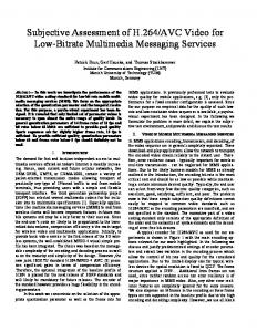
The proposed video coding system, as shown in Fig. 1 consists primarily of a 3D analysis part with/without motion compensation, and a coding part with 3D SPIHT kernel. As we can see, the decoder has the structure symmetric to that of encoder. Frames in a GOF will be rst temporally transformed with/without motion compensation. Then, each resulting frame will again be separately transformed in the spatial domain. When motion compensated ltering is performed, the motion vectors are separately lossless-coded, and transmitted over the transmission channel with high priority. With our coding system, there is no complication of a rate allocation, nor is there a feedback loop of prediction error signal, which may slow down the e�ciency of the system. With the 3D SPIHT kernel, the preset rate will be allocated over each frame of the GOF automatically according to the distribution of actual magnitudes. However, it is possible to introduce a scheme for bit re-alignment by simply scaling one or more subbands to emphasize or deemphasize the bands so as to arti cially control the visual quality of the video. This scheme is also applicable color planes of video, since it is well known fact that chrominance components are less sensitive than the luminance component to the human observer.
2.2 3D Subband Structure Fig. 2 illustrates how a GOF is decomposed into 4 temporal frequency bands. The temporal lter here is a one-dimensional (1D) unitary lter. The temporal decomposition will be followed by 2D spatial decomposition with separable unitary lters. Up to now, this temporal decomposition is the same as in the previous work in [5]. Since it has been known that temporal high frequency does 4
GOF
Temporal
Spatial
Analysis
Analysis
....
3D SPIHT Kernel Motion Vector
Motion Estimation
CHANNEL Motion Vector Reconstructed Video
....
Spatial
Temporal Synthesis
Synthesis
3D SPIHT Kernel
Figure 1: System con guration not contain much energy, previous works [3, 5, 6, 7] apply 1 level spatial decomposition. However, we found that with 3D SPIHT, further dyadic decompositions in the temporal high frequency band gives advantages over the traditional way in terms of peak signal-to-noise ratio (PSNR) and visual quality. The similar idea of so-called wavelet packet decomposition [15] also reported better visual quality. In addition, there has been some research on optimum wavelet packet image decomposition to optimize jointly the transform or decomposition tree and the quantization [17, 18]. The total number of samples in the GOF remains the same at each step in temporal or spatial analysis through the critical subsampling process. An important issue associated with 3D SBC is the choice of lters. Di�erent lters in general show quite di�erent signal characteristics in the transform domain in terms of energy compaction, and error signal in the high frequency bands [19]. The recent introduction of wavelet theory o�ers promise for designing better lters for image/video coding. However, the investigation of optimum lter design is beyond of the scope of this paper. GOF
Temporal L
Temporal LL
Temporal LLL
Temporal H
Temporal LH
Temporal LLH
Figure 2: Hierarchical GOF structure in 3D subband 5
Fig. 3 shows two templates, the lowest temporal subband, and the highest temporal subband, of typical 3D wavelet transformed frames with the \foreman" sequence of QCIF format (176 � 144). We chose 2 levels of decomposition in the spatial domain just for illustration of the di�erent 3D subband spatial characteristics in the temporal high frequency band. Hence, the lowest spatial band of each frame has dimension of 44 � 36. Each spatial band of the frames is appropriately scaled before it is displayed. Although most of the energy is concentrated in the temporal low frequency, there exists much spatial residual redundancy in the high temporal frequency band due to the object or camera motion. This is the main motivation of further spatial decomposition even in the temporal high subband. Besides, we can obviously observe not only spatial similarity inside each frame across the different scale, but also temporal similarity between two frames, which will be e�ciently exploited by the 3D SPIHT algorithm. When there is fast motion or a scene change, temporal linkages of pixels through trees does not gives any advantage in predicting insigni cance (with respect to a given magnitude threshold). However, linkages in trees contained within a frame will still be e�ective for prediction of insigni cance spatially.
Figure 3: Typical the lowest and the highest temporal subband frames with 2 levels of dyadic spatial decomposition
3 SPIHT Since the proposed video coder is based on the SPIHT image coding algorithm [16], the basic principles of SPIHT will be described brie y in this section. SPIHT algorithm utilizes three basic concepts: (1) code/transmit important information rst based on the bit-plane representation of pixels (2) ordered re nement bit-plane transmission, and (3) coding is performed along the prede ned path/trees called spatial orientation trees, which e�ciently exploit the properties of a 2D wavelet transformed image. 6
SPIHT consists of two main stages, sorting and re nement. In the sorting stage, SPIHT sorts pixels by magnitude with respect to a threshold, which is a power of two, called the level of signi cance. However, this sorting is a partial ordering, as there is no prescribed ordering among the coe�cients with the same level of signi cance or highest signi cant bit. The sorting is based on the signi cance test of pixels along the spatial orientation trees rooted from the highest level of the pyramid in the 2D wavelet transformed image. Spatial orientation trees were introduced to test signi cance of groups of pixels for e�cient compression by exploiting self-similarity and magnitude localization properties in a 2D wavelet transformed image. In other words, the SPIHT exploits the circumstance that if a pixel in the higher level of pyramid is insigni cant, it is very likely that its descendants are insigni cant. Fig. 4 depicts parent-o�spring relationship in the spatial orientation trees. In the spatial orientation trees, each node consists of 2 � 2 adjacent pixels, and each pixel in the node has 4 o�spring except at the highest level of pyramid, where one pixel in a node indicated by `*' in this gure does not have any o�spring. For practical implementation, *
Figure 4: spatial orientation tree SPIHT maintains three linked lists, the list of insigni cant pixels (LIP), the list of signi cant pixels (LSP), the list of insigni cant sets (LIS). At the initialization stage, SPIHT initializes the LIP with all the pixels in the highest levels of the pyramid, the LIS with all the pixels in the highest level of pyramid except the pixels which do not have descendants, and the LSP as an empty list. The basic function of actual sorting algorithm is to recursively partition sets in the LIS to locate individually signi cant pixels, insigni cant pixels, and smaller insigni cant sets and move their co-ordinates to the appropriate lists, the LSP, LIP and LIS, respectively. After each sorting stage, SPIHT outputs re nement bits at the current level of bit signi cance of those pixels which had been moved to the LSP at higher thresholds. In this way, the magnitudes of signi cant pixels are re ned with the bits that decrease the error the most. This process continues by decreasing the current threshold successively by factors of two until the desired bit-rate or image quality is reached. One can refer to [16] for more details. 7
4 3D SPIHT and Some Attributes This section introduces the extension of the concept of SPIHT still image coding to 3D video coding. Our main concern is to keep the same simplicity of the 2D SPIHT, still giving high performance, full embeddedness, and precise rate control.
4.1 Spatio-temporal Orientation Trees Here, we provide the 3D SPIHT scheme extended from the 2D SPIHT, having the following three similar characteristics: (1) partial ordering by magnitude of the 3D wavelet transformed video with a 3D set partitioning algorithm, (2) ordered bit plane transmission of re nement bits, and (3) exploitation of self-similarity across spatio-temporal orientation trees. In this way, the compressed bit stream will be completely embedded, so that a single le for a video sequence can provide progressive video quality, that is, the algorithm can be stopped at any compressed le size or let run until nearly lossless reconstruction is obtained, which is desirable in many applications including HDTV. In the previous section, we have studied the basic concepts of 2D SPIHT. We have seen that there is no constraint to dimensionality in the algorithm itself. Once pixels have been sorted, there is no concept of dimensionality. If all pixels are lined up in magnitude decreasing order, then what matters is how to transmit signi cance information with respect to a given threshold. In 3D SPIHT, sorting of pixels proceeds just as it would with 2D SPIHT, the only di�erence being 3D rather than 2D tree sets. Once the sorting is done, the re nement stage of 3D SPIHT will be exactly the same. A natural question arises as to how to sort the pixels of a three dimensional video sequence. Recall that for an e�cient sorting algorithm, 2D SPIHT utilizes a 2D subband/wavelet transform to compact most of the energy to a certain small number of pixels, and generates a large number of pixels with small or even zero value. Extending this idea, one can easily consider a 3D wavelet transform operating on a 3D video sequence, which will naturally lead to a 3D video coding scheme. On the 3D subband structure, we de ne a new 3D spatio-temporal orientation tree, and its parent-o�spring relationships. For ease of explanation, let us review 2D SPIHT rst. In 2D SPIHT, a node consists of 4 adjacent pixels as shown in Fig. 4, and a tree is de ned such a way that each node has either no o�spring (the leaves) or four o�spring, which always form a group of 2 � 2 adjacent pixels. Pixels in the highest levels of the pyramid are tree roots and 2 � 2 adjacent pixels are also grouped into a root node, one of them (indicated by the star mark in Fig. 4) having no descendants. A straightforward idea to form a node in 3D SPIHT is to block 8 adjacent pixels with two extending to each of the three dimension, hence forming a node of 2 � 2 � 2 pixels. This grouping is particularly useful at the coding stage, since we can utilize correlation among pixels in the same 8
node. With this basic unit, our goal is to set up trees that cover all the pixels in the 3D spatiotemporal domain. To cover all the pixels using trees, we have to impose two constraints except at a node (root node) of the highest level of the pyramid as follows. 1. Each pixel has 8 o�spring pixels. 2. Each pixel has only one parent pixel. With the above constraints, there exists only one reasonable parent-o�spring linkage in the 3D SPIHT. Suppose that we have video dimensions of M � N � F , where M , N , and F are horizontal, vertical, and temporal dimensions of the coding unit or group of frames (GOF). Suppose further that we have l recursive decompositions in both spatial and temporal domains. Thus, we have a root video dimensions of MR � NR � FR , where MR = M=2l , NR = N=2l , and FR = F=2l . Then, we de ne three di�erent sets as follows. De nition 1 A node represented by a pixel (i; j; k) is said to be a root node, a middle node, or a
leaf node according to the following rule. If i < MR and j < NR and k < FR then (i; j; k) 2 R Else if i � M=2 and j � N=2 and k � F=2, then (i; j; k) 2 L Else (i; j; k) 2 M . And, the sets R, M , and L represent Root, Middle, and Leaf respectively.
With the above three di�erent classes of a node, there exist three di�erent parent-o�spring rules. Let us denote O(i; j; k) as a set of o�spring pixels of a parent pixel (i; j; k). Then, we have the following three di�erent parent-o�spring relationships depending on a pixel location in the hierarchical tree. If (i; j; k) 2 R; O(i; j; k) = f (i ? 1 + MR ; j ? 1 + NR; k ? 1 + FR ); (i + MR ; j ? 1 + NR ; k ? 1 + FR ); (i ? 1 + MR ; j + NR ; k ? 1 + FR ); (i + MR ; j + NR; k ? 1 + FR ); (i ? 1 + MR ; j ? 1 + NR; k + FR ); (i + MR ; j ? 1 + NR; k + FR ); (i ? 1 + MR ; j + NR ; k + FR ); (i + MR; j + NR; k + FR )
g If (i; j; k) 2 M; O(i; j; k) = f (2i; 2j; 2k); (2i + 1; 2j; 2k); (2i; 2j + 1; 2k); (2i + 1; 2j + 1; 2k); (2i; 2j; 2k + 1); (2i + 1; 2j; 2k + 1); (2i; 2j + 1; 2k + 1); (2i + 1; 2j + 1; 2k + 1) g If (i; j; k) 2 L; O(i; j; k) = f�g 9
(1)
One exception as in 2D SPIHT is that one pixel in a root node has no o�spring. Fig. 5 depicts the parent-o�spring relationships in the highest level of the pyramid, assuming the root dimension is 4 � 4 � 2 for simplicity. S-LL, S-LH, S-HL, and S-HH represent spatial low-low, low-high, high-low, high-high frequency subbands in the vertical and horizontal directions. There is a group (node) of 8 pixels indicated by '*', 'a', 'b', 'c', 'd', 'e', 'f' in S-LL, where pixel 'f' is hidden under pixel 'b'. Every pixel located at '*' position in a root node has no o�spring. Each arrow originating from a root pixel pointing to a 2 � 2 � 2 node shows the parent-o�spring linkage. In Fig. 5, o�spring node 'F' of pixel 'f' is hidden under node 'B' which is o�spring node of 'b'. Having de ned a tree, the same sorting algorithm can be now applied to the video sequence along the new spatio-temporal trees, i.e., set partitioning is now performed in the 3D domain. From Fig. 5, one can see that the y
S-LH
S-HH B
C The highest level of
S-HL
pyramid (root image) b
x
G
c
S-LL
A
a
d
D
*
g
e
E
t
Figure 5: spatio-temporal orientation tree trees grow to the order of 8 branches, while 2D SPIHT has trees of order of 4. Hence, the bulk of compression can possibly be obtained by a single bit which represents insigni cance of a certain spatio-temporal tree. Since we have already 3D wavelet-transformed the video sequence to set up 3D spatio-temporal trees, the only remaining process is to compress them into a bit-stream. Essentially, it can be done by feeding the 3D data structure to the 3D SPIHT kernel. Then, 3D SPIHT will sort the data according to the magnitude along the spatio-temporal orientation trees (sorting pass), and re ne the bit plane by adding necessary bits (re nement pass). At the destination, the decoder will follow the same path to recover the data.
10
4.2 Color Video Coding So far, we have considered only one color plane, namely luminance. In this section, we will consider a simple application of the 3D SPIHT to any color video coding, while still retaining full embeddedness, and precise rate control. A simple application of the SPIHT to color video would be to code each color plane separately as does a conventional color video coder. Then, the generated bit-stream of each plane would be serially concatenated. However, this simple method would require allocation of bits among color components, losing precise rate control, and would fail to meet the requirement of the full embeddedness of the video codec since the decoder needs to wait until the full bit-stream arrives to reconstruct and display. Instead, one can treat all color planes as one unit at the coding stage, and generate one mixed bit-stream so that we can stop at any point of the bit-stream and reconstruct the color video of the best quality at the given bit-rate. In addition, we want the algorithm to automatically allocate bits optimally among the color planes. By doing so, we will still keep the claimed full embeddedness and precise rate control of 3D SPIHT. The bit-streams generated by both methods are depicted in the Fig. 6, where the rst one shows a conventional color bit-stream, while the second shows how the color embedded bit-stream is generated, from which it is clear that we can stop at any point of the bit-stream, and can still reconstruct a color video at that bit-rate as opposed to the rst case. Bit-stream of separate color coding YYYYYYYYYYYYYYYYYYYYYYYY UUUUUUUUUUUUUUVVVVVVVVVVVVV
1 color component (Y) only available at this point Embedded color bit-stream YYYYYYYYYYYYYYYYYYYYYYYYYYYYYYYYYYYYYYYYYYYYYYYYYYYYY UUUUUUUUUUUUUUUUUUUUUUUUUUUUUUUUUUUUUUUUUUUUUUUUUUUUU VVVVVVVVVVVVVVVVVVVVVVVVVVVVVVVVVVVVVVVVVVVVVVVVVVVVV
Y, U, and V all available at this point
Figure 6: Bit-streams of two di�erent methods: separate color coding (exact order of Y, U, and V) and embedded color coding (Y, U, or V selected at any point) Let us consider a tri-stimulus color space with luminance Y plane such as YUV, YCrCb, etc. for simplicity. Each such color plane will be separately wavelet transformed, having its own pyramid structure. Now, to code all color planes together, the 3D SPIHT algorithm will initialize the LIP and LIS with the appropriate coordinates of the top level in all three planes. Fig. 7 shows the initial internal structure of the LIP and LIS , where Y ,U , and V stand for the coordinates of each root pixel in each color plane. Since each color plane has its own spatial orientation trees, which are mutually exclusive and exhaustive among the color planes, it automatically assigns the bits among the planes according to the signi cance of the magnitudes of their own coordinates. The e�ect of the order in which the root pixels of each color plane are initialized will be negligible except when 11
coding at extremely low bit-rate. YYYYYYYYYYYYYYYYYYYYUUUUUVVVVV
Figure 7: Initial internal structure of LIP and LIS , assuming the U and V planes are one-fourth the size of the Y plane.
4.3 Scalability of SPIHT image/video Coder 4.3.1 Overview
In this section, we address multiresolution encoding and decoding in the 3D SPHIT video coder. Although the proposed video coder o�ers scalability in rate, it is highly desirable to have temporal and/or spatial scalabilities for today's many multi-media applications such as video database browsing and multicast network distributions. Multiresolution decoding allows us to decode video sequences at di�erent rate and spatial/temporal resolutions from one bit-stream. Furthermore, a layered bit-stream can be generated with multiresolution encoding, from which the higher resolution layers can be used to increase the spatial/temporal resolution of the video sequence obtained from the low resolution layer. In other words, we achieve full scalability in rate and partial scalability in space and time with multiresolution encoding and decoding. Since the 3D SPIHT video coder is based on the multiresolution wavelet decomposition, it is relatively easy to add multiresolutional encoding and decoding as functionalities in partial spatial/temporal scalability. In the following subsections, We rst concentrate on the simpler case of multiresolutional decoding, in which an encoded bit-stream is assumed to be available at the decoder. This approach is quite attractive since we do not need to change the encoder structure, and the decoder will work independently of the encoder. The idea of multiresolutional decoding is very simple: we partition the embedded bit-stream into portions according to their corresponding spatio-temporal frequency locations, and only decode the ones that contribute to the resolution we want. We then turn to multiresolutional encoding, where we describe the idea of generating a layered bit-stream by modifying the encoder. Depending on bandwidth availability, di�erent combinations of the layers can be transmitted to the decoder to reconstruct video sequences with di�erent spatial/temporal resolutions. Since the 3D SPIHT video coder is symmetric, the decoder as well as the encoder knows exactly which information bits contribute to which temporal/spatial locations. This makes multiresolutional encoding possible as we can order the original bit-stream into layers, with each layer corresponding to a di�erent resolution (or portion). Although the layered bit-stream is not fully embedded, the rst layer is still rate scalable. 12
4.3.2 Multiresolutional Decoding
As we have seen previously, the 3D SPIHT algorithm uses signi cance map coding and spatial orientation trees to e�ciently predict the insigni cance of descendant pixels with respect to a current threshold. It re nes each wavelet coe�cient successively by adding residual bits in the re nement stage. The algorithm stops when the size of the encoded bit-stream reaches the exact target bit-rate. The nal bit-stream consists of signi cance test bits, sign bits, and re nement bits. In order to achieve multiresolution decoding, we have to partition the received bit-stream into portions according to their corresponding temporal/spatial location. This is done by putting two
ags (one spatial and one temporal) in the bit-stream during the process of decoding , when we scan through the bit-stream and mark the portion that corresponds to the temporal/spatial locations de ned by the input resolution parameters. As the received bit-stream from the decoder is embedded, this partitioning process can terminate at any point of the bit-stream that is speci ed by the decoding bit-rate. Fig. 8 shows such a bit-stream partitioning. The dark-gray portion of the bit-stream contributes to low-resolution video sequence, while the light-gray portion corresponds to coe�cients in the high resolution. We only decode the gray portion of the bit-stream for a low-resolution sequence and scale down the 3D wavelet coe�cients appropriately before the inverse 3D wavelet transformation. We can further partition the dark-gray portion of the bit-stream in Fig. 8 for decoding in even lower resolutions. 0 1 1010 11 00 000 00 00 111111 0 1 00 111 11 000 11 111 0011 11 00000000 11 0 1 1010 11 00 000 00 00 111111 0 1 00 111 11 000 11 111 0011 11 00000000 11 Stopping point specified by the deocder
Figure 8: Partitioning of the SPIHT encoded bit-stream into portions according to their corresponding temporal/spatial locations By varying the temporal and spatial ags in decoding, we can obtain di�erent combinations of spatial/temporal resolutions in the encoder. For example, if we encode a QCIF sequence at 24 f/s using a 3-level spatial-temporal decomposition, we can have in the decoder three possible spatial resolutions (176 � 144, 88 � 72, 44 � 36), three possible temporal resolutions (24, 12, 6), and any bit rate that is upper-bounded by the encoding bit-rate. Any combination of the three sets of parameters is an admissible decoding format. Obvious advantages of scalable video decoding are savings in memory and decoding time. In addition, as illustrated in Fig. 8, information bits corresponding to a speci c spatial/temporal resolution are not distributed uniformly over the compressed bit-stream in general. Most of the lower resolution information is crowded at the beginning part of the bit-stream, and after a certain point, most of the bit rate is spent in coding the highest frequency bands which contain the detail of video which are not usually visible at reduced spatial/temporal resolution. What this means is 13
that we can set a very small bit-rate for even faster decoding and browsing applications, saving decoding time and channel bandwidth with negligible degradation in the decoded video sequence.
4.4 Multiresolutional Encoding The aim of multiresolutional encoding is to generate a layered bit-stream. But, information bits corresponding to di�erent resolutions in the original bit-stream are interleaved. Fortunately, the SPIHT algorithm allows us to keep track of the temporal/spatial resolutions associated with these information bits. Thus, we can change the original encoder so that the new encoded bit-stream is layered in temporal/spatial resolutions. Speci cally, multiresolutional encoding amounts to putting into the rst (low resolution) layer all the bits needed to decode a low resolution video sequence, in the second (higher resolution) layer those to be added to the rst layer for decoding a higher resolution video sequence and so on. This process is illustrated in Fig. 9 for the two-layer case, where scattered segments of the dark-gray (and light-gray) portion in the original bit-stream are put together in the rst (and second) layer of the new bit-stream. A low resolution video sequence can be decoded from the rst layer (dark-gray portion) alone, and a full resolution video sequence from both the rst and the second layers. 1 0 0 1 0 1 0 1
0110 1010
11 00 000 00 00 11111 00 111 11 000 11 111 0011 11 0000000 11 00 11 000 00 00 00 111 11 000 11 111 0011 11 00 11 1010101011 00 000 00 00 11111 00111 11 00011 111 0011 11 0000000 11 1010101011 00 000 00 00 00111 11 00011 111 0011 11 00 11
Original bit-stream
Layered bit-stream
111 000 00 11 000000000 111111111 000000000 111111111 000000000 111111111 000000000 111111111
111 000
Figure 9: A multiresolutional encoder generates a layered bit-stream, from which the higher resolution layers can be use to increase the spatial resolution of the video obtained from the low resolution layer. As the layered bit-stream is a reordered version of the original one, we lose overall scalability in rate after multiresolutional encoding. But the rst layer (i.e., the dark gray layer in Fig. 9) is still embedded, and it can be used for lower resolution decoding. Unlike multiresolutional decoding in which the full resolution encoded bit-stream has to be 14
transmitted and stored in the decoder, multiresolutional encoding has the advantage of wasting no bits in transmission and decoding at lower resolution. The disadvantages are that it requires both the encoder and the decoder agree on the resolution parameters and the loss of embeddedness at higher resolution, as mentioned previously.
5 Motion Compensation When there is a considerable amount of motion either in the form of global camera motion or object motion within a GOF, the PSNR of reconstructed video will uctuate noticeably due to pixels with high magnitude in the temporal high frequency. On the contrary, if there were a way in which we can measure motion so accurately that we can remove a signi cant amount of temporal redundancy, there will be not many signi cant pixels in the temporal high frequency subbands, leading to good compression scheme. Fortunately, as we earlier discussed, typical applications with very low bit-rate deal with rather simple video sequences with slow object and camera motion. Even so, to remove more temporal redundancy and PSNR uctuation, we attempt to incorporate a motion compensation (MC) scheme as an option. In this section, we digress from the main subject of our proposed video coder, and review some of the previous works on motion compensation. Block matching is the most simple in concept, and has been widely used for many practical video applications due to its smaller hardware complexity. In fact, today's video coding standards such as H.261, H.263, and MPEG 1-2 are all adopting this scheme for simplicity. Hence, we start with a brief introduction of the block matching algorithm, and its variations, followed by some representative motion compensated ltering schemes.
5.1 Block Matching Method As with other block-based motion estimation methods, the block matching method is based on three simple assumptions: (1) the image is composed of moving blocks, (2) there only exists translational motion, and (3) within a certain block, the motion vector is uniform. Thus, it fails to track more complex motions such as zooming, and rotation of the object, and motion vectors obtained thereby are not accurate enough to describe true object motion. In the block matching method, the frame being encoded is divided into blocks of size M � N . For each block, we search for a block in the previous frame within a certain search window which gives the smallest measure of closeness (or minimum distortion measure). The motion vector is taken to be the displacement vector between these blocks. Suppose that we have a distortion measure function D(�), which is a function of the displacement dx and dy between the block in the current frame and a block in the previous frame. Then, mathematically, the problem can be formulated as ^ dy ^ ) = arg min D(dx; dy ) (dx; dx;dy)
(
15
(2)
There are several possible measurement criteria including maximum cross-correlation, minimum mean squared error (MSE), minimum mean absolute error (MAD), and maximum matching pel count (MPC). We formally provide the two most popular criteria (MSE, and MAD) just for completeness. 1 MSE (dx; dy) = MN [I (x; y; t) ? I (x ? dx; y ? dy; t ? 1)]2 (3)
X
x;y)2S
(
and
1 MAD(dx; dy) = MN
X
x;y)2S
j I (x; y; t) ? I (x ? dx; y ? dy; t ? 1) j;
(4)
(
where I (x; y; t) denotes the intensity at co-ordinates (x; y; t) and S denotes the block of size M � N . The advantage of the full search block matching method above is that it guarantees an optimum solution within the search region in terms of the given distortion measure. However, it requires a large number of computations. Suppose that we have M = N = 8. Then, it requires 64 di�erences, and then computation of the sum of the absolute mean square values of each di�erence. If we have ^ , dy ^ ), then we need more than 950 comparisons. search region of +15 to ?15 for (dx There are several ways to reduce computational complexity. One way is to use larger size of block. By doing so, we have a fewer number of blocks in the frame (thus, we have smaller amount of motion vectors), while the number of computations per comparison will increase. The drawback with large block size is that it becomes more likely to contain more than one object moving in di�erent directions. Hence, it is more di�cult to estimate local object motion. Another way is to reduce the search range, which will reduce number of comparisons for best match search within the search range. However, it will increase the probability of missing a true motion vector. Meanwhile, there are several fast search algorithms such as three-step search, and cross-search. Instead of searching for every possible candidate motion vector, those algorithms evaluate the criterion function only at a predetermined subset of the candidate motion vector locations. Hence, again there is trade-o� between speed and performance. For more details of search strategies, one can refer to [20]. Choice of optimum block size is of importance for any block-based motion estimation. As mentioned above, too large a block size fails to meet the basic assumptions in that within a block actual motion vectors may vary. If a block size is too small, a match between the blocks containing two similar gray-level patterns can be established. Because of these two con icting requirements, the motion vector eld is usually not smooth [21]. Hierarchical block matching algorithm, discussed in the next section, has been proposed to overcome these problems, and our proposed video codec employs this method for motion estimation.
16
5.2 Hierarchical Motion Estimation Hierarchical representations of image in the form of wavelet transform has been proposed for improved motion estimation. The basic idea of the hierarchical motion estimation is to perform motion estimation at each level successively. The motion vectors estimated at the highest level of pyramid are used for the initial estimates of the motion vectors at the next state of the pyramid to produce motion vector estimates more accurately. At higher resolution levels, we are allowed to use a small search range since we start with a good initial motion vector estimate. Fig. 10 illustrates the procedure of how a motion vector gets re ned at each stage. In general, a more accurate and refining
refining
Figure 10: Hierarchical motion estimation smoother motion vector eld (MVF) can be obtained with this method, which results in a lower amount of side information for motion vector coding. Moreover, since the computational burden with full search block matching method is now replaced by a hierarchical wavelet transform plus full search block matching with much smaller search window, we can have faster motion estimation. The additional computational complexity for the wavelet transform is usually much smaller than that of full search block matching with a relatively large search window.
5.3 Motion Compensated Filtering Motion compensated temporal analysis has been considered to take better advantage of temporal correlation. The basic idea is to perform temporal ltering along the motion trajectory. Although it is conceptually simple and reasonable, it was considered to to be di�cult to translate into practice or even impractical [22] due to the complexity of motion in video and the number of connected/unconnected pixels inevitably generated. However, recently there have been some promising results in this area [5, 6, 21], where a heuristic approach has been made to deal with the connected/unconnected pixel problem. Fig. 11 illustrates the problem, and shows solutions to have perfect reconstruction in the presence of unconnected or doubly connected pixels. With Ohm's method [6], for any remaining unconnected pixels, the original pixel value of the current frame is 17
a - pixels in the previous frame b - pixels in the current frame
Unconnected pixel Connected pixel
(b-a)/2
(b-a)/2
(a+b)/2
(b-a)/2 (b-a)/2
a a
(a+b)/2 (a+b)/2 b
(b-a)/2
(b-a)/2
(a+b)/2 b
Previous frame
Current frame
(b-a)/2
High Low Ohm’s method
(b-a)/2 Low High Choi’s method
Figure 11: MC ltering method in the presence of connected/unconnected pixels Level 3 2 1 Search Window �2 �2 �2 Option 1 4 8 16 Option 2 8 16 32 Table 1: Set of parameters for 3-Level hierarchical block matching inserted into the temporal low-subband, and the scaled displace frame di�erence (DFD) into the temporal high-subband. With Choi's method [21], for an unconnected pixel in the reference frame, its original value is inserted into the temporal low-subband with the assumption that unconnected pixels are more likely to be uncovered ones, and for an unconnected one in the current frame, a scaled DFD is taken. In this proposal, we adopted the method in [21] for MC temporal ltering. One of the main problems in incorporating motion compensation into video coding, especially at very low bit-rate, is the overhead associated with the motion vector. A smaller block size generally increase the amount of overhead information. Too large a block size fails to reasonably estimate diverse motions in the frames. In [21], several di�erent block sizes were used with a hierarchical, variable size block matching method. In that case, additional overhead for the image map for variable sizes of blocks and the motion vectors are needed to be transmitted as side information. Since we can not know the characteristics of the video beforehand, it is di�cult to choose optimum block size and search window size. However, empirically we provide Table 1 for the parameters for our hierarchical block matching method for motion estimation, where there are two options in choosing block size. Motion vectors obtained at a certain level will be scaled up by 2 to be used for initial motion vectors at the next stage.
18
option temporal spatial motion 1 lter 1 lter 1 no 2 lter 2 lter 1 yes Table 2: Filter choices for 3D Decomposition of video
6 Implementation Details Performance of video coding systems with the same basic algorithm can be quite di�erent according to the actual implementation. Thus, it is necessary to specify the main features of the implementation in detail. In this section, we will describe some issues such as lter choice, image extension, and modeling of arithmetic coding, that are important in practical implementation. Although there are many di�erent kinds of lters, we chose separable 1D lters. Speci cally, we have two di�erent kind of lters: 9/7 bi-orthogonal Daubechies lter ( lter 1) [23], and 2 tap Haar lter ( lter 2) [21, 3] for practical implementation. Each has its own advantage for a certain type of design option. Filter 1 has the better energy compaction of the two, and usually outperforms the other in terms of PSNR. Filter 2 is simple, does not require image extension at the boundary of image/video, and can be easily incorporated into a motion compensation scheme. Either the same lter can be used or two di�erent lters can be used for temporal, and spatial domain. For our simulation, we have two di�erent options for 3D decomposition, as shown in Table 2. With these lters, ltering is performed with a convolution operation recursively. Since we need to preserve an even number for dimensions of the highest level of pyramid image of each frame, given some desired number of spatial levels, it is often necessary extend the frame to a larger image before 2D spatial transformation. For example, we want to have at least 3 levels of spatial ltering for QCIF (176 � 144) video sequence with 4:2:0 or 4:1:1 subsampled format. For the luminance component, the highest level of the image is 22 � 18. However, for chrominance components, it will be 11 � 9 which is not appropriate for the coding stage. To allow 3 levels of decomposition, a simple extrapolation scheme is used to make dimension of chrominance component 96 � 80 which results in 12 � 10 of root image after 3 levels of decomposition. Generally, extending the image by arti cially augmenting its boundary can cause some loss of performance. However, extending the image in a smooth fashion (since we do not want to generate arti cial high frequency coe�cients), the performance loss is expected to be minimal. After the 3D subband/wavelet transformation is completed, the 3D SPIHT algorithm is applied to the resulting multiresolution pyramid. Then, the output bit-stream is further compressed with an arithmetic encoder [24]. To increase the coding e�ciency, groups of 2 � 2 � 2 coordinates were kept together in the list. Since the amount of information to be coded depends on the number of insigni cant pixels m in that group, we use several di�erent adaptive models, each with 2m symbols, where m 2 f1; 2; 3; 4; 5; 6; 7; 8g, to code the information in a group of 8 pixels. By using 19
di�erent models for the di�erent number of insigni cant pixels, each adaptive model contains better estimates of the probabilities conditioned to the fact that a certain number of adjacent pixels are signi cant or insigni cant. Lastly, when motion compensated temporal ltering is applied, we will need to code motion vectors. When GOF = 16, we have 8 rst level MVFs, 4 second level MVFs, and 2 third level MVF, resulting in total 14 MVFs to code. In the experiment, we have found that MVFs from di�erent levels have quite di�erent statistical characteristics. In general, more unconnected pixels are generated at higher levels of temporal decomposition. Furthermore, horizontal and vertical motion are assumed to be independent of each other. Thus, each motion vector component is separately coded conditioned to the level of decomposition. For the chrominance components, the motion vector obtained from the luminance component will be used with an appropriate scale factor.
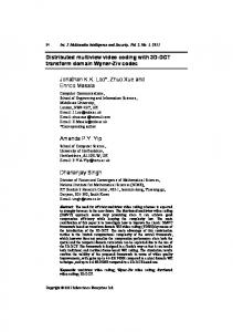
7 Simulation and Performance Analysis In this section, we provide simulation results and compare the proposed video codec with H.263 in various aspects such as objective and subjective performance, system complexity, and performance at di�erent camera and object motion. The latest test model number of H.263, tmn2.0 (test model number 2.0), was downloaded from the public domain (ftp://bonde.nta.no/pub/tmn/). As is tmn2.0, the 3D SPIHT video codec is a fully implemented software video codec. We tested three di�erent video sequences: \Carphone", \Mother and Daughter", and \Hall Monitor". These video sequences cover a variety of object and camera motions. \Carphone" is a representative sequence for video-telephone application. This has more complicated object motion than the other two, and camera is assumed to be stationary. However, the background outside the car window changes very rapidly. \Mother and Daughter" is a typical head-and-shoulder sequence with relatively small object motion and camera is also stationary. The last sequence \Hall Monitor" is suitable for a monitoring application. The background is always xed and some objects (persons) appear and then disappear. All the tests were performed at the frame-rate of 10 fps by coding every third frame. For a parallel comparison, we rst run with H.263 at a target bit-rates (30k and 60k) with all the advanced options (-D -F -E) on. In general, H.263 does not give the exact bit-rate and frame-rate due to the bu�er control. For example, tmn produced actual bit-rate and frame-rate of 30080 bps and 9.17 fps for the target bit-rate and frame-rate of 30000 bps and 10 fps. With our proposed video codec, the exact target bit rates can be obtained. However, since 3D SPIHT is fully embedded video codec, we only needed to decode at the target bit-rates with one bit-stream compressed at the larger bit-rate. Figs. 12, 13, and 14 show frame-by-frame PSNR comparison among MC 3D SPIHT, 3D SPIHT, 20
and H.263. We chose GOF = 16 for the simulation. From the gures, 3D SPIHT is 0.89 { 1.39 dB worse than H.263 at the bit-rate of 30k. At the bit-rate of 60k, less PSNR advantage of H.263 over 3D SPIHT can be observed except the \Hall Monitor" sequence for which 3D SPIHT has a small advantage over H.263. Comparing of MC 3D SPIHT with 3D SPIHT, in general MC 3D SPIHT gives more stable PSNR uctuation than 3D SPIHT without MC, since MC reduces large magnitude pixels in temporal high subbands resulting in more uniform rate allocations over the GOF . In addition, a small advantage of MC 3D SPIHT over 3D SPIHT was obtained for the sequences with translational object motion. However, for \Hall Monitor" sequence, where 3D SPIHT outperforms MC 3D SPIHT in terms of average PSNR, side information associated with motion vectors seemed to exceed the gain provided by motion compensation. In terms of visual quality, H.263, 3D SPIHT, and MC 3D SPIHT showed very competitive performance as shown in Figs. 15, 16, and 17 although our proposed video coders have lower PSNR values at the bit rate of 30 kbps. In general, H.263 preserves edge information of objects better than 3D SPIHT, while 3D SPIHT exhibits blurs in some local regions. However, as we can observe in Fig. 15, H.263 su�ers from blocking artifacts around the mouth of the person and background outside the car window. In overall, 3D SPIHT and MC 3D SPIHT showed comparable results in terms of average PSNR and visual quality of reconstructed frames. As in the most 3D subband video coders, one can observe that PSNR dips at the GOF boundaries partly due to the object motion and partly due to the boundary extension for the temporal ltering. However, they are not visible in the reconstructed video. Smaller number of GOF such as 4 and 8 has been used with shorter lters such as Haar and S+P [25] lters for temporal ltering. Results are not signi cantly di�erent, but slightly inferior in terms of average PSNR. However, more uniform frame-by-frame PSNR uctuation were observed. Next, computational complexity of 3D SPIHT and MC 3D SPIHT are accessed in terms of total execution time for both encoder and decoder and compared with that of H.263 on SUN SPARC 20 machine in encoding/decoding \Carphone" sequence from 0 - 285 at 10 fps, and 30 kbps. 9/7 bi-orthogonal Daubechies lter with 3D SPIHT and 2 tap Haar lter with MC 3D SPIHT were used for temporal ltering. For spatial ltering, both 3D SPIHT and MC 3D SPIHT use 9/7 biorthogonal Daubechies lter. From Table 3, 3D SPIHT requires less than half the complexity of H.263, while MC 3D SPIHT requires about 1.2 times higher complexity than H.263. In MC 3D SPIHT, most of the execution time is spent in hierarchical motion estimation. Considering that the 3D SPIHT video coder is not fully optimized and that there has been active research on fast lter design, 3D SPIHT shows a promise of software-only video coder as can be seen from actual coding and decoding times in the Table 4. As we discussed earlier section, scalability in video coding is very important for many multimedia applications. Fig. 18 shows rst frames of the decoded \Carphone" sequence at di�erent 21
3D SPIHT MC 3D SPIHT H.263 Relative complexity 1 3.09 2.53 Table 3: Comparison of 3D SPIHT, MC 3D SPIHT, and H.263 relative computational complexity for encoding 0 - 285 \Carphone" sequence at 10 fps, and 30 kbps. Complexity is computed on SUN SPARC 20 machine. Functions time in sec relative time (%) 3D wavelet transform 16.22 56.95 3D SPIHT compression 1.27 4.46 Maximum magnitude computation 6.16 21.63 I/O 4.83 16.96 Total time 28.48 100.00 Functions time in sec relative time (%) 3D inverse-wavelet transform 14.60 78.37 3D SPIHT decompression 0.86 4.62 I/O 3.17 17.01 Total time 18.63 100.00 Table 4: System complexity of 3D SPIHT encoder/decoder in terms of time. Coding time is based on Sun SPARC 20. The video \Carphone" (0 - 285) was coded at 10 fps, and 30 kbps. Total time is for encoding/decoding 96 frames spatial/temporal resolutions from the same encoded bit-stream. In order to quantitatively access the time saving in decoding multiresolutional image and video sequence, we give the total decoder running time including inverse wavelet transform, and I/O in Table 5 on a SUN SPARC 20. From Table 5, we observe that signi cant computational time saving can be obtained with the multiresolutional decoding scheme. Especially when we decoded at half spatial/temporal resolution we obtained more than 5 times faster decoding speed than full resolution decoding.
8 Conclusions In this paper, we presented an embedded wavelet-based video coder by introducing spatio-temporal orientation trees extended from 2D SPIHT for image coding for very low bit-rate video coding. The video coder is fully embedded and a variety of video quality thus can be obtained with a single compressed bit-stream. Since the algorithm approximates the original sequence successively by bit plane quantization according to magnitude comparisons, a precise rate control and self-adjusting 22
Spatial full (%) Spatial half (%) Temporal full 100 31.52 Temporal half 62.76 19.39 Table 5: Relative decoding time in % for the \Carphone" sequence at di�erent temporal and spatial resolutions. Full resolution time is 18.63 second for decoding frame 0 { 285 at 10 fps and 30 kbps. (Hence, total number of frames decoded is 96) rate allocations are achieved. In addition, spatial and temporal scalability can be easily incorporated into the system to meet various types of display parameter requirements. The proposed video coding is so e�cient that it showed comparable results visually and measurably to that of H.263 even without motion compensation. We also provided that a motion compensation scheme can be implemented to reduce large magnitude pixels in the temporal high frequency bands to achieve more uniform rate allocations over a certain size of GOF . Lastly, the intention of future research will be to design a motion compensated spatio-temporal orientation tree in which MC and and prediction trees will be jointly optimized not only to take better advantage of temporal correlation but also to better predict insigni cance of pixels in the temporal high frequency subbands.
References [1] E. Reusens, T. Ebrahimi, and M. Kunt, \Dynamic coding of visual information," IEEE Transactions on Circuit and System for Video Technology, vol. 7, no. 3, pp. 489{500, June 1997. [2] G. Karlsson and M. Vetterli, \Three dimensional subband coding of video," Proc. Int. Conf. on Acoust., Speech, and Signal Processing (ICASSP), pp. 1100{1103, April 1988. [3] C. I. Podilchuk, N. S. Jayant, and N. Farvardin, \Three-dimensional subband coding of video," IEEE Transactions on Image Processing, vol. 4, no. 2, pp. 125{139, Feb. 1995. [4] T. Kronander, \New results on 3-dimensional motion compensated subband coding," Proc. PCS-90, Mar 1990. [5] J. R. Ohm, \Advanced packet video coding based on layered VQ and SBC techniques," IEEE Transactions on Circuit and System for Video Technology, vol. 3, no. 3, pp. 208{221, June 1993. [6] J. R. Ohm, \Three-dimensional subband coding with motin compensation," IEEE Transactions on Image Processing, vol. 3, no. 5, pp. 559{571, Sep. 1994. 23
[7] S. J. Choi and J. W. Woods, \Motion-compensated 3-d subband coding of video," Submitted to IEEE Transactions on Image Processing, 1997. [8] V. M. Bove and A. B. Lippman, \Scalable open-architecture television," SMPTE J., pp. 2{5, Jan. 1992. [9] D. Taubman and A. Zakhor, \Multirate 3-d subband coding of video," IEEE Transactions on Image Processing, vol. 3, no. 5, pp. 572{588, Sep. 1994. [10] D. Taubman, Directionality and scalability im Image and Video Compression, Ph.D. thesis, University of California, Bekerley, 1994. [11] J. M. Shapiro, \An embedded wavelet hierarchical image coder," Proc. IEEE Int. Conf. on Acoust., Speech, and Signal Processing (ICASSP), San Francisco, pp. IV 657{660, March 1992. [12] A. Said and W. A. Pearlman, \Image compression using the spatial-orientation tree," Proc. IEEE Int. Symp. Circuits and Systems, pp. 279{282, May 1993. [13] Y. Chen and W. A. Pearlman, \Three-dimensional subband coding of video using the zero-tree method," Visual Communications and Image Processing '96, Proc. SPIE 2727, pp. 1302{1309, March 1996. [14] J. Luo, X. Wang, C. W. Chen, and K. J. Parker, \Volumetric medical image compression with three-dimensional wavelet transform and octave zerotree coding," Visual Communications and Image Processing'96, Proc. SPIE 2727, pp. 579{590, March 1996. [15] J. Y. Tham, S. Ranganath, and A. A. Kassim, \Highly scalable wavelet-based video codec for very low bit-rate environment," To appear in IEEE Journal on Selected Area in Communications, 1998. [16] A. Said and W. A. Pearlman, \A new fast and e�cient image codec based on set partitioning in hierarchical trees," IEEE Transactions on Circuits and Systems for Video Technology, vol. 6, pp. 243{250, June 1996. [17] Z. Xiong, K. Ramchandran, and M. T. Orchard, \Wavelet packet image coding using spacefrequency quantization," Submitted to IEEE Transactions on Image Processing, 1996. [18] Z. Xiong, K. Ramchandran, and M. T. Orchard, \Space-frequency quantization for wavelet image coding," IEEE Transactions on Image Processing, vol. 6, pp. 677{693, May 1997. [19] K. Sayood, Introduction to Data Compression, Morgan Kaufman Publisher, Inc, 1996, pp. 285{354. 24
[20] A. M. Tekalp, Digital Video Processing, Prentice Hall, Inc, 1995. [21] S. J. Choi, Three-Dimensional Subband/Wavelet Coding of Video with Motion Compensation, Ph.D. thesis, Rensslaer Polytechnic Institute, 1996. [22] T. Kronander, Some Aspects of Perception Based Image Coding, Ph.D. thesis, Linkeoping University, Linkeoping, Sweden, 1989. [23] M. Antonini, M. Barlaud, P. Mathieu, and I. Daubechies, \Image coding using wavelet transform," IEEE Transactions on Image Processing, vol. 1, pp. 205{220, 1992. [24] I. H. Witten, R. M. Neal, and J. G. Cleary, \Arithmetic coding for data compression," Communications of the ACM, vol. 30, no. 6, pp. 520{540, June 1987. [25] A. Said and W. A. Pearlman, \Reversible image compression via multiresolution representation and predictive coding," Proc. SPIE, vol. 2094, pp. 664{674, Nov. 1993.
25
Carphone sequence at 10 fps and 30000 bps 40 −− : H.263 mean = 31.42 dB 38
− −o : MC 3D SPIHT mean = 30.39 dB dash dot : 3D SPIHT mean = 30.22 dB
36
PSNR in dB
34
32
30
28
26
24
22
0
50
100
150 Frame number
200
250
300
Carphone sequence at 10 fps and 60000 bps 45 −− : H.263 mean = 34.29 dB − −o : MC 3D SPIHT mean = 33.19 dB dash dot : 3D SPIHT mean = 32.97 dB
PSNR in dB
40
35
30
25
0
50
100
150 Frame number
200
250
300
Figure 12: Frame-by-frame PSNR comparison of 3D SPIHT, MC 3D SPIHT, and H.263 at 30 and 60 kbps and 10 fps with \Carphone" sequence 26
Mother and daughter sequence at 10 fps and 30000 bps 42 −− : H.263 mean = 34.10 dB 40
− −o : MC 3D SPIHT mean = 32.78 dB dash dot : 3D SPIHT mean = 32.71 dB
38
PSNR in dB
36
34
32
30
28
26
24
0
50
100
150 Frame number
200
250
300
250
300
Mother and daughter sequence at 10 fps and 60000 bps 44 −− : H.263 mean = 36.66 dB 42
− −o : MC 3D SPIHT mean = 35.69 dB dash dot : 3D SPIHT mean = 35.57 dB
40
PSNR in dB
38
36
34
32
30
28
26
0
50
100
150 Frame number
200
Figure 13: Frame-by-frame PSNR comparison of 3D SPIHT, MC 3D SPIHT, and H.263 at 30 and 60 kbps and 10 fps with \Mother and Daughter" sequence 27
Hall Monitor sequence at 10 fps and 30000 bps 42
40 −− : H.263 mean = 33.84 dB − −o :MC 3D SPIHT mean = 32.30 dB
38
dash dot : 3D SPIHT mean = 32.95 dB
PSNR in dB
36
34
32
30
28
26
0
50
100
150 Frame number
200
250
300
250
300
Hall Monitor sequence at 10 fps and 60000 bps 44 −− : H.263 mean = 37.80 dB 42
− −o : MC 3D SPIHT mean = 37.36 dB dash dot : 3D SPIHT mean = 37.95 dB
PSNR in dB
40
38
36
34
32
0
50
100
150 Frame number
200
Figure 14: Frame-by-frame PSNR comparison of 3D SPIHT, MC 3D SPIHT, and H.263 at 30 and 60 kbps and 10 fps with \Hall Monitor" sequence 28
Figure 15: The same reconstructed frames at 30 kbps and 10 fps (a)Top-left: original \Carphone" frame 198 (b)Top-right: H.263 (c)Bottom-left: 3D SPIHT (d)Bottom-right: MC 3D SPIHT
29
Figure 16: The same reconstructed frames at 30 kbps and 10 fps (a)Top-left: original \Mother and Daughter" frame 102 (b)Top-right: H.263 (c)Bottom-left: 3D SPIHT (d)Bottom-right: MC 3D SPIHT
30
Figure 17: The same reconstructed frames at 30 kbps and 10 fps (a)Top-left: original \Hall Monitor" frame 123 (b)Top-right: H.263 (c)Bottom-left: 3D SPIHT (d)Bottom-right: MC 3D SPIHT
31
Figure 18: Multiresolutional decoded frame 0 of \Carphone" sequence with the embedded 3D SPIHT video coder (a)Top-left: spatial half resolution (88 x 72 and 10 fps) (b)Top-right: spatial and temporal half resolution (88 � 72 and 5 fps) (c)Bottom-left: temporal half resolution (176 � 144 and 5 fps) (d)Bottom-right: full resolution (176 � 144 and 10 fps)
32