Visualisation Techniques to Support Derivation Tasks in. Software Product Line Development. Daren Nestor. 1. , Luke O'Malley. 2. , Patrick Healy. 1.
Visualisation Techniques to Support Derivation Tasks in Software Product Line Development Daren Nestor1, Luke O’Malley2, Patrick Healy1, Aaron Quigley2, Steffen Thiel1 Lero – The Irish Software Engineering Research Centre 1
2
University of Limerick Limerick, Ireland
University College Dublin Dublin, Ireland
{daren.nestor | luke.omalley | patrick.healy | aaron.quigley | steffen.thiel}@lero.ie
in time-to-market, cost, productivity, and quality [1]. Industrial size product lines can easily incorporate thousands of variation points and configuration parameters for product customization [2]. Managing this amount of variability is extremely complex and requires sophisticated modelling techniques. In particular, there is a strong need for appropriate approaches that support the different stakeholders in carrying out their development tasks in software product line efforts with a large number of variants [3]. This paper elaborates on the notion of using information and software visualisation techniques to support variability management, and particularly product derivation, in industrial product lines. Visualisation has proven useful to amplify cognition in a number of ways, for example, by increasing the “memory” and “amount of processing” available to users, by supporting the search for information, and by encoding information in a manipulable medium [4]. Visualisation takes abstract data, and gives it a form suitable for visual presentation. Such data can be explicitly collected from software or can be codified by software engineers from their own implicit knowledge. With suitable techniques such visualisations can also amplify the cognition about large and complex data sets created and used in industrial software product line engineering. The exploration of the potential of visual representations such as trees and graphs combined with the effective use of human interaction techniques such as dynamic queries and direct manipulation when applied in a
Abstract Adopting a software product line approach allows companies to realise significant improvements in time-to-market, cost, productivity, and system quality. A fundamental problem in software product line engineering is the fact that a product line of industrial size can easily incorporate several thousand variation points. The scale and interdependencies can lead to variability management and product derivation tasks that are extremely complex to manage. This paper investigates visualisation techniques to support and improve the effectiveness of these tasks.
1.
Introduction
In software product line engineering similarities between products are exploited to reduce the amount of work involved in producing a new software product. As a result of dealing with products with similarities software product line engineering has rapidly emerged as an important software development paradigm during the last few years. Developing products based on a product line approach allows companies to build a variety of systems with a minimum of technical diversity and to realise significant improvements Copyright © 2007 Lero. Permission to copy is hereby granted provided the original copyright notice is reproduced in copies made.
1
software product line context are interesting and novel research aspects underlying this work. The remainder of the paper is organised as follows: Section 2 gives a brief overview of variability management and product derivation approaches. Section 3 presents a reference model that frames the visualisation research into software product lines. Section 4 identifies important product line engineering scenarios. It further discusses visualisation techniques that are useful in managing the tasks forthcoming from the scenarios. Section 5 provides a discussion on information presentation and user interaction in the context of the visualisation research related to the product line scenarios presented. Section 6 describes further research directions. Finally, Section 7 summarises the conclusions of this work.
2.
Variability Management Product Derivation
[7]). In this context, researchers have suggested the integration of product line variability into traditional development artefacts such as feature models (e.g., [8]), use case models (e.g., [6]), architecture variability models (e.g., [7]), and class variability diagrams (e.g., [9]). Other researchers have emphasized the need for separating variability information from the original development artefacts in order to help delineate concerns, to support the communication of variability and to improve consistency (e.g., [10]). Recently, the formalisation of variability emerged as an important research area, especially in support tool development and automation in software product line engineering. Overall, current variability modelling techniques are effective in bundled or delineated methods, especially for small scale system modelling and development.
and 2.2.
Variability management is the process by which the variability of the product line development artefacts (e.g., architectural models, software components, and hardware components) is planned, documented, and managed throughout the development lifecycle. Variability management supports critical product line engineering tasks such as product derivation. Variation points identify locations in product line artefacts at which variation will occur [5]. The binding time refers to the moment in a product’s lifecycle at which a particular variant for a variation point is bound to the system, e.g. pre- or post-deployment. A realisation mechanism refers to the technique that is used to implement the variation point. A variant is an artefact that has been realised (or configured) for a particular product. It can also be used to describe a derived product. In the remainder of this section we provide an overview of modelling and representation approaches that support variability management. We also briefly discuss product derivation activities.
2.1.
Variability Representations
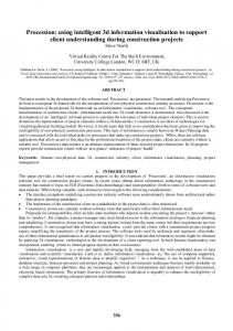
Figure 1: Feature model Common notations used in existing approaches and tools for representing variability in product lines are feature diagrams (e.g., [8]). A feature diagram is a graphical representation of a feature model that shows a hierarchically structured set of features of the product line (see Figure 1). Here features are represented as nodes and relationships between features as links (or edges). Possible relationships between features are usually categorized based on their availability within the constraints imposed by the model. The legend in Figure 1 illustrates examples of those relationships. A feature diagram is typically represented as a tree where primitive features are leaves and compound features are interior nodes.
Variability Modelling Approaches
Several models and approaches have been proposed for representing variability information in various development phases of a software product line approach, especially in requirements engineering (e.g., [6]) and architecture design (e.g.,
2
Some researchers have proposed approaches to model variability by using specialised notations (e.g., [10]). These models are often created from meta-models that define how to build valid model instances. Like feature diagrams, they often form hierarchical structures, with the nodes being in UML notation.
2.3.
stance of the asset, or they can be shared with all the members of the product line. Validation means validating the system with respect to requirements and checking the consistency and correctness of the component configuration. McGregor [12] introduces the production plan to facilitate product derivation in a product line organization. The production plan is introduced as the main communication vehicle between the domain engineers (platform developers) and application engineers (product builders). It describes the artefacts needed to build a product, how those artefacts are used, and the skills and tools needed to produce the product. The production plan is accompanied by an attached process that describes how to specialize the plan to a productspecific production plan. Deelstra et al. [11] also identified a set of problems associated with derivation. They noted that there tended to be an unmanageable number of variation points and variants, inappropriate organisation of variation points, decreased traceability of relevant information on components, repetition of development during derivation between different projects as well as other problems. The authors are convinced that visualisation could be of use in supporting solutions to these problems.
Product Derivation
Product derivation has been described as the “process of constructing a product from product line software assets” [11]. This is partially done by exploiting variability. The assets referred to can be software, hardware or mechanical components, as well as documentation, which are reused in an organised manner throughout the product line. The process of product derivation can be divided into two phases: the initial phase and the iterative phase [11]. The initial phase involves using requirements to drive the primary derivation of a product using either assembly from existing components or the selection of the closest existing configuration and adapting it to the requirements of the product being derived. In some cases, an initial configuration sufficiently implements the desired product. In most cases, however, one or more cycles through the iterative phase are required for any number of reasons, such as requirements changing, the assets having been modified, or to ensure that communication between the components is working as expected. The iterative phase involves adaptation of the selected assets, and validation of any adaptations. The adaptations can be product specific or evolutionary, that is, they can be specific to this in-
3.
Visualisation Reference Model
Visualisation can be described as “adjustable mappings from data to visual form” [4]. Figure 2 shows a visualisation reference model which illustrates these mappings for variability visualisation in the context of software product lines. This model is based on [4] and represents an extension of the model presented in [3]. In Figure 2, the
Figure 2: Reference model for variability visualisation
3
arrows indicate a series of data transformations from raw data through visual form to a human perceiver. The arrows flowing from the human perceiver at the right into the transformations themselves indicate the adjustment of these transformations by user-operated controls. The dashed arrows leading from software product line (SPL) scenarios to each of the data stages, indicates that all the tasks are informed by these scenarios. The first type of transformation is Data Transformations which map raw SPL Data (i.e., data about the software product line artefacts, their variability, and the dependencies among them) into Data Tables. Data Tables are relational descriptions of data extended to include metadata (i.e. descriptive information about the data). The usual strategy here is to achieve a set of relations that are more structured than the original data and thus easier to map to visual forms. Visual Mappings then transform Data Tables into Visual Structures. Visual Structures are structures that combine spatial substrates (e.g., nominal or ordinal axis), marks (points, lines, areas, volumes), and graphical properties (e.g., colour, texture or intensity) to encode information. It is important to note that a Visual Mapping preserves the data and that it can be perceived well by the human. View Transformations create Views of the Visual Structures by specifying graphical parameters such as position, scaling, and clipping. As such, View Transformations interactively modify and augment Visual Structures to turn static presentations into visualisations. Finally, user interaction controls parameters of these transformations, restricting the view to certain data ranges, for example, or changing the nature of the transformation. The visualisation and their controls are used in support of some product line development task (e.g., derive a lowend product for the European market). These tasks are outlined by the SPL scenarios. There are many varieties of visualisation that could be applied in a software product line context. A detailed description of all possible kinds of visualisation techniques is beyond the scope of this paper. However, for hierarchical data (which includes computer programs) various graphs have proven useful. For a comprehensive overview of various graph techniques refer to the survey of Herman et al. [13] for navigation and interaction techniques and to Quigley [14] for large graph
layout methods. For non hierarchical data there are a host of techniques, the most appropriate of which heavily depends on the data to be visualised. Various techniques are discussed by Card et al. [4] and Ware[15].
4.
Product Derivation Scenarios and Visualisation Techniques
The current practice in information visualisation, espoused by Tufte and others, is “above all else, show the data” [16]. Shneiderman’s visual information seeking mantra of “Overview first, zoom and filter, then details-on-demand” [17] well summarises the current design philosophy of many state of the art information visualisation systems. The problem with such approaches, as noted by Amar and Stasko is that “… user goals are thought of as static and explicitly treated only as in so far as they map to low level visual tasks. While such tasks are essential, they do not provide a firm basis for supporting the kinds of knowledge-making activities that people seek to perform every day” [18]. The sheer volume of data involved in managing a modern software product line, and the variety of tasks performed during the variability management and product derivation phases of the product line lifecycle make a single approach for all tasks impractical. Using a task based approach as noted above allows the product derivation process to be reasoned about as a set of tasks or scenarios that, taken together, describe the process of deriving a product from product line assets. With these scenarios identified, it is possible to use visualisation techniques to support solutions to the problems of each task in the process In collaborations with our industrial partners, we have elicited specific product line engineering tasks that are particularly relevant to the problems of product derivation. Once identified, we used “interrogatories” [19], a questioning technique that allows the questioner to reason about these tasks and about the visualisations that could possibly support them. This approach can be tailored to suit specific circumstances. We used “who, why, where/when and how” questions for the description of tasks. “Who” refers to the users performing the task. “Why” describes why it is required. “Where/when” denotes in which circumstances the task is used and “how” refers to
4
how this task can be supported by visualisation techniques. We used these interrogatories to reason about the following four product derivation scenarios: 1. 2. 3. 4.
The tree-map visualisation method [4], as shown in Figure 3, is a space efficient representation of such hierarchical structures. It maps hierarchical data to a rectangular 2-D display and partitions the display into a collection of bounding rectangles each representing a node. The primary advantage of tree map visualisations is that 100% of the designated display space is used. Figure 3 shows an example of applying the tree-map technique to represent the various features involved in an automotive system. This is a small section of a larger feature model for comparison purposes only.
Retrieving the list of components for building a product Collect information about feature realisation Retrieving the architectural structures of the feature set Comparing the architecture design to the implementation
These scenarios are next discussed in more detail.
4.1.
Retrieving the List of Components for Building a Product
Task:
Retrieving the list of components for building a product
Who?
Product builders.
Why?
Most of the components required for a product should be identified during the product derivation planning phase. However, finding these components may not be an easy task, as the asset base can be very large and navigating it effectively very difficult.
Where/ when?
Figure 3: Tree-map representation of a feature model for an automotive system Using the tree-map visualisation technique to represent the list of features for a product allows one to easily see the different components that are involved in the realisation of a given variant. Additional information can be associated with each rectangle, and it is here that the list of suitable components can be presented. Other information, such as cost of development of the component, time required to implement the component and the person in charge of the component can also be presented. The interactivity of the treemap visualisation is also another advantage over static tree structures. For example, a rectangle’s tone, texture, size and colour can help display dynamic attributes such as cost and time since last update of a component. The different depths afforded by the visualisation in terms of expanded or collapsed nodes, means that it can be used by more that one product line stakeholder. For example, a manager may not want as detailed a view as a developer.
At derivation time, when the product specific components are being developed, or when core assets are being selected.
How? The traditional approach to representing feature models is as a hierarchical tree structure as discussed in Section 2. This type of representation, while not without its advantages as noted, is limited by the amount of information it can display. As stated above, to support the task of component listing a method is needed to effectively navigate the asset base. The aim of this task is to support product line exploration for discovering relevant assets for a particular variant. Typical tree layout algorithms do not scale well to this type of data display. Such feature models may not be very deep but may have a large spread at a given variation point. These two facts result in very dense layouts with very poor aspect ratio (large width to height).
5
4.2.
component to the feature, how mature is the component, and other information relevant to the implementation of a specified feature. A solution to this problem is possible by treating the various pieces of required information as distinct from each other and to present them separately. This could be achieved by providing a contextual view on an indented degree of interest list, such as that shown in Figure 4a. The view uses a feature as a starting point, and then shows the relevant information on any components that had been used to implement the feature in previous products. Two simplified component list styles are shown in Figure 4a and Figure 4b. The two lists represent leaf nodes with the largest indentation and font size or with leaf nodes hidden respectively. Figure 4c is a concept demonstrating the combination of the degree of interest list, graphing techniques and textual information to provide selected information on an item highlighted in the tree. This can be combined with a technique called the overlap approach, which does not provide a full text search, but rather allows categories to be selected and shows results related to the categories. This approach was shown to be faster than a combination of categorisation and full-text search for certain tasks [20].
Collect Information about Feature Realisation
Task:
Collect information about feature realisation
Who?
Product builders, product line maintenance and evolution stakeholders.
Why?
To support choosing the most relevant components to realize a feature. This information should describe how features are implemented by the components, or parts of components, that make up the feature. This type of information can also inform future product derivations.
Where/ when?
It could be used to check component suitability at derivation time, or to check what constraints are on components, or to estimate the amount of adaptation required if a component is to fulfil a particular feature.
How? This task is complementary to the retrieval of the list of components, in that it informs the investigation of the asset base for relevant components. The information to be presented for this task is the information on what components might be suitable to fulfil a feature, how relevant is the
(a)
(b) Figure 4: Possible uses of a degree of interest list
6
(c)
4.3.
of as the bodies of the system in that they have forces acting on them. So the edges in the graph can be thought of as “springs” and the nodes “electrically charged particles”. Figure 5 shows an example of applying a force directed layout. This particular layout can be used to display a large volume of information to the different stakeholders of interest. For example forces such as cost of component and time to implement could be used to layout the graph, thus encoding additional information. Other specific product derivation information such as whether component is product specific not; e.g using circular nodes for product specific componenets. Interactivity would also allow the different stakeholders to view different layouts of the same graph such as setting the force to be a particular cost value to show the relationship between the cost for the different components.
Retrieving the Architectural Structures of the Feature Set
Task:
Retrieving the architectural structures of the feature set
Who?
Product builders, product architects, product line architects.
Why?
To ensure that the design of the architecture conforms to the specification of the variant, and to ensure that the implementation of the variant is as planned.
Where/ when?
At derivation time, when the product specific components are being developed, or when core assets are being selected.
How? As stated, one of the problems of representing structure using a hierarchial approach is that of information overflow, i.e. due to a lack of space, nodes may overlap with other nodes and edges may cross. This can make the task of displaying information on a hierarchial structured graph very difficult. Force directed algorithms are a family of algorithms that deal with drawing graphs in an aesthetically pleasing way.
4.4.
Comparing the Architecture Design to the Implementation
Task:
Comparing the architecture design to the implementation
Who?
Product builders, product architects, product line architects.
Why?
Analysis of the code structure versus the architectural design structure.
Where/ when?
Implementation and testing, to provide a check that the implementation conforms to the architecture design.
How? Using a force directed layout, as described in the previous section, it is possible to add more detail, such as implementation details, to the visualisation as the layout incorporates extra nodes with relative ease. This may not be entirely appropriate, however, for a comparison task as even similar data sets can provide dramatically different layouts. One possible solution is the use of semantic zooming techniques (see Figure 6) where zooming in to a selected area on the representation, such as a graph or treemap, of the architecture gives details on the components used to realise the design. This could also be achieved using the space-scale diagram concept as described in [21], using the separate levels to hold different information.
Figure 5: An example of a force directed layout The idea behind force directed layout is to position the nodes of a graph such that most or all of the edges are the same length and that the number of edge crossings is as minimal as possible. The nodes in the graph can be thought
7
effective in the context of a product line approach.
5.1.
An important issue in this area is to overcome the problem of communicating information effectively in a high information density environment. Extracting information from representations of high variability structures can lead to information overload. Hierarchical structures can help in this respect. Common visualisation techniques for hierarchical information structures include listings, outlines, and tree diagrams (e.g. [4], [13], [14]). Listings are good at providing detailed information on content but poor at presenting structural information, as well as not providing much support for mental modelling if the list is longer than a screen or page, or if it is unsorted. Outline methods can provide both structural and content information. Yet the structural information can be extracted only for a few lines at the same time. For both, listings and outlines, the number of lines required to present a hierarchy is equal to the number of nodes. According to Johnson and Shneiderman (see [4], p. 152) listings and outlines are “inadequate for structures containing more than a few hundred nodes.” The authors point out that “a great deal of effort is required to achieve a mental model of the structure in large hierarchies using these methods.” Tree drawings are excellent at presenting structural information for small hierarchies. However, they make poor use of available display space. To provide a global view on a large hierarchical structure, nodes have to be very small. In this case, content information cannot be presented well. Hence, tree drawings are of limited use for the visualisation of variability, unless the available display space is large. Newer techniques such as degree of interest trees [23] can help alleviate this problem . The presentation of hierarchical information can be improved even if the display space is limited. Visualisation techniques that are based on enclosure rather than on connection, for example, allow improved display space usage. Examples of such techniques are Venn Diagrams and TreeMaps [4]. Clustering and semantic zoom on more traditional outlines, trees and graphs can also re-
Figure 6: Semantic zoom and degree of interest, adapted from [22] Another problem associated with a force directed layout, as with many graph layout algorithms, is the tendency for small changes in the inputs to result in large changes to the output. In a case where there is a comparison task, such as in the case being described here, these changes can render the visualisation more a hindrance than a help. Another possible solution is the use of the TreeJuxtaposer technique, as described by Munzner et al. [22] (see Figure 7). This technique essentially includes a tree comparison between two variants with the exact location of structural differences marked in red. The right tree is in the undistorted overview position, while parts of the left side have been expanded. This is particularly applicable if the product line architecture can be represented as a tree-like structure. This technique was developed in response to the need for structural comparison of very large trees in biological science. Any deviations from the architecture tend to be visible as a disruption in the overall pattern. As well as showing the overall tree, it is possible to zoom in to sections of a tree to get detailed information on a selected section, which greatly improves the flexibility of the technique.
5.
Presentation of Information
Discussion
Two important research directions for further investigation are outlined in this section: presentation of information and user interaction. The authors believe that these areas will be of particular importance to ensure that visualisation will be
8
Figure 7: Tree comparison between two variants, adapted from [22]. duce the amount of information on display if space is an issue.
5.2.
veloped to allow one to retain context while focused on a specific section. The term “focus + context” is used to describe such techniques, which complement, rather than replace, traditional pan and zoom. One such technique is the degree of interest distortion, more commonly known as the fisheye view, also demonstrated in Figure 6. A very flexible user interaction technique is dynamic queries. These support information seeking by allowing the user to adapt a visualisation and to observe the effect of the adaptation immediately (see [4], p. 235). The adaptation is accomplished by adjusting visualisation parameters through user interface elements. A typical application of dynamic queries is the filtering of the set of objects displayed on the screen. For example, the user may influence the set of visible objects by selecting and unselecting check boxes or by moving a slider. A possible use of dynamic queries for the visualisation of variability is allowing the user to turn on and off entities and relationships based on their type and on attribute values (e.g., represent all features of a certain priority
User Interaction
Interaction is important to get the most out of a visualisation. Different interactions produce different results, and are effective for different tasks. Simple actions such as zooming and rotation of a visualisation can greatly increase its effectiveness at communicating information. Zooming can take two forms. A geometric zoom simply allows a section of the visualisation be examined at a higher magnification. A semantic zoom on the other hand, means that information content changes and more detail is shown when a particular area of the visualisation is focused. Figure 6 is an example that employs semantic zoom. Research has shown that when zooming in beyond a certain level, all context of where you are in the overall scheme of things is lost. This can become a significant hindrance in performing a specific task. A set of techniques have been de-
9
that are not assigned to a component; or represent all features that are assigned to product X and product Y but not to product Z).
6.
stakeholders of a product line effort, a visualisation toolkit tailored to the particular needs of product line engineers could lower the complexity involved in managing the documentation, application and reuse of development artefacts. For example, in relation to managing the product derivation process and the links to current products, visualisation could assist in keeping the required level of understanding as the product is derived. However, further research is necessary to explore and evaluate the full potential of visualisation techniques in the software product line area in more depths.
Further Work
The authors envisage their future work in this area to follow the visualisation reference model introduced in Section 3. This will involve the more detailed analysis of the data and artefacts used during the different phases of the product line development cycle. Following this, more scenarios in the context of industrial product line engineering need to be identified and documented. Further, more research in appropriate visualisation techniques to support these scenarios (such as those outlined in Section 4) has to be carried out. The techniques need be presented in a consistent and integrated manner to product line engineers to allow the best possible support for performing their development tasks. Providing different views on the underlying data structures derived from product line development artefacts might also be of benefit here and needs to be investigated more carefully. Tool development is essential here as well as it helps to demonstrate and validate how visualisation can support the product line tasks identified. Any tools developed need to integrate the visual metaphors that are used both conceptually and functionally. An adaptation of existing structures and the development of new visual metaphors are expected in order to present the data in a coherent and useful manner, and to achieve this integration.
7.
8.
Acknowledgements
This work is partially supported by Science Foundation Ireland under grant number 03/CE2/I303-1.
9. [1]
[2]
[3]
Conclusions
This paper has elaborated on the idea of using visualisation techniques to provide support for software product line product derivation. A reference model that helps to frame the visualisation research in software product lines has been presented. Further, a set of product derivation tasks has been identified, and possible solutions that illustrate how visualisation techniques can be applied to support these tasks have been introduced. The authors are convinced that visualisation could be of assistance in providing effective support for product line engineering tasks. Rather than relying on a paper trail, or on the tacit knowledge and experience of a small number key
[4]
[5]
[6]
10
References K. Pohl, G. Böckle, and F. v. d. Linden, Software Product Line Engineering: Foundations, Principles, and Techniques, 1st ed. New York, NY: Springer, 2005. M. Steger, C. Tischer, B. Boss, A. Müller, O. Pertler, W. Stolz, and S. Ferber, "Introducing PLA at Bosch Gasoline Systems: Experiences and Practices," in Software Product Line Conference (SPLC-2004), Boston, MA, USA, 2004, pp. 34-50. D. Nestor, L. O'Malley, A. Quigley, E. Sikora, and S. Thiel, "Visualisation of Variability in Software Product Line Engineering," in 1st International Workshop on Variability Modelling of Software Intensive Systems (VaMoS-2007), Limerick, Ireland, 2007. S. K. Card, J. D. MacKinlay, and B. Shneiderman, Readings in Information Visualization - Using Vision to Think, 1st ed. San Francisco: Morgan Kaufmann Publishers, 1999. I. Jacobson, M. Griss, and P. Jonsson, Software Reuse. Architecture, Process and Organization for Business Success: Addison-Wesley, 1997. G. Halmans and K. Pohl, "Communicating the Variability of a Software Product
[7]
[8]
[9]
[10]
[11]
[12]
[13]
[14]
[15]
[16]
[17]
Family to Customers," Software and Systems Modeling, vol. 2, pp. 15-36, March 2003 2003. S. Thiel and A. Hein, "Modelling and Using Product Line Variability in Automotive Systems," IEEE Software, vol. 19, pp. 66-72, July/August 2002. K. C. Kang, J. Lee, and P. Donohoe, "Feature-Oriented Product Line Engineering," IEEE Software, vol. 19, pp. 5865, July/August 2002. J. Bosch, G. Florijn, D. Greefhorst, J. Kuusela, H. Obbink, and K. Pohl, "Variability Issues in Software Product Lines," in 4th International Workshop on Product Family Engineering (PFE-4), Bilbao, Spain, 2001. S. Bühne, K. Lauenroth, and K. Pohl, "Modelling Requirements Variability Across Produduct Lines," in 13th International Conference on Requirements Engineering (RE'05), 2005. S. Deelstra, M. Sinnema, and J. Bosch, "Product Derivation in Software Product Families: A Case Study," Journal of Systems and Software, vol. 74, pp. 173-194, 2005. J. D. McGregor, "Guidelines for Developing a Product Line Production Plan," Software Engineering Institute Technical Report CMU/SEI-2002-TR-006, June 2002. I. Herman, G. Melançon, and M. S. Marshall, "Graph Visualization and Navigation in Information Visualization: A Survey," IEEE Transactions on Visualization and Computer Graphics, vol. 6, pp. 24-43, Jan - Mar 2000 2000. A. Quigley, "Aesthetics of Large Scale Relational Information Visualization in Practice," in Aesthetic Computing, Fishwick, P Boston, MA, USA: MIT Press, 2006, pp. 315-334. C. Ware, Information Visualization: Perception for Design, 2nd ed. San Francisco: Morgan Kaufmann, 2004. E. R. Tufte, The Visual Display of Quantitative Information, 2nd ed.: Graphics Press, 2001. B. Shneiderman, " The Eyes Have It: A Task by Data Type Taxonomy for Information Visualizations," in IEEE Sym-
[18]
[19]
[20]
[21]
[22]
[23]
11
posium on Visual Languages, Boulder, CO, USA, 1996, pp. 336-343. R. A. Amar and J. T. Stasko, "Knowledge Precepts for Design and Evaluation of Information Visualization," IEEE Transactions on Visualization and Computer Graphics, vol. 11, pp. 432-442, July/August 2005 2005. J. D. Couger, Creativity and Innovation in Information Systems Organizations Danvers, MA, USA: Boyd & Fraser Publishing Company, 1996. Y. Qu, G. W. Furnas, and B. Walstrum, "Using Category Information for Relationship Exploration in Textual Data," in 69th Annual Meeting of the American Society for Information Science and Technology, Austin, TX, USA, 2006. G. W. Furnas and B. B. Bederson, "Space Scale Diagrams: Understanding Multiscale Interfaces," in Human Factors in Computing Systems, CHI'95, 1995, pp. 234-241. T. Munzner, F. Guimbretière, S. Tasiran, L. Zhang, and Z. Yunhong, "TreeJuxtaposer: Scalable Tree Comparison using Focus+Context with Guaranteed Visibility," in ACM SIGGRAPH 2003, San Diego, CA, USA, 2003, pp. 453-462. S. K. Card and D. Nation, "Degree-ofInterest Trees: A Component of an Attention-Reactive User Interface," in 6th International Working Conference on Advanced Visual Interface (AVI 2002), Trento, Italy, 2002.