device's voltage and current rating. One way to solve this problem is to connect power converters in parallel. Parallel operation of inverter has many advantages ...
8th International Conference on Power Electronics - ECCE Asia May 30-June 3, 2011, The Shilla Jeju, Korea
[WeE1-1]
Parallel Operation of Trans-Z-Source Inverter Dongsul Shin1, Honnyong Cha2, Jong-Pil Lee3, Dong-Wook Yoo3, Fang Z. Peng4, and Heung-Geun Kim5 1
2
Dept. of Electrical Engineering, Pusan National University, Jangjeon-dong, Geumjeong-gu, Busan, Korea School of Energy Engineering, Kyungpook National University, 1370 Sankyuk-dong, Buk-gu, Daegu, Korea 3 Korea Electrotechnology Research Institute (KERI), 28-1 Seongju-dong, Changwon, 641-120, Korea 4 Dept. of ECE, Michigan State University, 2120 Engineering BD, East Lansing, MI 48824, USA 5 College of IT Engineering, Kyungpook National University, 1370 Sankyuk-dong, Buk-gu, Daegu, Korea
Abstract-- Recently, there is a strong demand for high power conversion system in power electronics area especially in photovoltaic (PV) power conditioning system (PCS), wind power generation, and fuel cell power generation system. However, there is a limit in increasing power level mainly due to the limitations in switching device’s voltage and current rating. One way to solve this problem is to connect power converters in parallel. Parallel operation of inverter has many advantages such as modularity, ease of maintenance, (n+1) redundancy, high reliability, etc. This paper presents parallel operation of voltage-fed-trans-Z-source inverter. A 2.6 kW prototype inverter is built and tested to verify performances of the proposed inverter. Index Terms—Coupled inductor, parallel operation, trans-Z-source inverter, Z-source inverter.
L1
D
C1
Vin
C2
L2 (a) VF-ZSI
C2 L2
L1
D
C1
Vin
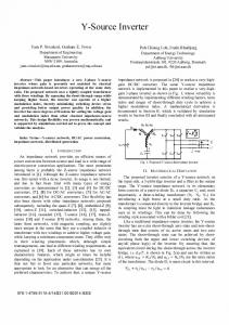
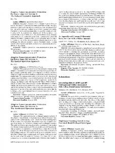
I. INTRODUCTION Since the first publication of the Z-source inverter (ZSI) in 2003, there have been numerous research efforts to improve performances of the ZSI in both circuit topology and control method [1-11]. The trans-Z-source inverters, which employ a transformer (or coupled inductor) in the impedance network, have been published recently to overcome limited voltage gain of the ZSIs or qZSIs by changing turns ratio of the coupled inductor (or transformer) [12,13]. Fig. 1(a) shows the original voltagefed (VF)-ZSI and Fig. 1(b) shows the VF-qZSI. In (q)ZSIs shown in Fig. 1, the two inductors in the Zsource network (L1, L2) can be non-coupled or coupled. Due to the structural constraint of the Z-source network, however, voltages across the two inductors must be same. Therefore, if L1 and L2 are coupled, then turns ratio (n) of the coupled inductor should be 1:1. However, if either C1 or C2 is removed from the circuit in Fig. 1(b), L1 and L2 are no longer to be coupled to 1:1. It can be coupled with arbitrary turns ratio [13]. Fig. 2(a) and (b) show the VF-trans-qZSI with C2 or C1 is removed, respectively from the circuit in Fig. 1(b). By changing turns ratio (n) of the coupled inductor to more than 1, voltage gain of the VF-trans-qZSI can be increased more than that of VF-qZSI shown in Fig. 1(b). The dc link voltage in the non-shoot-through states (Vpn) is expressed as follows [13]
(b) VF-qZSI Fig. 1. VF-ZSI and VF-qZSI
L2
L1
D n :1
Vin
V pn
C1
(a) VF-trans-qZSI with C2 removed
C2 L2
D
L1
1: n
V pn
Vin
(b) VF-trans-qZSI with C1 removed Fig. 2. VF trans-Z-source inverters
V pn
1 Vin 1 � (1 � n) Dsh
(1)
978-1-61284-957-7/11/$26.00 ©2011 IEEE
,where Dsh is shoot-through duty ratio and n is turns ratio of the coupled inductor. Similarly, voltage across the capacitors C1 and C2 in Fig. 2 are expressed as follows; VC1
1 � Dsh Vin 1 � (1 � n ) Dsh
VC 2
nDsh Vin 1 � ( n � 1) Dsh
(2)
windings of each coupled inductors (L1b, L2b, …, LNb) are connected in series with diodes (D1, D2, …, DN) and they are connected in parallel with capacitors (C1, C2, …, CN). With this configuration, all the capacitor voltages (Vc1, Vc2, …, VcN) in the Z-source network are added together and therefore Vx is expressed as follows N
Vx
(3)
If n=1, Vpn, Vc1 and Vc2 become same as the voltage of the VF-qZSI shown in Fig. 1(b). The main benefits of the trans-Z-source inverters are as follows; y Like the ZSIs or qZSIs, it can be short- and opencircuited without damaging switching devices. Therefore, it is very resistant to EMI noise. y It can obtain a higher voltage gain with the same shoot-through duty cycle than the (q)ZSIs by making turns ratio of the coupled inductor to more than one. This paper extends application of the VF-trans-Zsource inverter to parallel operation of inverter. Generally, parallel operation of inverter has many advantages such as modularity, ease of maintenance, (n+1) redundancy, high reliability, etc [14-17]. In addition to these, output current ripple ( io ) of the paralleled inverter can be reduced significantly by virtue of interleaving effect. Fig. 3 shows general circuit configuration of two paralleled voltage source inverter (VSI).
io
¦Vcj
(4)
j 1
,where Vcj ( j 1, 2,..., N ) is the voltage across each capacitor in the Z-source network. Therefore, the desired high voltage gain can be obtained even with small coupled inductor turns ratio (n). If Vcj’s are assumed to be equal to each other and defined as Vc, then Vx becomes Vin+NVc. Therefore, the voltage across each capacitor is (Vx-Vin)/N. From the flux balance condition on each coupled inductor, voltage gain of the proposed VF-trans-Z-source inverter is expressed as follows; § · 1 � Dsh ¨ ¸ Vin © 1 � ( Nn � 1) Dsh ¹
Vx Vc
(Vx � Vin ) N V pn
V pn
nDsh Vin 1 � ( Nn � 1) Dsh § 1 ¨ © 1 � Dsh
· ¸ Vx ¹
1 1 � ( Nn � 1) Dsh
Vin
Vdc
Vin �
(5)
(6)
(7)
(8)
,where Dsh represent shoot-through duty cycle of inverter, N is the number of inverter paralleled, and n is turns ratio of the coupled inductor. From (5)-(8) and by defining the output peak phase voltage and modulation index as Vm and M, respectively, ac
output voltage of the proposed inverter is expressed as (9) Vm ac Fig. 3. Parallel operation of VSI
Fig. 4 shows basic concept of the proposed N-parallel connected VF-trans-Z-source inverter. (L1a, L1b), (L2a, L2b), …, and (LNa, LNb) represent primary and secondary inductance of each coupled inductor. Primary windings of each the coupled inductors (L1a, L2a, …, LNa) are connected between point “X” (see Fig. 4) and switching devices of each inverter, whereas secondary
V pn 2
MB
Vin 2
(9)
1 (10) 1 � ( Nn � 1) Dsh ,where B is the boost factor. As shown in Fig. 4 each inverter’s output is connected together after the output filter inductors. If interleaved switching method is used, gate signals in each inverter are shifted by 360/N degree. As a result of interleaving, the output current ripple can be reduced significantly. In this paper, however, non-interleaved switching method (no phase shift) is simply used to verify operating principle of the proposed parallel VF-trans-Z-source inverter. Although the interleaved switching method B
II. PARALLEL OPERATION OF VF-TRANS-Z-SOURCE INVERTER
M
Vc 2
VcN
Vc1
C2
CN
D2
DN L Nb
C1 L2b
Vin
VX
Vin �
D1
L1b " X "
L1a
V pn1
N
L1
j 1
L2a
¦Vcj
V pn 2
L1 LNa
V pnN
Fig. 4. General circuit configuration of the proposed N-parallel connected VF-trans-Z-source inverter
C2
C1
i pn1
D2 L 2b Vin
D1
L1b
ia1
L1a
n 1
n 2
V pn1
VX
ia
io
i pn 2 L2a
ia 2
V pn 2
(a) Two paralleled VF-trans-ZSI
(b) Voltage gain vs. M (N=2)
Fig. 5. Two parallel connected VF-trans-ZSI and its voltage gain (MB) vs. M (N=2)
mentioned above can readily be applied to the proposed scheme, it is not considered here because it is out of the scope of this paper. In this paper, two inverter modules are paralleled as shown in Fig. 5(a). Fig. 5(b) shows voltage gain of the proposed inverter as a function of M for n=1 and 2 when N=2. Constant boost with 3rd harmonic injection control method is used in this paper [5].
III. EXPERIMENTAL WAVEFORMS A 2.6 kW two paralleled VF-trans-ZSI is built and tested to verify performance of the proposed inverter.
Table I shows detailed electrical specifications of the proposed prototype inverter. TABLE I ELECTRICAL SPECIFICATIONS OF THE PROPOSED INVERTER Output Power 2.6 kW Minimum input voltage 160 Vdc Output voltage 208 Vrms (line-line) L1a, L1b 210 uH Coupled inductor L2a, L2b 210 uH Z-source capacitor (C1, C2) 100 uF IGBT CM100TL_24NF Diode IXYS DSEI 2X61-12B Output filter inductor 660 uH Output filter capacitor 100 uF Switching frequency 10 kHz
For the sake of simplicity, turns ratios of each coupled
inductor are set to 1:1 (n=1). Bifilar winding method using copper foil is employed to minimize leakage inductance and to maximize coupling coefficient of the coupled inductors. Therefore, L1a is almost equal to L1b and L2a is also almost equal to L2b.
normal mode operation (without shoot-through). In this mode, Vin, Vx, and Vpn are all equal since there is no shoot-through.
ia [10 A/div]
Vx [200V/div]
V pn [200 V/div]
ia 2 [5A/div] Vab [200 V/div]
ia1 [5A/div]
I o [20A/div]
[5msec/div]
Fig. 7 Output filter inductor current in boost mode
[5msec/div]
(a)
Vx [200V/div]
V pn [200 V/div]
Vx [200V/div] I pn [20A/div]
V pn [200 V/div]
[10ȝsec/div]
Vab [200V/div]
I o [20A/div]
Fig. 8 Normal mode operation (Vin=300 V, M=1.15, Dsh=0)
(b) Fig. 6. Experimental waveforms of the proposed inverter in boost mode (Constant boost with 3rd harmonic injection control, Vin=160 V, Vab=208 Vrms, M=0.955, Dsh=0.17, Po=2.6 kW, and fsw=10 kHz)
Fig. 6 (a) shows experimental waveforms of the proposed inverter in boost mode operation. Fig. 6 (b) shows the expanded waveforms of the dc link current (Ipn) and voltage (Vpn) waveforms of inverter #1. The Ipn and Vpn waveforms of the inverter #2 are exactly the same as those of the inverter #1. Fig. 7 shows current waveforms of the output filter inductor (see labels in Fig. 5) of each inverter. The two current waveforms ( ia1 , ia 2 ) are almost identical and they are exactly half of the total output current ( ia ). Fig. 8 is experimental waveforms of the proposed inverter in
[5msec/div]
Fig. 9 Prototype picture
IV. CONCLUSIONS In this paper, parallel operation of the power converter using the VF-trans-Z-source inverter is introduced. With this configuration, the proposed inverter has the following features. x The proposed inverter has all the advantages of paralleling power converters such as modularity, ease of maintenance, (n+1) redundancy, high reliability, etc. x It can be short- and open-circuited without damaging switching devices. Therefore, it is very resistant to EMI noise and therefore its robustness and reliability are significantly improved. x Voltage gain of the proposed inverter can be increased by increasing either turns ratio of the coupled inductor (n) or number of paralleled inverter (N). A 2.6 kW prototype consisting of two parallel inverters has been built and successfully tested to verify operation principle of the proposed inverter. By increasing the number of modules (N), the proposed concept can be applied to very high power inverters.
REFERENCES F. Z. Peng, "Z-source inverter," Industry Applications, IEEE Transactions on, vol. 39, no. 2, pp. 504-510, 2003. [2] J. Anderson and F. Z. Peng, "Four quasi-Z-Source inverters," in Power Electronics Specialists Conference, 2008. PESC 2008. IEEE, 2008, pp. 2743-2749. [3] T. Yu, X. Shaojun, Z. Chaohua, and X. Zegang, "Improved ZSource Inverter With Reduced Z-Source Capacitor Voltage Stress and Soft-Start Capability," Power Electronics, IEEE Transactions on, vol. 24, no. 2, pp. 409-415, 2009. [3] M. Shen, A. Joseph, J. Wang, F. Z. Peng, and D. J. Adams, "Comparison of Traditional Inverters and Z -Source Inverter for Fuel Cell Vehicles," Power Electronics, IEEE Transactions on, vol. 22, no. 4, pp. 1453-1463, 2007. [4] F. Z. Peng, M. Shen, and Z. Qian, "Maximum boost control of the Z-source inverter," Power Electronics, IEEE Transactions on, vol. 20, no. 4, pp. 833-838, 2005. [5] M. Shen, J. Wang, A. Joseph, F. Z. Peng, L. M. Tolbert, and D. J. Adams, "Constant boost control of the Z-source inverter to minimize current ripple and voltage stress," Industry Applications, IEEE Transactions on, vol. 42, no. 3, pp. 770-778, 2006. [6] C. J. Gajanayake, L. F. Lin, G. Hoay, S. P. Lam, and S. L. Kian, "Extended Boost Z-Source Inverters," Power Electronics, IEEE Transactions on, vol. 25, no. 10, pp. 2642-2652, Oct. 2010. [7] F. Gao, L. Poh Chiang, R. Teodorescu, and F. Blaabjerg, "DiodeAssisted Buck-Boost Voltage-Source Inverters," Power Electronics, IEEE Transactions on, vol. 24, no. 9, pp. 2057-2064, 2009. [8] M. Zhu, K. Yu, and F. L. Luo, "Switched Inductor Z-Source Inverter," Power Electronics, IEEE Transactions on, vol. 25, no. 8, pp. 2150-2158, Aug 2010. [9] H. Xu, F. Z. Peng, L. Chen, and X. Wen, "Analysis and de sign of Bi-directional Z-source inverter for electrical vehicles, " in Applied Power Electronics Conference and Exposition, 2 008. APEC 2008. Twenty-Third Annual IEEE, 2008, pp. 1252 -1257. [10] S. Yang, F. Z. Peng, Q. Lei, R. Inoshita, and Z. Qian, “Cur rent-Fed Quasi-Z-Source Inverter With Voltage Buck-Boost a nd Regeneration Capability,” IEEE Transaction on Industry A pplications, vol. 47, No. 2, pp. 882-892, Mar./Apr. 2011. [11] M. Shen and F. Z. Peng, "Operation Modes and Characteristics of the Z-Source Inverter With Small Inductance or Low Power Factor," Industrial Electronics, IEEE Transactions on, vol. 55, no. [1]
1, pp. 89-96, 2008. [12] R. Strzelecki, M. Adamowicz, N. Strzelecka, and W. Bury, "New type T-Source inverter," in Compatibility and Power Electronics, 2009. CPE '09., 2009, pp. 191-195. [13] W. Qian, F. Z. Peng, and H. Cha, "Trans-Z-Source Inverters," in International Power Electronics Conference, 2010. IPEC 2010. pp. 1874-1881. [14] Satoshi Ogasawara, Jin Takagaki, Hirofumi Magi, and Akira Nabae, A novel control scheme of a parallel current-controlled PWM inverter, IEEE Trans. on Industry Applications, vol.28, no.5, Sept., 1992, pp.1023-1030. [15] Keiju Matsui, Yoshihiro Murai, Makoto Watanabe, Mitsutaka Kaneko, and Fukashi Ueda, A pulsewidth-modulated inverter with parallel connected transistors using current-sharing reactors, IEEE Trans. on Power Electronics, vol. 8, no. 2, April 1993, pp.186-191. [16] Fukashi Ueda, Keiju Matsui, Masahiro Asao, and Kazuo Tsuboi, Parallel-connections of pulsewidth modulated inverters using current sharing reactors, IEEE Trans. on Power Electronics, vol. 10, no. 6, November 1995, pp.673-679. [17] Keiju Matsui, Yasutaka Kawata, and Fukashi Ueda, Application of parallel connected NPC ̽ PWM inverters with multilevel modulation for AC motor drive, IEEE Trans. on Power Electronics, vol. 15, no. 5, September 2000, pp.901-907.


![[WeE1-1] Parallel Operation of Trans-Z-Source Inverter - IEEE Xplore](https://m.moam.info/img/260x300/wee1-1-parallel-operation-of-trans-z-source-invert_5b7efa54097c47c9278b45a1.jpg)