Abstract. Many vision applications require precise measurement of scene radiance. The function relating scene radiance to image brightness is called the ...
What is the Space of Camera Response Functions?∗ Michael D. Grossberg and Shree K. Nayar Department of Computer Science, Columbia University New York, New York 10027 E-mail: {mdog, nayar}@cs.columbia.edu Abstract Many vision applications require precise measurement of scene radiance. The function relating scene radiance to image brightness is called the camera response. We analyze the properties that all camera responses share. This allows us to find the constraints that any response function must satisfy. These constraints determine the theoretical space of all possible camera responses. We have collected a diverse database of real-world camera response functions (DoRF). Using this database we show that real-world responses occupy a small part of the theoretical space of all possible responses. We combine the constraints from our theoretical space with the data from DoRF to create a low-parameter Empirical Model of Response (EMoR). This response model allows us to accurately interpolate the complete response function of a camera from a small number of measurements obtained using a standard chart. We also show that the model can be used to accurately estimate the camera response from images of an arbitrary scene taken using different exposures. The DoRF database and the EMoR model can be downloaded at http://www.cs.columbia.edu/CAVE.
1
Scene Radiance to Image Brightness
Researchers in computer vision develop algorithms to determine scene properties like shape, reflectance, and illumination from images. Many of these algorithms require precise measurements of scene radiance to recover the scene properties. Examples of algorithms that explicitly use scene radiance measurements are color constancy [7, 13], construction of linear high dynamic range images [17, 4, 16], photometric stereo [2, 18, 20], shape from shading [12], estimation of reflectance and illumination from shape and brightness [14], recovery of BRDF from images [5], and surface reconstruction using Helmholtz stereopsis [21]. What connects scene radiance with image brightness? The optics of the imaging system gather light rays from scene points and focus the rays on the image plane [11]. An electronic or chemical photo-detector converts image irradiance to image brightness1 . ∗ This
work was completed with support from a National Science Foundation ITR Award (IIS-00-85864) and a grant from the Human ID Program: Flexible Imaging Over a Wide Range of Distances Award No. N000-14-00-1-0929 1 To simplify our exposition, we include integration time in ir-
The goal of this work is to provide an accurate and convenient model of the mapping from scene radiance to image brightness. In general, this mapping comprises several complex factors, such as vignetting, lens fall-off, the sensitivity of the detector, and the electronics of the camera [1, 10]. Regardless of the individual factors involved, we can assume the mapping is a composite of just two functions, s and f , as shown in Fig. 1. The function s models the effect of transmission through the optics of the system. It may vary spatially over the image but is generally linear with scene radiance [1]. The function f models the process by which the irradiance E of an image point is converted to an image brightness B. This f is generally a non-linear function of image irradiance and is called the camera response function. In many imaging devices, the non-linearity of f is intentional. A non-linear mapping is a simple means to compress a wide range of irradiance values within a fixed range of measurable image brightness values. Manufacturers produce photographic films with specific nonlinear characteristics. The responses of digital cameras are often designed to mimic the non-linearities of film. Though non-linear, a camera’s response function is generally uniform across the spatial dimensions of the image. Hence, it is described by a one-variable function of irradiance, B = f (E). Inversion of the camera response function allows the transformation of image brightness to image irradiance. Going from image irradiance to scene radiance can then be accomplished by finding s, which is easy to do once f is known [1, 10]. Therefore, we will focus our attention on the response function f . A number of algorithms have been introduced in computer vision and computer graphics to estimate the camera response f from multiple images of a scene taken with different exposures [4, 15, 16, 17, 19]. All these methods make a priori assumptions about the form of the response function2 . For example, by assuming the response has the form of a gamma curve, f (E) = α + βE γ , Mann and Picard [16] find the parameters γ, α, and β from multiple registered images of a static scene taken using different exposures. Mann also proposed other analytic forms for the response [15]. ˜ where t is the integration time and E ˜ radiance E. Thus, E = tE, is the irradiance per unit time. 2 It was recently shown in [8] that, to avoid ambiguities, a priori constraints on the response function are imperative when finding the response from multiple images.
Proceedings of the 2003 IEEE Computer Society Conference on Computer Vision and Pattern Recognition (CVPR’03) 1063-6919/03 $17.00 © 2003 IEEE
Scene Radiance L
Linear Function (optical effects)
s
Image Irradiance E
Non-Linear Response (electronics or film)
f
Image Brightness B
Figure 1: Flow diagram showing the two basic transformations, s and f, that map scene radiance L to
image brightness B. The function s models the optics of the imaging system. It may vary spatially but is generally linear. The mapping f of image irradiance to image brightness is called the camera response function. It is usually non-linear but can be assumed to be spatially uniform.
One difficulty with such assumptions is that a camera’s response function can vary significantly from an analytic form like a gamma curve. In [4] and [19], no particular form is assumed. Instead they impose smoothness constraints. In a compromise between these two extremes, Mitsunaga and Nayar [17] assume that a lowdegree polynomial is a sufficiently general parameterized model of response functions. It is important to note that, while a lot of recent work acknowledges the importance of camera response, a careful analysis and modeling of the response has yet to be done. We wish to address this void. In doing so, we seek answers to the following fundamental questions: • What is the space of possible camera response functions? We show that all response functions must lie within a convex set that results from the intersection of a plane and a positive cone in function space. This gives us both guidance on the form of our model as well as constraints. • Which camera response functions within this space arise in practice? We created a Database of Response Functions (DoRF) of a variety of films and solid-state cameras that are available in the market. The database currently includes a total of 201 real-world response functions. • What is a good model for response functions? We combine the constraints from our analysis, and the data from DoRF to formulate a new Empirical Model of Response (EMoR) which can model a wide gamut of response functions with a very small number of parameters. We show that EMoR outperforms alternative models, including previously used ones, in terms of accuracy. We show that EMoR works well by using a number of different evaluation metrics. We demonstrate that EMoR can be used to recover complete response functions from an image of a chart with a few known reflectances. It can also be used to accurately determine a camera’s response from a set of images of a scene taken at different exposures. We have made the DoRF database and the EMoR model available at http://www.cs.columbia.edu/CAVE.
2
What is the Theoretical Space of Camera Response Functions?
Before we explore the theoretical space of response functions, we state our assumptions: • Our first assumption is that the response function f is the same for all pixels on the detector. Linear spatial variations in the response, such as fixed pattern noise [10], can be folded into the function s (see Fig. 1) which includes effects such as lens fall-off [1]. By removing such variations, the response becomes a one-variable function of image irradiance, f (E) = B, where B is image brightness. • Our second assumption is that the range of our camera’s response goes from BMIN to BMAX . These values are easily computed.3 The units of response are arbitrary, so we normalize the response so that BMIN = 0 and BMAX = 1. • Our third assumption is that the response function is monotonic. If the response is not monotonic, it is many to one and thus cannot be linearized. This limits its usefulness in computer vision. Without loss of generality, we assume f monotonically increases.4 This implies that corresponding to BMIN and BMAX are minimum and maximum detectible irradiances, EMIN and EMAX . These parameters also can be incorporated into the function s in Fig. 1, since they represent a linear scaling and shift along the irradiance axis. Therefore, we normalize irradiance so that EMIN = 0 and EMAX = 1. With these assumptions, we define the theoretical space of camera response functions as: WRF
:=
{f |f (0) = 0, f (1) = 1, and f monotonically increasing }.
The exact form of the space WRF is easier to understand in terms of vectors. Any function f of irradiance (not necessarily a response) may be thought of as a vector by sampling it at a set of fixed increasing irradiance levels. That is, the function f becomes the finite-dimensional 3 For example, in digital cameras B MIN is the mean of the thermal noise. This may be estimated from an image taken with the lens cap on. 4 If it decreases we use 1 − f as our response.
Proceedings of the 2003 IEEE Computer Society Conference on Computer Vision and Pattern Recognition (CVPR’03) 1063-6919/03 $17.00 © 2003 IEEE
3
W
:
0
BP
=
0
Λ: Solid cone
W
f
:
1
BP
=
1
WRF: Response functions
Even though the theoretical space of response functions WRF is restricted to an intersection of a plane and a cone, it is still infinite-dimensional. However, there are a limited number of processes that are used in films and in solid state detectors to collect light. As a result, many functions within the theoretical space never arise in practice. It therefore makes sense to look for a finitely parameterized subset of WRF which approximates the set of real-world response functions.
h
f0
BP
Figure 2: To visualize the theoretical space of camera response functions we represent the response functions as vectors. Vectors that satisfy f (1) = 1 lie on the plane W1 . Vectors satisfying the monotonic condition lie in the shaded solid polygonal cone Λ. The theoretical space WRF of camera response functions is the darkly shaded intersection Λ ∩ W1 .
vector5 (B1 , . . . , BP ) = (f (E1 ), . . . , f (EP )). We set the brightest sampled irradiance to be EP = 1. If f is a response function, it is normalized such that at irradiance 1 it has maximum brightness BP = f (1) = 1. Therefore, all response vectors must lie in the plane W1 shown in Fig. 2, where the last component BP is 1. If f and f0 are any two response vectors in the plane W1 , the difference h = f − f0 lies in a parallel plane W0 going through the origin (see Fig. 2). Therefore, any response function can be expressed as f = f0 +h where f0 is some base response function and h ∈ W0 . Now, we have the additional constraint that a response function is monotonic, which means that its first derivatives must be positive. Any positive linear combination of two functions with positive derivatives must also have positive derivatives. We know that a set is a cone when it has the property that positive linear combinations of its elements lie within it. Therefore, monotonic functions can be represented by a cone, shown as Λ in Fig. 2. Combining both of the above constraints, we see that the theoretical space of all response functions WRF is the intersection (the darkly shaded region in Fig. 2) of the cone Λ with the plane W1 : WRF = W1 ∩ Λ.
Approximation Models for the Response Function
(1)
Note that the convexities of the plane and the cone imply that the intersection WRF is also convex. As a consequence the mean of any set of camera response functions is also a valid camera response function. 5 We will treat f interchangeably as a vector and a function. We assume the function f is smooth enough so that we can recover it from a vector of dense samples by interpolation.
To find a parametrization of WRF we use the description we obtained in Eq. 1, and note that W1 = f0 + W0 . We observe that any choice of basis h1 , h2 , . . . for the vector space W0 gives an approximation model.6 The first M basis elements give the M th order approximation: f0 (E) +
M �
cn hn (E) ,
(2)
n=1
where c1 , . . . , cM are the coefficients or parameters of the model.7 This approach generalizes that of Mitsunaga and Nayar [17] which uses a polynomial basis to approximate WRF . In our notation in Eq. (2), the polynomial model is obtained using f0 (E) := E and hn (E) := E n+1 − E. One can also obtain a trigonometric approximation model by using f0 (E) := E and the half-sine basis hn (E) := sin(nπE). Clearly, there are many more choices. Thus, while the description of WRF in Sec. 2 in terms of W0 and f0 has suggested the general form of an approximation model, it has not given us criteria to decide which basis of W0 to use. The efficiency of any basis depends on how close the responses of actual imaging systems are to the space spanned by the first few basis elements. Hence, a natural approach is to use the response curves of real-world imaging systems to determine the appropriate basis for the approximation model.
4
Real-World Response functions
We gathered response curves for a wide variety of photographic films, CCD sensors, and digital cameras (detector + electronics). Companies such as Kodak, Agfa, and Fuji have published response curves for some of their films on their web sites. The curves we gathered include representatives from positive and negative films, consumer and professional films, still and motion picture films, in both color as well as black and white. We treated the three response curves for color films as three different responses. We also included curves of the same film type but different ASA speeds. Examples of film brands we included are Agfacolor Futura, Agfachrome 6 We
have also considered a log-space version, for details see [9]. that due to normalization of f in Sec. 2 the model implicitly has the scale and offset parameters BMIN , BMAX , EMIN , and EMAX . 7 Note
Proceedings of the 2003 IEEE Computer Society Conference on Computer Vision and Pattern Recognition (CVPR’03) 1063-6919/03 $17.00 © 2003 IEEE
Cannon Optura Kodak DCS 315 Green 0.9 Sony DXC-950 1
0.8 0.7 0.6 0.5 0.4 0.3 0.2
Normalized Brightness
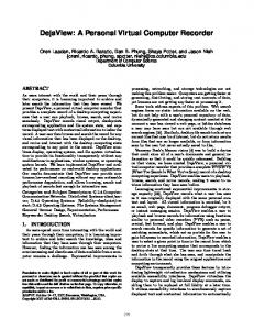
Kodak Ektachrome-100plus Green Kodak Ektachrome-64 Green Agfachrome CTPrecisa100 Green Agfachrome RSX2 050 Blue Agfacolor Futura 100 Green Agfacolor HDC 100 plus Green Agfacolor Ultra 050 plus Green Agfapan APX 025 Agfa Scala 200x Fuji F400 Green Fuji F125 Green Kodak Max Zoom 800 Green Kodak KAI0372 CCD Kodak KAF2001 CCD
gamma curve, γ =0.6
0.1 gamma curve, γ =1.0 0
0.1
0.2
0.3
0.4
0.5
0.6
0.7
0.8
0.9
1
0
gamma curve, γ =1.4 gamma curve, γ =1.8
Normalized Irradiance
Figure 3: Examples from our database of 201 real-world response functions (DoRF). The database includes photographic films, digital cameras, CCDs, and synthetic gamma curves. Note that even within a single brand of film, for example Agfa, there is considerable variation between response curves. RSX-II, Fuji F125, Fuji FCICD, Kodak Advantix, Kodak Gold, and Kodachrome. We also obtained response curves for several CCD sensors, in particular Kodak’s KAI and KAF series. In the case of digital cameras, the manufacturers we contacted were unwilling to provide the responses of their cameras. However, Mitsunaga and Nayar have measured the responses of a variety of digital and video cameras, including the Sony DXC 950 and the Canon Optura using their algorithm RASCAL [17]. These curves were included. Many camera manufacturers design the response to be a gamma curve. Therefore, we included a few gamma curves, chosen from the range 0.2 ≤ γ ≤ 2.8, in our database. Currently, the database contains a total of 201 curves, a few of which are shown in Fig. 3. As we discussed in Sec. 2, we assume that response curves are monotonic. For this reason, the 201 response curves we chose were all monotonic. The few nonmonotonic ones we came across were disregarded. In the case of negative film, we transformed the curves to make them monotonically increasing rather than monotonically decreasing. All curves were converted to linearlinear scale in response and irradiance.
5
An Empirical Model of Response
In this section, we present a new model for the camera response which combines the general form of the approximation model of Eq. (2) with the empirical data in the DoRF database described in Sec. 4. To create as well as test such a model, we segregated the DoRF database into a training set of 175 response curves and a testing set with 26 curves. We denote the training curves as {g1 , . . . , gN } ⊂ WRF , where N = 175 and WRF is the theoretical space of responses defined in Sec. 2. We would like to find a low dimensional approximation of WRF , based on our linear model from Eq. (2), that is
close8 to the empirical data from DoRF. We can achieve this by applying Principal Component Analysis (PCA) to the training curves to find a basis {h1 , h2 , . . . , hM } for Eq. (2). We will refer to this basis as the Empirical Model of Response (EMoR). Recall from Sec. 2 that WRF is a convex set. This implies �N that the mean curve (1/N ) n=1 gn is also a response function. We choose f0 in Eq. (2) to be the mean curve, which is shown in Fig. 4(a). It represents the 0th order approximation to WRF . To find the basis of Eq. (2) using PCA, we work with a finite-dimensional approximation. By densely sampling each response curve f at points {E1 , . . . , EP }, we approximate f by the vector (f (E1 ), . . . , f (EP )). Using all the response vectors in our training set, the elements of its symmetric covariance matrix C are found as: Cm,n =
N �
(gp (En ) − f0 (En ))(gp (Em ) − f0 (Em )).
p=1
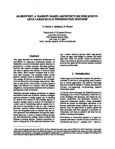
We write VM for the span of the eigenspaces associated with the largest M eigenvalues of the matrix C. The space VM is the best M -dimensional approximation to the space W0 [6]. The curves in Fig. 4(b) are the eigenvectors for the 4 largest eigenvalues of the covariance matrix C. The cumulative energies associated with the eigenvalues increase rapidly, as seen in Fig. 4(c). This shows that EMoR represents the space of response functions well. In fact, 3 eigenvalues explain more than 99.5% of the energy. This suggests that even a 3-parameter model should work reasonably well for most response functions found in practice. To approximate a new response function f in WRF with an M -parameter EMoR, we project f − f0 ∈ W0 into 8 For
simplicity, we use the root mean square distance.
Proceedings of the 2003 IEEE Computer Society Conference on Computer Vision and Pattern Recognition (CVPR’03) 1063-6919/03 $17.00 © 2003 IEEE
0.8 0.6 0.4 0.2 0
0
0.2
0.4
0.6
0.8
1
0.06 0.04 0.02 0 -0.02 -0.04 -0.06 -0.08 -0.10
Normalized Irradiance (a)
h3
Percent of Energy
Normalized Brightness
Normalized Brightness
1
h2 h4 h1 0
0.2
0.4
0.6
0.8
1
100 98 96 94 92 90 88 86 84 82 80
1
2
Normalized Irradiance (b)
3
4
5
6
7
8
9 10
Principal Components (c)
Figure 4: (a) The mean of 175 camera responses in DoRF used as the base curve f0 in the EMoR model. (b) Four eigenvectors (functions) corresponding to the largest four eigenvalues of the covariance matrix for the 175 curves. (c) A plot showing the percentages of the energies captured by VM , the span of the M principal components. The subspace corresponding to the three largest eigenvalues (an EMoR model with 3 parameters) captures more than 99.5% of the energy. VM . Let H := [h1 · · · hM ] be the matrix whose columns are the first M unit eigenvectors. Then, the EMoR approximation f˜ to the response curve f is (3)
T
where c = H (f − f0 ) are the model coefficients.
6
Imposing Monotonicity
The EMoR approximation f˜ satisfies the constraint f˜ ∈ W1 . Nevertheless, as discussed in Sec. 2, functions in the theoretical space WRF must also be monotonic. To impose this constraint on the EMoR approximation, we need to find the best monotonic approximation f˜mon to the true response curve f . In other words, we find the closest point in LM := (f0 + VM ) ∩ WRF to f where we measure distance in terms of the norm in L2 . The space LM is convex since it is an intersection of convex sets. Hence, there must be a unique closest point in LM to f. A function f˜mon is monotonic if its derivative is positive. If D is the discrete derivative matrix then we wish to ensure that Df˜mon ≥ 0. Again, let H be the matrix with the first M PCA eigenvectors as columns. Then, f˜mon will be of the form f˜mon = f0 + H cˆ, where the coefficient vector cˆ is determined as cˆ = arg minc ||Hc − f − f0 ||2 , subject to the constraint DH cˆ ≥ −f0 . (4) Thus, finding cˆ turns into a standard problem of quadratic programming (see [9] for details.) Solving this problem gives us the best monotonic EMoR approximation for any response curve.
7
Evaluating the EMoR Model
The various approximation models described in Sec. 3 can fit arbitrarily complex response functions at the cost of using many parameters (model coefficients). What distinguishes these models from each other is the rate
Dim 1 Dim 3 Dim 5 Dim 7 Dim 9 curve
1
Normalized Brightness
f˜ = f0 + Hc
1.2
0.8
Agfa Scala 200 ASA
0.6 0.4
gamma curve, g= 2.4
0.2 0 -0.2
0
0.1
0.2
0.3
0.4
0.5
0.6
0.7
0.8
0.9
1
Normalized Irradiance
Figure 5: A qualitative illustration of how the fit of the EMoR model improves with the numbers of model parameters. Here, we show two of the most difficult responses in the DoRF database. For each of these responses, approximation curves with 1, 3, 5, 7, and 9 parameters are shown. Even with 5 parameters the approximation is quite good. With 11 parameters there is little difference between the approximate and actual curves.
and manner with which the quality of the approximation varies with the number of parameters. To see this in the case of EMoR, we chose two curves from the DoRF database which were difficult to fit. Fig. 5 shows approximations of these two curves with the number of parameters M = 1, 3, 5, 7, and 9. Even the low-parameter approximations follow the curves grossly. With 5 parameters, it is hard to distinguish the response curves from the approximations. The approximations for M = 11 are almost identical to the original curves. These worstcase curves show qualitatively how fitting improves with the number of parameters.
Proceedings of the 2003 IEEE Computer Society Conference on Computer Vision and Pattern Recognition (CVPR’03) 1063-6919/03 $17.00 © 2003 IEEE
RMSE Training Case data Disparity Case RMSE Testing Case data Disparity Case
Dim Mean Error Worst Curve Mean Error Worst Curve Mean Error Worst Curve Mean Error Worst Curve
1 4.12E-02 2.34E-01 9.07E-02 3.43E-01 4.00E-02 2.04E-01 8.28E-02 2.88E-01
2 3 4 5 1.94E-02 8.87E-03 4.15E-03 2.82E-03 1.37E-01 6.49E-02 2.48E-02 1.76E-02 4.77E-02 2.60E-02 1.51E-02 1.05E-02 2.41E-01 2.06E-01 1.64E-01 1.31E-01 1.73E-02 6.27E-03 2.54E-03 1.77E-03 1.06E-01 3.79E-02 9.47E-03 9.38E-03 3.62E-02 1.74E-02 1.02E-02 7.58E-03 1.56E-01 6.75E-02 3.19E-02 2.23E-02
6 1.91E-03 1.29E-02 8.09E-03 1.02E-01 1.07E-03 3.56E-03 5.65E-03 2.16E-02
7 1.58E-03 1.08E-02 7.46E-03 9.81E-02 9.55E-04 2.78E-03 5.49E-03 2.15E-02
8 1.15E-03 8.08E-03 4.96E-03 5.37E-02 6.37E-04 1.90E-03 3.14E-03 1.61E-02
9 9.10E-04 6.39E-03 4.30E-03 4.05E-02 5.23E-04 1.75E-03 2.75E-03 1.37E-02
10 7.60E-04 4.53E-03 3.95E-03 3.93E-02 4.74E-04 1.62E-03 2.62E-03 1.36E-02
11 6.02E-04 2.94E-03 3.12E-03 2.56E-02 4.00E-04 1.60E-03 2.04E-03 8.21E-03
Table 1: An evaluation of the performance of the EMoR model as the number of parameters increase. The model was used to approximate curves in our training set of 175 curves and testing set of 26 curves from DoRF. In the RMSE Case, the Mean Error is the RMSE averaged over all the curves in each set. The largest RMSE for the set is listed in the row labeled Worst Curve. The Disparity Case uses the maximum disparity between approximated and actual curves. In this case, the Mean Error and the Worst Curve values are the mean disparity and maximum disparity computed over all the curves in the set. Most curves are well approximated using only 3 parameters. dim model gamma polynomial trigonometric EMOR
1 3.46E-02 7.37E-02 6.83E-02 4.00E-02
2 N. A. 3.29E-02 3.91E-02 1.73E-02
3 N. A. 1.71E-02 2.58E-02 6.27E-03
RMSE case 4 N. A. 1.06E-02 1.89E-02 2.54E-03
5 N. A. 6.93E-03 1.44E-02 1.77E-03
6 N. A. 4.95E-03 1.16E-02 1.07E-03
7 N. A. 3.65E-03 9.46E-03 9.55E-04
Table 2: Table showing RMSE of various approximation models averaged over the testing curves. To compute accuracy in bits, take −log2 of the average RMSE. EMoR clearly outperforms all the other models. We conducted an extensive quantitative evaluation of the EMoR model. Table 1 shows how accuracy increases with dimensionality. We used EMoR to approximate the 175 training curves as well as the 26 testing curves described in Sec. 4. We used four metrics with each set to evaluate the results. The results are shown in Table 1. The error values based on root-mean-square error (RMSE) appear in rows labeled RMSE Case. We compute the Mean Error by averaging the RMSE over all curves in each set (training and testing). The largest RMSE over all curves in the set gives the value called Worst Curve. The errors in rows labeled Disparity Case are computed from the maximum disparity of the fit and the original curve. The columns of Table 1 correspond to the dimensions (parameters) used for the EMoR model. Note that most curves are well approximated using an EMoR model with just three parameters.
We also evaluated EMoR by comparing its performance to other approximation models, when monotonicity is imposed in all cases. These include the gamma function, E γ , as well as the polynomial and trigonometric approximation models described at the end of Sec. 3. The gamma curve has only one parameter, given our normalizations. Table 2 summarizes our results for the DoRF testing curves. The accuracy of the gamma curve model, using the RMSE averaged across the testing curves, is 4.86 bits. For one-parameter models, the gamma curves are superior to other models. All models, except the gamma curve, may be made more accurate by using more parameters. As the number of parameters increases, the EMoR based monotonic fit significantly outperforms the other models.
Taking −log2 of the entries in Table 1 gives the accuracy in bits. The number of parameters needed for acceptable accuracy depends on the application. For example, suppose we wish to construct a mosaic by blending a set of images taken with an 8-bit camera, and an error of 4 gray-levels is acceptable. Choosing 3 parameters gives an RMSE Case/Mean Error accuracy of 6.8. In an application that is more sensitive to errors, such as stereo, choosing 6 parameters exceeds 9.0 bits of accuracy using the same measure. Some algorithms may require very accurate scene radiance measurements. The Disparity Case/Mean Error metric gives the average of the worst errors. This measure indicates that using 11 parameters ensures 8.3 bits of accuracy.
The most popular way to estimate a camera’s response function is by imaging a color chart of known reflectances, such as the Macbeth chart [3]. The Macbeth chart includes 6 patches with known reflectances going from white through gray to black. Typically, one applied standard interpolation to these points to obtain a continuous response function. There is no guarantee that the interpolated values correspond to the actual response function of the camera.
8
Camera Response from Sparse Samples
The EMoR model enables us to obtain accurate interpolations from chart measurements. Fig. 6 shows interpolation results obtained by fitting four different 3parameter models (including EMoR) to the sparse re-
Proceedings of the 2003 IEEE Computer Society Conference on Computer Vision and Pattern Recognition (CVPR’03) 1063-6919/03 $17.00 © 2003 IEEE
very few samples.
Camera Response
9
Normalized Brightness
1
A number algorithms recover a camera’s response from multiple images of an arbitrary static scene taken using different exposures [4, 15, 16, 17, 19]. These algorithms recover the inverse response function f −1 = g, where g(B) = E. Since an inverse response function has all the properties of a response function, we can apply PCA to the inverses of the curves in DoRF to get an EMoR representation of the inverse camera response. We write �M g(B) = g0 (B) + n cn hninv (B) in terms of the mean g0 and the eigenvectors hinv of the covariance matrix of n the inverse curves.
0.8
0.6 Monotonic EMoR Monotonic polynomial EMoR Polynomial Chart values used for fit Other chart values
0.4
0.2
0 0
0.1
0.2
0.3
0.4
0.5
0.6
0.7
0.8
Response from Multiple Images
0.9
1
Normalized Irradiance Figure 6: The response curve of a Nikon 990 camera interpolated from sparse samples, obtained using a Macbeth chart, using 3-parameter EMoR and polynomial models both with and without monotonicity imposed. Images of the chart taken with the same camera at different exposures provide the additional measurements (ground truth) used to estimate the accuracies of the interpolations. The monotonic EMoR has the smallest RMS error. sponse samples obtained from an image of a Macbeth chart taken using a Nikon 990 digital camera9 . From the chart and its image, we have six normalized irradiance values E1 , . . . , E6 and corresponding brightness values B1 , . . . , B6 . The 3 coefficients for the EMoR model are computed using Eq. 3, where the matrix H comes from the EMoR basis functions h1 , h2 , and h3 evaluated at E1 , . . . E6 . Similarly, we take the first 3 basis vectors for the polynomial model evaluated at E1 , . . . E6 to obtain H and compute the 3 coefficients of that model. We also computed the first 3 coefficients of the EMoR and the polynomial model with monotonicity imposed, using the method described in Sec. 6. The interpolations obtained from the different models were evaluated (using RMSE) against many more chart measurements obtained by simply changing the camera’s exposure. For the 3-parameter EMoR, the RMSE was 0.11, while for the polynomial model, it was 0.12. Moreover, the polynomial fit is already beginning to exhibit the kind of oscillations one expects from over-fitting. These oscillations worsen as the number of parameters increases. This is because we only fit using 6 data points. When we constrain the fits to be monotonic, the RMSE for the EMoR model is 0.11 and RMSE for the polynomial model is 0.57. In summary, the EMoR model enables accurate reconstructions of response curves from 9 The Nikon 990 camera was not part of the training or testing curves in DoRF.
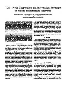
Now, suppose two images of the same scene are captured with exposures e and k · e, where k is the ratio of exposures. Suppose the images are registered. If a response Ba at a point in one image corresponds to a response Bb in the second image, then their irradiances must satisfy g(Ba ) = kg(Bb ). Since the equations g(Ba )−kg(Bb ) = 0 are linear in the coefficients cn , the coefficients can be found using least-squares techniques, when k is known. Using this approach, we recovered the response of the Nikon 990 Coolpix camera from the three images of a scene shown in Fig. 7, taken using exposures e, 2e, and 4e (i.e. k = 2). The monotonic EMoR fit (using just 3 parameters) is shown as a solid curve in Fig. 8. For comparison the polynomial method of Mitsunaga and Nayar [17], and the log method of Debevec and Malik [4] is also shown. Measurements from the Macbeth chart (black dots) are included as ground truth. All the recovered curves are reasonable fits although only the EMoR fit is monotonic. The EMoR fit was found to be closest to the ground truth (chart data).
10
Conclusion
Radiometric response curves represent the critical link between image measurements and scene radiances. In this paper, we have conducted a detailed analysis of the properties of response curves. From these properties, we derived the theoretical space of all camera response functions. We have shown that all responses must lie within a convex set that results from the intersection of a plane and the positive cone of monotonic functions. We used this space to formulate a general approximation model for camera responses. This model subsumes previously used ones such as the polynomial model, as well as others such as the trigonometric model. To fully exploit our theoretical insights, we created a database, DoRF, of 201 real-world response functions. We used the empirical data from DoRF and the general approximation model from our theoretical analysis to develop a powerful approximation model for responses called EMoR. We used several measures to show that the EMoR model performs far better than other models
Proceedings of the 2003 IEEE Computer Society Conference on Computer Vision and Pattern Recognition (CVPR’03) 1063-6919/03 $17.00 © 2003 IEEE
Figure 7: Three images of a static scene taken with a Nikon 990 Coolpix camera using exposures e, 2e, and 4e (left to right). These images were used to recover the inverse response of the camera (see Fig. 8).
[3]
Y.C. Chang and J.F. Reid. RGB Calibration for Color Image-Analysis in Machine Vision. IP, 5(10):1414–1422, October 1996.
[4]
P. E. Debevec and J. Malik. Recovering High Dynamic Range Radiance Maps from Photographs. In Proc. of ACM SIGGRAPH, pages 369–378, 1997.
[5]
P.E. Debevec. Rendering Synthetic Objects into Real Scenes. Proc. of ACM SIGGRAPH, 1998:189–198, July 1998.
[6]
R. Duda, P. Hart, and D. Stork. Pattern Classification, 2nd ed. Wiley, New York, 2000.
[7]
G.D. Finlayson, S.D. Hordley, and P.M. Hubel. Color by Correlation: A Simple, Unifying Framework for Color Constancy. IEEE Trans. on PAMI, 23(11):1209–1221, November 2001.
[8]
M. Grossberg and S. Nayar. What can be Known about the Radiometric Response Function from Images? In Proc. of the ECCV, pages 189–205, 2002.
[9]
M.D. Grossberg and S. K. Nayar. Modeling the Space of Radiometric Response Functions. In Technical Report, In Prep., 2003.
Inverse Camera Response
Normalized Brightness
1 Monotonic EMoR Mitsunaga-Nayar (Polynomial) Debevec-Malik λ = 8 (Log space) Debevec-Malik λ = 32 (Log space) Debevec-Malik λ = 128 (Log space) Data from chart
0.8
0.6
0.4
[10] G. Healey and R. Kondepudy. Radiometric CCD camera calibration and noise estimation. IEEE Trans. on PAMI, 16(3):267–276, March 1994. [11] B. Horn. Robot Vision. The MIT Press, 1986.
0.2
0 0
0.1
0.2
0.3
0.4
0.5
0.6
0.7
0.8
0.9
1
Normalized Irradiance Figure 8: Inverse response curves recovered from the images in Fig. 7 using the monotonic EMoR model (with three parameters), the MitsunagaNayar polynomial model, and the Debevec-Malik log model (with three smoothing parameters, λ = 8, 32, 128). The dots correspond to ground truth obtained by calibration using a Macbeth reflectance chart.
used in the literature. We showed two example applications of the EMoR model. The first used a few patches on a reflectance chart to fully recover the response curve of the camera. The second used EMoR to recover the camera response from three images of an arbitrary scene taken with different exposures. Our experimental results show that the EMoR model provides an accurate and efficient lowparameter model of real-world camera responses. The DoRF database and the EMoR model can be downloaded at http://www.cs.columbia.edu/CAVE.
References [1]
N. Asada, A. Amano, and M. Baba. Photometric Calibration of Zoom Lens Systems. In Proc. of ICPR, page A73.7, 1996.
[2]
R. Basri and D.W. Jacobs. Photometric Stereo with General, Unknown Lighting. In Proc. of CVPR, pages II:374–381, 2001.
[12] B.K.P. Horn and M.J. Brooks. Shape from Shading. MIT Press, 1989. [13] E.H. Land and J.J. McCann. Lightness and Retinex Theory. JOSA, 61(1):1–11, 1971. [14] Q.T. Luong, P. Fua, and Y. Leclerc. The Radiometry of Multiple Images. IEEE Trans. on PAMI, 24(1):19–33, January 2002. [15] S. Mann. Comparametric Equations with Practical Applications in Quantigraphic Image Processing. IP, 9(8):1389–1406, August 2000. [16] S. Mann and R. Picard. Being ’undigital’ with digital cameras: Extending dynamic range by combining differently exposed pictures. In In Proceedings of IS&T, 46th Annual Conference, pages 422–428, 1995. [17] T. Mitsunaga and S. K. Nayar. Radiometric Self Calibration. In Proc. of CVPR, volume 2, pages 374–380, June 1999. [18] S.K. Nayar, K. Ikeuchi, and T. Kanade. Shape from Interreflections. IJCV, 6(3):173–195, August 1991. [19] Y. Tsin, V. Ramesh, and T. Kanade. Statistical Calibration of the CCD Imaging Process. In Proc. of the ICCV, pages I: 480–487, 2001. [20] R.J. Woodham. Photometric Method for Determining Surface Orientation from Multiple Images. Optical Engineering, 19(1):139–144, January 1980. [21] T. Zickler, P.N. Belhumeur, and D.J. Kriegman. Helmholtz Stereopsis: Exploiting Reciprocity for Surface Reconstruction. In Proc. of the ECCV, page III: 869 ff., 2002.
Proceedings of the 2003 IEEE Computer Society Conference on Computer Vision and Pattern Recognition (CVPR’03) 1063-6919/03 $17.00 © 2003 IEEE