Appears in the Proceedings of the Applied Computational Electromagnetics Society (ACES), March 2003.
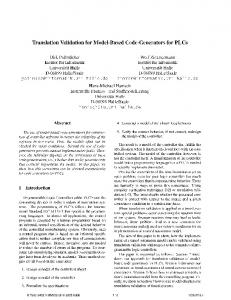
WIPL Code Validation for Metallic Structures Antonije R. Djordjević, Branko M. Kolundžija, Alenka G. Zajić, Marija M. Nikolić, Toma H. Sotirović, and Aleksandra S. Steković
Abstract: There are several sensitive spots in the WIPL analysis of the interdigital microwave filters. If it is not treated properly, the end effect causes significant errors in determination of their central frequencies. Coarse segmentation leads to underestimated coupling among transmission lines. Proper and careful modeling in WIPL can improve the overall accuracy of the numerical results. To that purpose, several metallic interdigital filters have been designed, machined, measured, and modeled by WIPL. The theoretical results were refined with the aim to match experimental data. Hence, guidelines are derived about the required accuracy of integration and approximation in WIPL, as well as subdivision of critical surfaces. The deducted rules can serve in the analysis of similar classes of coupled-line microwave filters, such as combline filters. Keywords: WIPL, Interdigial filters. 1. Introduction The purpose of this paper is to find sensitive spots in the WIPL [1] modeling of the coupled-line microwave filters (interdigital) and to improve overall accuracy. Special attention is paid to the end effect of the resonators, which has significant influence on the resonant frequencies. Many trial-anderror attempts were made to properly model the metallic enclosure. Section 2 presents the metallic interdigital filters treated in this paper. Three filters have been machined, measured, and modeled by WIPL. The computed results were refined to match the experimental data. Section 3 presents several guidelines for the WIPL analysis of interdigital and similar classes of the coupled-line microwave filters, whose aim is to obtain good match between measured and computed data.
Antonije R. Djordjević (
[email protected]), Branko M. Kolundžija, Alenka G. Zajić, and Marija M. Nikolić are with the School of Electrical Engineering, University of Belgrade, King Alexander Blvd. 73, POB 34-54, 11120 Belgrade, Serbia, Yugoslavia. Toma H. Sotirović and Aleksandra S. Steković are with Imtel Microwaves, M. Pupin Blvd. 165b, 11071 Belgrade, Serbia, Yugoslavia.
2. Interdigital Filters The analyzed structure is a metallic (brass) interdigital filter. The filter is a SCTL structure (shortcircuited transmission lines at the input and output). It consists of four lines - circular conductors, enclosed by a metallic box. Two of them are actual resonators, and two are only coupling transformers. The central frequency of the filter was targeted to be around 600 MHz. The filter was designed [2] and machined in three versions, which differed primarily in the scale of the filter cross section (0.2:0.5:1). The transmission-line parameters in the quasi-static design are practically identical. Results are presented only for the smallest and the largest interdigital filter, sketched in Figures 1 and 2, respectively.
Figure 1. Cross sections of the small interdigital filter. All dimensions are in millimeters.
Figure 2. Cross sections of the large interdigital filter. All dimensions are in millimeters. In the considered structures, the circular conductors (rods) are relatively thick and the end effect is strongly pronounced. For this class of filters, the end effect is practically an electrostatic phenomenon. It consists of the accumulation of excess charges at the tip (open end) of a rod. This includes an increasing charge density on the cylindrical surface of the rod going towards the wedge, as well as charges located on the flat (circular) cap of the conductor. The end effect has a significant influence on the resonant frequency of resonators. This is because, equivalently, a resonator can be represented by an ideal transmission line, whose length is equal to the physical length of the circular conductor, short circuited at one end, and loaded at the open end by the end-effect capacitance.
In the WIPL model, each rod was approximated by an octagonal prism. An octagon can be relatively easily connected to metallic plates. It was established by extensive trial-and-error computations that an octagon is sufficient for obtaining a reasonable accuracy for the characteristic impedance of the transmission line formed by the cylinder and the metallic enclosure. The accuracy is within 2% from Linpar [3] results. To properly model the end effect, the end caps were included for each open end. In addition, each rod was subdivided into four parts, progressively smaller going towards the open ends of transmission lines. Each part was separately segmented into an octagonal prism. Such a fine subdivision enabled more precise evaluation of the end-effect charge distribution. As a compromise, enhanced accuracy 2 was selected for both integration and current expansion. The hardest task was to properly model the metallic enclosure. Initially, the floor, ceiling, and walls were not subdivided. This lead to an underestimated coupling among the transmission lines in the WIPL model, even when an increased accuracy of expansion was used. Numerical experiments indicated that it was essential to make additional segmentation of the ceiling and floor at least in the middle between two adjacent resonators. The model of the large filter, made according to the above conclusions, is shown in Figure 3. A similar model was made for the other filter.
Figure 3. WIPL model of the filter shown in Figure 2.
For the small filter, Figure 4 shows the measured response and Figure 5 shows the computed response. 0
-5
s [dB]
-10
-15
s11 s21
-20
-25 600
620
640
660
680
f [MHz]
Figure 4. Measured response of the filter shown in Figure 2.
Figure 5. Computed response of the filter shown in Figure 1.
700
For the large filter, Figure 6 shows the measured response and Figure 7 shows the computed response. 0
-5
s11 s21
s [dB]
-10
-15
-20
-25 500
520
540
560
580
f [MHz]
Figure 6. Measured response of the filter shown in Figure 2.
Figure 7. Computed response of the filter shown in Figure 2.
600
Good agreement is obtained between the measured and computed results. The discrepancies in the reflection are primarily due to improper mounting of the connector, which was not precisely modeled in WIPL. 3. Conclusion Several guidelines were deducted that can be useful for the analysis of interdigital and similar classes of the coupled-line microwave filters (such as combline filters): • • • •
• • • •
Cylindrical conductors (resonators) can be modeled sufficiently accurately by octagonal prisms. Open ends of these conductors have to be subdivided into progressively smaller parts going towards the open ends. This procedure enables proper modeling of charges accumulated in these areas, and thus accurate calculation of the open-end excess capacitances. For solid conductors, end caps have to be placed to enclose the prisms. The filter enclosure has to be subdivided into several plates parallel to the axis of the resonators, so that there are at least two plates associated with each resonator. Taking insufficient number of divisions decreases the numerically evaluated coupling among the resonators. Enhanced 1 or 2 accuracy of integration is preferred over the normal accuracy. Enhanced 1 or 2 accuracy of expansion is required for accurate results. Surface roughness of conductors should be taken into account by decreasing the metal conductivity 2-4 times. Wires that model excitation must be slim enough (e.g., the length-to-diameter ratio should be at least 3). 4. References [1] B.M. Kolundžija, J.S. Ognjanović, and T.K. Sarkar, WIPL-D: Electromagnetic Modeling of Composite Metallic and Dielectric Structures, Software and User's Manual, Artech House, Boston, 2000. [2] G. Matthaei, L. Young, and E.M.T. Jones, Microwave Filters, Impedance-Matching Networks, and Coupling Structures, McGraw-Hill, New York, 1964. [3] A.R. Djordjević, M.B. Baždar, T.K. Sarkar, and R.F. Harrington, AWAS for Windows: Analysis of Wire Antennas and Scatterers, Software and User's Manual, Boston: Artech House, 1995.