XSLT based method for automatic generation of a graphical representation of a decision diagram represented using XML Stanislav Stankovi´c, Jaakko Astola Tampere International Center for Signal Processing Tampere University of Technology, Tampere, Finland email:
[email protected],
[email protected] Abstract In our previous work we have introduced the concept of an XML:DD framework. as a flexible and robust platform for representation of various classes of Decision Diagrams for switching functions. It is meant to provide an easy exchange of data between these applications by means of one standardized meta-format that can be easily converted to different application specific formats. In this paper, we go one step further and introduce an extension to the basic system capable of automatic production of graphic representation of a decision diagram. The purpose of this paper is to demonstrate the flexibility of the proposed framework on an example of conversion of a decision diagram represented in XML form to 2D vector graphic format.
1
Introduction
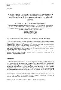
In recent years, decision diagrams have gained in importance as means for efficient representation of discrete functions in the fields of logic design and circuit testing and verification [2], [7], [12], [13], [14], [17]. Consequently, a wide variety of software packages aimed at working with decision diagrams has been developed. For example, the CUDD library is used in many applications as a standard in this area [15]. A more general extension of these methods to programming of decision diagrams for multiple-valued functions is done in [11]. Others, for example, PUMA [4] and BEMITA [13], to name but a few, support work with various particular classes of decision diagrams. More complete lists of packages and software libraries can be found in, [4], [13], [16] and references therein. More information about this subject can be found at BDD Portal [10]. In our previous work we have proposed a standard based on XML for storing and exchange of various types of decision diagrams. In this paper, we demonstrate the flexibility of the proposed system on an example of automatic generation of a graphic representation for a given decision diagram. In order to achieve this, we make use of XSLT, a language designed specifically for the purpose of conversion of data that are described using XML to other forms of representation. We have chosen this particular example for multiple reasons. Above all, it gives a clear demonstration of the concept by converting an abstract data structure into a human understandable graphical representation. In our view, this gives a good demonstration of the most important features of XML:DD framework as similar XSLT scripts can be designed for conversion to other, potentially more useful, forms of representation. The methods described in this paper can be easily adapted for other similar tasks, exporting the data to application specific formats, automatic generation of C/C++ branching code or RTL hardware descriptions in VHDL, Verilog or SystemC. The proposed framework is intended to take the position of an intermediary between various software packages aimed at working with decision diagrams. Fig. 1 illustrates the position of the XML:DD framework in wider application focused scope. In this paper, we focus, mainly, on the central part of the system, XSLT transformation engine. Second, a very important reason, is that SVG represents a pure XML derivate. The implementation of XSLT conversion scripts is therefore relatively simple and straightforward. XSLT language is primary designed for, but not limited to, conversion between various data description languages and formats derived from XML.
Figure 1: XML based framework for representation of decision diagrams. This paper is organized as follows. In Section 2 we give a quick overview of concepts needed for understanding of this paper regarding XML representation of decision diagrams, XSLT language and SVG description language for 2D vector graphic. We examine the problem of conversion of XML:DD specific entities to SVG graphic representation and present details of the implementation of XSLT scripts in Section 3. Finally, we give the conclusion in Section 4.
2
Basic Concepts
In this paper, we describe in detail the transformation process which takes a decision diagram represented in the form of an XML:DD document as an input, and converts it to a SVG graphic representation by means of XSLT style sheets. To understand the transformation process we state, first, the basics of representation of decision diagrams for switching functions using XML. We assume that the reader is already familiar with the concept of decision diagrams. For detailed information on this matter, we refer to [1]. XML is a general purpose data description language. It specifies a set of rules that a document representing particular kind of data needs to follow. XML:DD framework is a XML derivate consisting of a set of rules tailored to the task of representing decision diagrams. XML documents store data in the form of a structured text. Elements of the text form a hierarchy. In the case of XML:DD, the root element of the hierarchy is element. This element serves as a container for other elements and stores important information about the nature of the diagram, i.e., the type of the diagram and the number of levels the diagram contains. The nodes of a decision diagram are represented in the form of elements. Each node contains another sub-element corresponding to the next node in the inorder recursive traversal of the decision tree. The recursive structure of a decision diagram is thus mapped directly to the recursive properties of XML. Two separate linked lists representing parents and children nodes, elements and elements respectively, are attached to each element. A set of attributes, containing additional information about the node is associated with each node element. This set includes: 1. ID - unique identifier for each node, 2. Level in a diagram to which the node belongs, 3. Rule - An indicator of an decomposition rule applied at the node, important for many classes of decision diagrams. Used only in non-terminal nodes. 4. Constant - present only in terminal nodes, indicating the logic constant associated with the node. These elements form a complex hierarchy of interconnected data structures. In Fig. 2 we present the schematic view of this hierarchy for a binary decision diagram from the previous example.
Figure 2: XML:DD data structures. The XML:DD framework makes a heavy use of recursive properties of XML. Although this matches well the nature of decision diagrams, this organization of data is not well suited for conversion to SVG. Furthermore, some of the information stored in this way is not needed for this particular application. The SVG language is an XML derivate for description of 2D vector graphics. It is an open standard introduced and sponsored by W3 Consortium [21]. SVG conforms to the specification of general XML standard producing well-formed and valid XML documents, as specified in [19]. SVG documents can easily be processed with standard XML parsing tools or easily transformed by means of XSLT. Further information about SVG graphics format can be found in [5] and [18]. Principles of developing software systems that make use of SVG are explained in [3]. The core of the transformation mechanism described in this paper consists of a set of XSLT scripts. XSLT is an XML based language designed for specific purpose of conversion of documents in one XML based format to other data description formats. It has been introduced in 1999 in the form of the W3 Consortium recommendation [20]. The XSLT is a declarative language. It defines a style sheet, a collection of template rules, which define the relationships between entities of the source and destination XML hierarchy. The XSLT processor analyzes the source XML document, identifies the elements and transforms them according to specified template rules. New XML document is generated as an output. For details of development of XSLT style sheets we refer to [9] and [8].
3
Graphical Representation of Decision Diagrams
Although the actual visualization of the structure of decision diagrams may vary, there exists one commonly accepted way of representation accepted by most researches working in this field. By convention, non-terminal nodes of a decision diagram, are represented by circles either empty or carrying the textual label that signifies the applied decomposition rule. Terminal nodes are represented by squares or rectangles containing a logical constant. Edges are naturally represented by the lines connecting the nodes. As an option, the levels of decision diagrams can be also represented. These general principles of visualization can be easily expressed in SVG terms. In Fig. 2, we show an example of a BDD [2], for the function f (x1 , x2 , x3 ) = x1 x2 ∨ x2 x3 . The first step in the conversion from one form of representation of a decision diagram to another is to identify the correspondence between the elements of the structure of both forms. The nature of these relations will determine the set of mapping rules which are the core of the proposed conversion system. The XML:DD defines a set of entities that can be easily associated with the appropriate graphic elements. Problems in implementation arise from different constraints imposed on the two representations in question. The main focus in XML:DD is on optimal representation of greatest amount of information possible about the structure of decision diagrams. SVG deals mainly with constraints regarding spatial distribution of graphic elements. The process of automatic generation of a graphical representation for a diagram stored in the XML:DD form consists of two distinct phases: preprocessing and visualization.
3.1
Preprocessing
We begin the transformation process by applying a preprocessing XSLT script to produce a more suitable version of XML representation of a decision diagram. The preprocessing script removes recursive aspects of the XML:DD document. It will also calculate the relative coordinates of graphic elements that will form the graph representation. As the first step, the preprocessing diagram creates a wrapper element named and assign some arbitrary values for the width and height of the future SVG document. This script produces a list of decision diagram nodes, elements without any nested elements. The attributes indicating the ID, level, and expansion rule are preserved. The geometrical position of a graphic representation for each node is recalculated based on the number of nodes at each level and on the total number of levels in the diagram. These coordinates are stored in attributes of node elements in the list. Each node contains a simple list of its descendants, elements. Edges connecting the nodes will be drawn based on information from this list. The information about the parents of the node is discarded. The distinction between terminal and non-terminal nodes is marked by the value of the ’type’ attribute associated with each node element. The exact conversion process goes as follows: 1. The system takes in an XML document as an input. It locates the top level element and in the output document create a new wrapper element . 2. The XSLT script scans the hierarchy of XML elements from the document until it detects the first node element. It then evokes the appropriate ’nodes’ XSLT template which will process this element. 3. For each node element of the original document, XSLT template creates a new element in the output document. It sets the ’ID’, ’level’ and ’rule’ attributes of the new element to the values stored in the original document. Depending on the nature of the original node, it sets the value ’type’ attribute of the new element either to ’term’ or ’nonterm’ value. 4. The geometric position of the node is recalculated and coordinates are stored in appropriate attributes in the output document. 5. If the original node is non-terminal, XSLT script locates the first inside of the original node element, and evokes ’childern’ XSLT template which will create a list of outgoing edges of the node in the output document. 6. For each descendant of the original document, children template creates one element into a element in the output. The ID of the descendant is stored in the ’point’ attribute of the element. 7. Children template evokes itself again, recursively, and repeats the process for the next descendant of the original node, thus creating the next element in the list of outgoing edges in the output. 8. When the last descendant of the original node has been processed the conversion of the node is concluded, and the XSLT system proceeds to the next node in the original document again by evoking the nodes template, and so on until all the nodes in the hierarchy have been processed. To better illustrate this process we present both the original XML document containing an example of a binary decision diagram from Fig. 2, and an intermediary XML document obtained after the preprocessing.
Original XML document:
XML document after preprocessing: BDD 21 10.5 10.5 21 10.5 10.5
Notice that the original document has a distinct recursive structure while the document obtained after the preprocessing is strictly sequential. As we have stated before, the original structure reflect better the nature of decision diagrams in general. The simplified structure of the new document is, however, better suited for further processing.
3.2
Visualization
Final conversion from the intermediary XML document to a SVG document is done by a separate XSLT style sheet, which performs simple template matching replacing the elements of the XML document with an appropriate geometric representation using the precompiled coordinates stored in the intermediary XML document. This process follows the same basic lines described in the preprocessing. 1. The system takes in as an input the intermediary XML document produced in preprocessing. All valid SVG documents share the same basic structure which is repeated in every document produced by the proposed system. At the beginning of the conversion process, XSLT script identifies the element in the input document and produces a top level element of SVG document based on information on the width and the height, thus, creating a container for the rest of graphic elements that will be produced in later steps. 2. The XSLT script proceeds then to process the nodes of decision diagram starting from the root node. A separate draw node template in XSLT style sheet will be activated for every element.
SVG language describes the picture using a set of standard primitive elements. We make use of a very reduced set of these elements. Depending on the the value of ’type’ attribute this template will create either a representing a circle for a non-terminal or a representing a rectangle for a terminal node. It also produces a text element with an appropriate label for the given node. These graphic elements will be placed on the coordinates calculated by the preprocessing XSLT script. 3. In case of non-terminal nodes XSLT script creates the graphic representation of node interconnections. The information about graph edges is stored in a list of elements associated with each non-terminal node. Whenever such an element is encountered the draw edge XML template is activated. This template draws a line representing the edge or the diagram by producing element in the SVG document. Start coordinates of the line are taken directly from the attributes of the node element. the template identifies the target node using an ID stored in the ’point’ attribute of the element, and reads the end coordinates of the line from its attributes. 4. The system then continues down to the next item in the list of descendants of the current element, calling again the draw edge template. 5. Graphical elements representing the node, its label and the outgoing edges will be grouped together using the element for easier manual manipulation with other 2D vector graphics software. 6. The process is repeated for every element in the input document. Finally, we present the full code of the generated SVG document for a binary decision diagram from the previous example: BDD x1_comp x1 S x2_comp x2 S 0 x3_comp x3 S 1 x2 x2_comp S
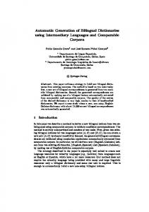
This set of XSLT style sheets produces the basic form of decision diagrams suitable for representation of various classes of diagrams including, binary, multiple valued, Kronceker or pseudo Kronecker diagrams [16]. These scripts can easily be customized both in terms of graphic properties or functionality for different applications. In Fig. 3 we give a graphic representation of a binary decision diagram for the 9sym function taken from the set of MCNC set of benchmarks for logic design, produced using the XML:DD framework.
Figure 3: Graphic representation of a binary decision diagram of 9sym benchmark function.
4
Conclusion
In this paper, we have demonstrated a method of automatic generation of graphical representation of a decision diagram stored in an XML based format. This example serves as an illustration of flexibility of XML:DD framework in conjunction with XSLT transformation language. Further XSLT based scripts can be designed for other purposes whenever some sort of correspondence between the elements of decision diagram structure and entities of the target application can be established. The method is not limited to XML based formats and can serve as a bridge to other description languages. For example, automatic generation of a hardware description in VHDL, System C or Verilog is feasible. Any software package aimed at dealing with decision diagrams capable of producing valid XML:DD documents as an output would have these features instantly at its disposal since XSLT scripts are completely platform or application independent. This permits much greater level of interoperability of different pieces of software available in this field and provides significant reduction in time needed for experimentation. We intend to explore these possibilities in our future work.
5
Acknowledgments
Authors are grateful to the Rewievers whose constructive and useful comments improved presentation in this paper. This work was supported by the Academy of Finland, Finnish Center of Excellence Programme, Grant No. 5107491.
References [1] J. Astola, R. S. Stankovi´c, Fundamentals of Switching Theory and Logic Design, Springer, 2006. [2] R. E. Bryant, “Graph-based algorithms for Boolean functions manipulation”, IEEE Trans. Comput., Vol. C-35, No. 8, 1986, 667-691. [3] K. Cagle, SVG Programming: The Graphical Web, Apress, 8 July 2002. [4] R. Drechsler, B. Becker, “OKFDDs-algorithms, applications and extensions”, in T. Sasao, M. Fujita, (ed.), Representations of Discrete Functions, Kluwer Academic Publisher, Boston, 1996, 163-190. [5] J. Eisenberg, SVG Essentials (O’Reilly XML), O’Reilly Media Inc., 5 February 2002. [6] E. R. Harold, W. S. Means, XML in a Nutshell, 2nd Edition, O’Reilly, 2002. [7] H. M. Hasan Babu, T. Sasao, “Representations of multiple-output switching functions using multiple-valued pseudo-Kronecker decision diagrams”, Proc. 30th Int. Symp. on Multiple-Valued Logic, May 23-25, 2000, 147-152. [8] S. Holzner, Inside XSLT, New Riders Publishing, 10 July 2001. [9] S. Mangano, XSLT Cookbook, O’Reilly Media Inc., December 2002. [10] Ch. Meinel, A. Wagner, “BDD Portal”, http://www.bdd-portal.org. [11] D. M. Miller, R. Drechsler, “On the construction of multiple-valued decision diagrams”, Proc. 32nd Int. Symp on Multiple-Valued Logic, Boston, Massachusetts, USA, May 15-18, 2002, 245-253. [12] S. Minato, Binary Decision Diagrams and Applictions for VLSI Synthesis, Kluwer Academic Publishers, 1996. [13] S. Nagayama, T. Sasao, “Compact representations of logic functions using heterogeneous MDDs”, Proc. 33rd International Symposium on Multiple-Valued Logic, Tokyo, Japan, May 15-18, 2003, 247-252. [14] T. Sasao, M. Fujita, (ed.), Representations of Discrete Functions, Kluwer Academic Publishers, 1996. [15] F. Somenzi, “Efficient manipulation of decision diagrams”, Int. Journal on Software Tools for Technology Transfer, 3, 2001, 171-181. [16] R. S. Stankovi´c, R.S., J. T. Astola, Spectral Interpretation of Decision Diagrams, Springer, 2003. [17] R. S. Stankovi´c, R. Drechsler, “Circuit design from Kronecker Galois field decision diagrams for multiple-valued functions”, Proc. 27th Int. Symp. on Multiple-Valued Logic, May 28-30, 275-280, 1997. [18] A. H. Watt, C Lilley, SVG Unleashed, Sams, 20 September 2002. [19] “Extensible Markup Language (XML) 1.0 (Third Edition)”, W3C Recommendation, http://www.w3.org/TR/2004/REC-xml-20040204/, 4 February 2004. [20] “XSL Transformations (XSLT) Version 1.0”, W3C Recommendation, http://www.w3.org/TR/xslt, 16 November 1999. [21] “Scalable Vector Graphics (SVG) 1.1 Specification”, W3C Recommendation, http://www.w3.org/TR/SVG11, 14 January 2003.