Abstractâ The design and implementation of digital signal processor (DSP) microprocessor-based brushless dc motor servo control driver are presented.
IEEE TRANSACTIONS ON POWER ELECTRONICS, VOL. 12, NO. 1, JANUARY 1997
53
DSP-Based Integral Variable Structure Model Following Control for Brushless DC Motor Drivers Tzuen-Lih Chern, Jerome Chang, and Geeng-Kwei Chang Abstract— The design and implementation of digital signal processor (DSP) microprocessor-based brushless dc motor servo control driver are presented. The integral variable structure model following control (IVSMFC) approach is presented to achieve robust accurate servo tracking. A design procedure is developed for determining the control function, the coefficients of the switching plane, and the integral control gain such that the error between the state of the model and the controlled plant is to be minimized. Simulation and experimental results show that the proposed approach can achieve accurate velocity/position servo tracking in the presence of load disturbance and plant parameter variations.
motion and 2) the determination of the switching function and the integral control gain such that the system has desired properties. The design, simulation, and implementation of brushless dc motor servo velocity/position control systems using the IVSMFC approach is described. The implementation of the system is based on an ADSP-2105 digital signal processor (DSP) microprocessor. Simulation and experiment results are presented for demonstrating the potential of the proposed scheme.
I. INTRODUCTION
II. SYNTHESIS OF THE INTEGRAL VARIABLE STRUCTURE MODEL FOLLOWING CONTROLLER
B
RUSHLESS dc motors have been used widely as actuators for motion control because of their higher torque/weight ratio, maintenance freedom of commutators, lower rotor moment of inertia, and better heat dissipation. The proposed scheme for a brushless dc motor velocity/position servo control system is shown in Fig. 1. The current control loop is a sinusoidal current-controlled pulse width modulated (PWM) voltage-source inverter (VSI) which is widely applied in high-performance dc drivers. The outer control loop is designed to achieve a fast and accurate servo-tracking response under load disturbance and plant parameter variations. However, such requirements are usually difficult to achieve by using a simple linear controller. In certain cases, the variable structure control (VSC) is applied [1]–[4], but it may result in a steady-state error when there is load disturbance in it. To improve this problem, the integral variable structure control (IVSC) has been proposed in [5]. The IVSC approach comprises an integral controller for achieving a zero steadystate error under step input and a VSC for enhancing the robustness. In this paper, an integral variable structure model following control (IVSMFC) approach is presented for the outer control loop. The concept of IVSMFC methodology is to apply the (IVSC) approach to the design of a model following control system (MFCS) [6], [7]. The advantage of the IVSMFC approach is that the error trajectory, in the sliding motion, can be prescribed by the design. Also, it can achieve a rather accurate servo-tracking result and is fairly robust to plant parameter variation and external disturbances. The design of an IVSMFC system involves: 1) the choice of the control function to guarantee the existence of a sliding
Let the plant be described by the following equation: (1a) (1b) and are the plant parameter, are disturbances, where and is the control input of the plant. The reference model is represented as (2a) (2b) is the input command of the system. where subtracting (2) from Defining (1), the error differential equation is (3a)
(3b) Now one applies the IVSC approach to the error dynamics in order to synthesize the control signal assuming the asymptotic convergence of the error to zero. The IVSMFC system is shown in Fig. 2 and can be described as
Manuscript received April 20, 1995; revised June 7, 1996. This work was supported by National Science Council (NSC) of Taiwan, R.O.C., under project NSC85-2213-E-110-030. The authors are with the Department of Electrical Engineering, National Sun Yat-Sen University, Kaohsiung 80424 Taiwan, R.O.C. Publisher Item Identifier S 0885-8993(97)00421-3. 0885–8993/97$10.00 1997 IEEE
(4a) (4b)
(4c)
54
IEEE TRANSACTIONS ON POWER ELECTRONICS, VOL. 12, NO. 1, JANUARY 1997
Fig. 1. Block diagram of an IVSMFC brushless dc motor velocity/position servo control system.
where the control function
is piecewise linear of the form
Substituting 7(c) into 7(b) yields
if if where
is the switching function given by (5)
constant, and is the integral control in which gain. The design of such a system involves: 1) the choice of the control function so that it gives rise to the existence of a sliding mode and 2) the determination of the switching function and the integral control gain such that the system has the desired eigenvalues.
(7d) employed to eliminate the influence due to The function and so as to guarantee the existence of a sliding mode, is constructed as (7e) where
A. Choice of the Control Function
if if
From (4) and (5), one has
if if and if if
(6)
It is known that the condition for the existence and reachability of a sliding motion is [8]–[10]
Let
(8) From (6) and (7), one can obtain where and are nominal values, and and the associated variations. be decomposed into Let the control function
are
(7a) called the equivalent control, is defined as the where solution of the problem under That is
(7b) In the sliding motion,
one can obtain (7c) (9)
CHERN et al.: DSP-BASED INTEGRAL VARIABLE STRUCTURE MODEL
55
Fig. 2. The block diagram of the IVSMFC system.
where
(11) where Thus, the conditions for satisfying the inequality in (8) are shown in (10a)–(10c) at the bottom of the page. If are chosen as
for
and
then the control function can be represented as and
(10a) for
and (10b)
and (10c)
56
IEEE TRANSACTIONS ON POWER ELECTRONICS, VOL. 12, NO. 1, JANUARY 1997
The electromagnetic torque can be expressed as
B. Determination of Switching Plane and Integral Control Gain Under ideal sliding motion, the system described by (2) can be reduced to
(15a) (12a) (12b)
where is the current constant, and is the number of poles. The torque, velocity, and position may be related by
(12c)
(15b)
The characteristic equation of the system can be represented as
(15c)
(13)
(15d)
and is independent of the plant parameters; it is robust to the plant parameter variations. It is also clear that the eigenvalues can be set arbitrarily by choosing the values of and Let the desired characteristic equation be
Then
and
can be chosen as
where is the inertia of the rotor, is a damping coefficient, is the load disturbance, and is the mechanical angular velocity of the rotor. The block diagram of a brushless dc machine, portraying (14) and (15), is shown in Fig. 3. The sinusoidal current-controlled PWM VSI as shown in Fig. 4 consists of the dc-SIN transform, current compensator, and PWM VSI circuits. The mode of the PWM VSI circuit can be simplified as a constant gain [12]
for and
III. MODELING OF BRUSHLESS DC SERVO MOTOR The brushless dc motor considered in the paper is a threephase permanent-magnet synchronous motor with sinusoidal back electromotive force (EMF). The voltage equation for the stator windings can be expressed as [11]
where is the dc supply voltage in the VSI, and are the triangular peak values. The current loop is designed to achieve fast and accurate current tracking. In this situation, the model of the current-controlled loop can be simplified to a singleinput single-output (SISO) system as shown in Fig. 5 such that the conventional methods for analyzing SISO systems may be applied with relative case. IV. AN IVSMF CONTROLLER DESIGN FOR BRUSHLESS DC MOTOR VELOCITY SERVO SYSTEM The dynamics of the brushless dc motor for velocity control can be described as (16a) (16b) where
(14)
where the applied stator voltages; the applied stator currents; the resistance of each stator winding; the inductance of the stator winding; the electrical rotor angular velocity; the electrical rotor angular displacement; the voltage constant.
and where the rotor, and
is the mechanical angular velocity of is the control input of the plant.
CHERN et al.: DSP-BASED INTEGRAL VARIABLE STRUCTURE MODEL
57
Fig. 3. Block diagram of the brushless dc motor.
Fig. 4. Block diagram of the current-controlled PWM VSI.
Fig. 5. The simplified dynamic model of a current-controlled loop.
The reference model is chosen as (17a) (17b) Defining be represented as
Following the design procedure as described in Section II, one obtains
The IVSMFC system can (18a) (18b) (18c)
(19a)
58
IEEE TRANSACTIONS ON POWER ELECTRONICS, VOL. 12, NO. 1, JANUARY 1997
Defining can be represented as
where Sup
The IVSMFC system
(24a) (24b) (24c)
(19b) Sup
(19c)
and Sup The
(19d) (24d)
function, constructed from (5), is
Following the design procedure as described in Section II, one obtains In the sliding motion, the system described by (18) can be reduced to the following simple linear form: (20a) (20b) The characteristic equation of this reduced system is
Let and be the desired eigenvalues. Then be chosen as
and
(25a)
can where (21a) (21b)
(25b)
V. AN IVSMF CONTROLLER DESIGN FOR BRUSHLESS DC MOTOR POSITION SERVO SYSTEM
(25c) (25d)
The dynamics of the brushless dc motor for position control can be described as (22a) (22b) (22c)
and (25e) The
function, constructed from (5), is
where In the sliding motion, the system described by (24) can be reduced to the following simple linear form: (26a) (26b) The characteristic equation of this reduced system is
and where is the mechanical angular angle of the rotor, and is the control input of the plant. The reference model is chosen as (23a) (23b) (23c)
Let and
and be the desired eigenvalues. Then can be chosen as (27a) (27b) (27c)
CHERN et al.: DSP-BASED INTEGRAL VARIABLE STRUCTURE MODEL
59
Fig. 6. The configuration of the prototype brushless dc motor driver.
VI. EXPERIMENTAL SYSTEM SETUP To verify the performance of a proposed scheme, a prototype implementation of the brushless dc motor driver as shown in Fig. 6 consists of a power amplifier stage and control stage. The power amplifier stage includes a PWM and delay circuit, power driver circuit, power MOSFET circuit, and current detect circuit. The control stage is based on an ADSP2105 microprocessor which is a 16-b fixed point 10-MHz DSP chip. It can perform all neccessary controls such as the position, speed, acceleration and IVSMFC e.t.a. The 12-b DAC, 12b ADC, and 16-b decoder circuits are necessary for data translation. The executive file is downloaded from the PC to the DSP through an RS-232 link. The sampling period using in this scheme is 67 s.
VII. SIMULATION AND EXPERIMENTAL RESULTS OF BRUSHLESS DC MOTOR VELOCITY SERVO DRIVER
THE
The robustness of the proposed IVSMFC approach against large variations of plant parameters and external load disturbances has been simulated for demonstration. The nominal values of parameters used in this scheme are listed in Table I. Choosing the poles of the reference model (17) at 30 and 50, one can obtain
From the poles of the system (20) at from (21), one can obtain
40 and
60,
60
IEEE TRANSACTIONS ON POWER ELECTRONICS, VOL. 12, NO. 1, JANUARY 1997
TABLE I SYSTEM PARAMETERS
(a)
By considering operating points, one assumes the range of the plant parameter variations to be
(b)
Thus, from (19), the gain the following inequalities:
must be chosen to satisfy
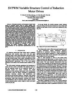
Fig. 7. Simulation responses of the brushless dc motor driver (!c = 100 rad/s). (a) The response of the angular velocity !m of the rotor and (b) the velocity error state e1 of the model and the rotor.
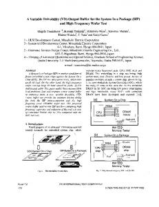
And, based on simulations, one possible set of the switching gains can be chosen as The simulation results of the dynamic response are plotted in Figs. 7–9. Fig. 7 shows the rotor angular velocity response and its velocity error state between the model and rotor. Figs. 8 and 9 show the velocity responses under the presence of sinusoidal load t N-m) at time 0.5 s and variations of plant and , respectively. Obviously, the IVSMFC parameters approach is insensitive to the variation of the plant parameters and the load disturbance. Fig. 10 shows the experimental waveforms of the brushless dc motor drive for a step change of velocity command. The dynamic characteristic indicates fast and accurate responses. Fig. 11 shows the experimental responses of angular velocity and phase current by putting a step constant load (1.5 N-m). It also shows the robustness to the load disturbance. VIII. SIMULATION AND EXPERIMENTAL RESULTS OF BRUSHLESS DC MOTOR POSITION SERVO DRIVER
Fig. 8. Simulation responses of velocity with different kind of load placed at time 0. 5 s with sinusoidal load (T l = 0:1 sin 8�t N-m; !c = 100 rad/s).
From the poles of the system (26) at ( 60, 60), from (27), one can obtain
60,
The gains and must be chosen to satisfy (25), and based on simulations, one possible set of the switching gains can be chosen as
THE
Choosing the poles of the reference model (23) at one can obtain
and
The simulation and experimental results of the dynamic response are plotted in Figs. 12–16. Fig. 12 shows the rotor angular position response and its position error state between
CHERN et al.: DSP-BASED INTEGRAL VARIABLE STRUCTURE MODEL
61
(a)
= 100
Fig. 9. Simulation of velocity response (!c rad/s) with IVSMFC approach under random deviations of Jm from 0–300% and Bm from 0 to 0.01.
+
(b) Fig. 11. Experimental results by putting a step constant load at an instant time (T l : N-m, !c rad/s). (a) Variation of angular velocity response and (b) response of phase current ias :
= 15
= 50
(a)
(a) (b)
(c)
= 100
Fig. 10. Experimental result of the brushless dc motor driver (!c rad/s). (a) The response of the angular velocity !m of the rotor, (b) the response of the control function Up ; and (c) the response of the phase current ias :
the model and rotor. Figs. 13–14 show the motor position control system owns robust response under a different type of load such as constant (0.4 N-m) and sinusoidal load ( N-m); it is robust to the variation of motor parameters and
(b)
=3
rad). Fig. 12. Simulation responses of the brushless dc motor driver (�c (a) The response of the position �m of the rotor and (b) the position error state e1 of the model and the rotor.
Experimental results shown in Figs. 15 and 16 behavior the fast and robust response even in both placing and removing load at an instant time. The results of the experiment also match those of simulations. From the observations, it is obvious that the proposed approach can achieve accurate and robust responses.
62
IEEE TRANSACTIONS ON POWER ELECTRONICS, VOL. 12, NO. 1, JANUARY 1997
(a) (a)
(b)
=3
Fig. 15. Experimental result of the brushless dc motor driver (�c rad). (a) The response of the position �m of the rotor and (b) the response of the control function Up : (b) Fig. 13. Simulation results with placing and removing load (0.4 N-m) at time 0.6 and 1.4 s, respectively. (a) Position response of rotor �m and (b) position error response e1 :
(a)
(a)
(b)
=04
: N-m). (a) Fig. 16. Experimental results by putting and lifting load (T l The position �m when putting load and (b) the position �m when removing load at a certain instant.
IX. CONCLUSION
(b) Fig. 14. Simulation of position response with sinusoidal load and random deviation in motor parameters (�c rad). (a) The response of rotor position �m with sinusoidal load ( : �t N-m) at time 0.5 s. (b) The position response with an IVSMFC approach under random deviation of Jm from 0–300% and Bm from 0 to 0.05.
=3 0 1 sin 8 +
This paper presents an IVSMFC configuration and develops a procedure for determining the control function and switching plane. It has been shown that the proposed approach is theoretically robust to the plant parameter variations. A DSP-based brushless dc motor velocity/position servo control driver is presented for demonstrating the potential of the IVSMFC approach. Simulation and experimental results show that the proposed approach can achieve accurate and fast
CHERN et al.: DSP-BASED INTEGRAL VARIABLE STRUCTURE MODEL
velocity/position servo tracking in the face of large parameter variations and external disturbances. It is a considerably robust and practical control law for a servomechanism system. REFERENCES [1] C. Rossi and A. Tonielli, “Robust control of permanent magnet motor: VSS techniques lead to simple hardware implementations,” IEEE Trans. Ind. Electron., vol. 41, pp. 451–460, 1994. [2] K. W. Lim, T. S. Low, M. F. Rahman, and L. B. Wee, “A discrete time variable structure controller for a brushless dc motor drive,” IEEE Trans. Ind. Electron., vol. 38, pp. 102–107, 1991. [3] J. P. Karunadasa and A. C. Renfrew, “Design and implementation of microprocessor based sliding mode controller for brushless servomotor,” Proc. Inst. Elect. Eng., vol. 137, pt. B., pp. 345–363, 1991. [4] T. S. Low, K. J. Tseng, T. H. Lee, K. W. Lim, and K. S. Lock, “Strategy for the instantaneous torque control of permanent magnet brushless dc drivers,” Proc. Inst. Elect. Eng., vol. 138, no. 6, pt. B., pp. 355–363, 1990. [5] T. L. Chern and Y. C. Wu, “Design of integral variable structure controller and application to electrohydraulic velocity servo systems,” Proc. Inst. Elect. Eng., vol. 138, pt. D., pp. 439–444, 1991. [6] K. D. Young, “Asymptotic stability of model reference systems with variable structure control,” IEEE Trans. Automat. Contr., vol. AC-22, pp. 279–281, 1977. , “Design of variable structure model following control systems,” [7] IEEE Trans. Automat. Contr., vol. AC-22, pp. 1079–1085, 1978. [8] V. I. Utkin, “Variable structure systems with sliding modes,” IEEE Trans. Automat. Contr., vol. AC-22, pp. 212–222, 1977. [9] U. Itkis, Control Systems of Variable Structure. New York: Wiley, 1976. [10] V. I. Utkin, Sliding Modes and Their Application in Variable Structure Systems. Moscow, Russia, 1978. [11] P. C. Krause and O. Wasynczuk, Electromechanical Motion Devices. New York: McGraw-Hill, 1989. [12] D. M. Brod and D. W. Novotny, “Current control of VSI-PWM inverters,” IEEE Trans. Ind. Applicat., vol. IA-21, pp. 562–570, 1985.
Tzuen-Lih Chern was born in Kaohsiung, Taiwan, R.O.C., in 1958. He received the M.S. degree in 1985 and the Ph.D. degree in 1992, both from the Institute of Electronics, National Chiao Tung University, Taiwan. From August 1987 to January 1992, he was a Lecturer at the Department of Electrical Engineering, National Sun Yat-Sen University, Taiwan. He has been an Associate Professor since February 1992. His research interests include variable structure control, ac motor drivers, and microprocessor-based control systems.
63
Jerome Chang was born in Kaohsiung, Taiwan, R.O.C., on January 21, 1952. He received the B.S. and M.S. degrees from the Chung Cheng Institute of Technology, Taoyuang, Taiwan, in 1975 and 1981, respectively. He is currently working toward the Ph.D. degree from the Institute of Electrical Engineering at National Sun Yat-Sen University. His research areas are variable structure and motor drivers. He has worked in the 205th Arsenal of the Combined Services Forces of the Republic of China in instrument control, measurement control, quality control, and manufacturing process automation. Mr. Chang is a Member of the Chinese Institute of Engineers and a Certified Engineer of Chinese Society for Quality Control.
Geeng-Kwei Chang was born in Chiayi, Taiwan, R.O.C., on June 30, 1970. He received the B.S. degree from National Cheng-Kung University, Taiwan, in 1993 and the M.S. degree from the Institute of Electrical Engineering at National Sun Yat-Sen University, in 1995. He is currently working towards the Ph.D. degree at the Institute of Electrical Engineering. He is engaged in research of variable structure control and brushless dc motor drivers.