depends on the translational velocity and yaw rate of the vehicle, which ... using extra optical flow sensors, output feedback method is also adopted as an ...
Dynamic Output Feedback Image-based Visual Servoing of Rotorcraft UAVs Hui Xie∗ , Jianan Li†‡ , and K.H. Low† ∗ Air
Traffic Management Research Institute, Nanyang Technological University, Singapore 639798 of Mechanical and Aerospace Engineering, Nanyang Technological University, Singapore 639798 ‡ Department of Mechanical Engineering, Technische Universit¨at M¨ unchen, Germany 80333
† School
Abstract—This paper presents an improved dynamic output feedback image-based visual servoing (IBVS) law for a quadrotor in comparison with our previous work (“Dynamic Visual Servoing of a Rotary-wing Unmanned Aerial Vehicle Without Velocity Measurement,” in AIAA Guidance, Navigation, and Control Conference, Grapevine, Texas, January, 2017). The controller enables the quadrotor to regulate its position and yaw relative to a planar target consisting of multiple points. This new IBVS controller removes the integral term used to counter external disturbance, in which way the controller’s structure is further simplified. Same as in our previous work, the controller requires a minimum set of sensors, i.e., an inertial measurement unit and a single downward facing camera. Also, this approach is adaptive to various unknown system parameters, such as thrust coefficient, mass of the vehicle, and bias errors in Euler angle measurement. The asymptotic stability of error dynamics is proven. Both simulation and experimental results are presented to demonstrate the performance of the proposed controller.
I. I NTRODUCTION In the applications of rotorcraft UAVs, one common task is to control the UAV’s position and attitude relative to a target. The easy-to-access GPS signals provide one solution to the task. However, in the situation where GPS signals are not available, such as in indoor condition, another solution shall be came up with. One alternative is to use a camera providing visual information to assist controlling the vehicle. In a closed-loop system where visual information is integrated as feedback, it is referred to as visual servoing [1]. Visual servoing laws are usually categorized into position-based visual servoing (PBVS) law and image-based visual servoing (IBVS) law [1]. IBVS law is usually considered easier to be implemented since it does not require a prior 3-D model of the target and pose reconstruction which requires more precise camera calibration [2]. Thus, this paper focuses on IBVS law. For systems like quadrotors doing high speed tasks and are underactuated, their dynamics need be considered when designing visual servoing laws. The IBVS law considering a system’s dynamics is named as dynamic IBVS [3]. In the design of dynamic IBVS laws, the first challenge is that the nonlinear perspective projection of the camera will destroy the passivity property of the vehicle’s dynamics [3]. To address this issue, the virtual camera approach is adopted due to its simplicity and decoupled structure [3]. This approach defines a virtual camera which has the same
position and yaw angle as the real camera’s but constant roll and pitch angles. The image features are defined in virtual image plane. Therefore, the resulting image kinematics only depends on the translational velocity and yaw rate of the vehicle, which recovers the passivity property. Existing works usually assume that the velocity information of the vehicle is generally obtained from GPS or derived from optical flow. For example, paper [4] and [5] use optical flow to estimate the scaled linear velocity with the spherical image moment features as in [6]. Work in [7] combines attitude measurement obtained from inertial measurement unit (IMU) and spherical optical flow to estimate the scaled translational velocity of the UAV in inertial frame. A nonlinear adaptive trajectory tracking controller is then designed to enable the UAV to land on a ship deck, which ensures the global asymptotic stability of the system. Besides using extra optical flow sensors, output feedback method is also adopted as an alternative. In work [8] and [9], the authors use spherical moment features and an observer to calculate the translational velocity of the UAV. The desired value of depth is used as a nominal value for actual depth appearing in the observer. Both simulation and experimental results show the robustness of the observer to the unknown depth value. This work requires desired depth information as shown above but does not give a rigorous robustness analysis for choosing the desired depth value. Work in [10] uses spherical image moment features and output feedback method in the design of IBVS laws. Similar work is done in [11] where the authors use a set of first-order image moment features of points in a virtual camera and then propose an output feedback controller. It is further extended that the UAV is able to track a moving target in [12]. In [13] an UAV is also enabled to track a moving target using a virtual camera and an adaptive output feedback controller. Works in [10]–[13] prove global asymptotic stability of the system theoretically but they are not experimentally validated, which is probably because of the resulting complicated controller structure. Recently in [14] a dynamic output feedback image-based visual servoing law for UAVs is proposed to adapt various system uncertainties, such as thrust constant and attitude bias which have been experimentally shown in [3], [15] to the motion accuracy of the vehicle if not being compensated. In [14] only simulation results are provided to show the
performance of the proposed controller. This paper further extends the work in paper [14]. The first contribution of this paper is that it removes the integral term for estimating the effect constant disturbance in the observer design while the proposed controller is still robust to disturbances, which originate from system uncertainties. Another contribution of this work is that the controller is experimentally evaluated, which should be compared to the works in [10]–[14] where only simulation results are given. This paper is structured as follows. Section II describes reference coordinate frames, dynamics of the quadrotor, a vector of image features and its kinematics. Section III presents the details of the adaptive output feedback IBVS controller and stability proof. Simulation and experimental results are given in Section IV and Section V. Finally, Section Sensors VI concludes the paper.
f2 II. DYNAMIC IBVS M ODELING f3 ¿
¿
2
3
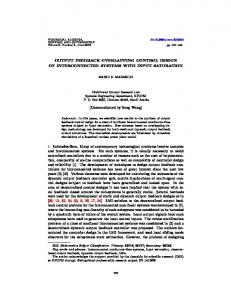
c ` f4 Three coordinate frames are used in describing the IBVS f1 c 1. In this paper, ¿ model as shown¿ in Fig. the target is assumed 1
2
4
1
c
3
real camera C
V
virtual camera
tvnc
feature point
N
Fig. 1. Frame definition. Although the frame V and N share the same origin, to clearly show the idea of virtual camera the two frames are plotted with an offset.
to be a set of coplanar points on the ground. Thus, the first frame is navigational frame N with its origin at the target’s plane and the third basis n3 pointing downward. The second frame is the virtual camera frame V whose origin is at the optical center of the camera but has zero roll and pitch angles, which means the virtual image plane is always parallel to the target plane. The third frame is the real camera frame C with its origin at the optical center and fixed on the rotorcraft. To transform among the three coordinates, a normalized Euler angle-based rotation matrix can be applied. The definition of image moment features is the same as in [14], which is denoted as s = [sTl , sh , sφ ]T . Combined with the quadrotor’s dynamics, the whole IBVS dynamic model
can then be summarized as the following: λvl − Gsl ψ˙ Z v∗ v3v s˙ 3 = − v∗ Z s˙ 4 = −ψ˙ s˙ l = −
(1a) (1b) (1c)
˙ 3 )v v + gE3 + v˙ v = −S(ψE
v
F m
R˙ = RS(ω c ) c
ω˙ = −J
−1
(1d) (1e)
c
c
S(ω )Jω + J
−1 c
τ
(1f)
where the first three equations describe the kinematics of the image moment features and the latter three equations represent the dynamics of the quadrotor, the linear velocity expressed in V is v v = [vlT , v3v ]T = [v1v , v2v , v3v ]T and ω c is the angular velocity of the camera in C, λ is the focal length of the camera, Z v∗ is the desired depth value of the target plane in V, g is the gravity constant, m is the mass of the vehicle and J is the inertia of the vehicle, G and E3 are� two constant matrix which are E3 = [0, 0, 1]T � 0 −1 and G = , the transformation matrix between N 1 0 and V is denoted as R and parameterized by Euler angles η = [φ, θ, ψ], the map S(·) : R3 7→ R3×3 yields a skew symmetric matrix that verifies S(x)y = x × y, for x and y ∈ R3 , the force in frame V is F v = −Rθφ E3 TM , TM is the sum of thrust generated by four propellers P4 ˜and 2 it is approximated as TM = KT uh = KT i=1 W i , 2 ˜ Wi = Wi − Wmin , Wi is the PWM signal fed into the ESC driving ith propeller, Wmin is the minimum pulse width to start the propeller and KT is the thrust constant, τ c is the moment generated by propellers. Same as in [3], [14], [15], a cascade control structure is adopted, where the outer IBVS loop regulates the image feature errors and the inner loop tracks the reference attitude receiving from the outer IBVS controller. The inner loop takes the PID controller and is assumed to have large enough bandwidth to ensure the stability of the whole closed-loop system. To avoid the target leaving the camera’s field of view (FoV) [3], [16], IBVS control requires that the reference rollpitch angles are limited to a small range. Therefore, a small angle approximation can be made [3], [15] and F v becomes −θm + θe F v ≈ KT uh φm − φe (2) −1 where φe and θe denote the slowly time-varying bias errors in the Euler angle estimates from an attitude and heading reference system (AHRS), φm and θm are measured roll and pitch angles. The bias errors φe and θe will be treated as additive input disturbances to the outer-loop and compensated by the method of adaptive control. The thrust constant will be treated as an unknown constant parameter since it will slowly decrease as the battery voltage drops during a flight, as indicated in [15]. More details of modeling, two-loop control structure, and system uncertainties can be found in [3], [14], [15].
III. O UTER - LOOP DYNAMIC IBVS C ONTROL A. Height, Lateral Subsystems and Generalization From (1b), (1d), and (2), the height subsystem can be separated out and written as v3v Z v∗ � � K mg T v v˙ 3 = − uh m KT s˙ 3 = −
yξ = Cξ
(3b)
(5a) (5b)
T
where ξ = [ξ1 , ξ2 ] ∈ R2 , ξ1 represents s3 − 1 in (3) or si , i = 1, 2 in (4), ξ2 denotes v3v /Z v∗ in (3) or λviv /Z v∗ , i = 1, 2 in (4), yξ is the output variable, b and d are unknown constants dependent on KT , m, θe , and φe , u is equivalent to the term ul in (3) or θm , φm in (4), and � � � � � � 0 −1 0 A0 = , B= , C= 1 0 0 0 1 B. Control Law Development In this subsection, the design details of the adaptive output feedback dynamic IBVS controller is provided. For a quantity ˆ is the estimation ξ, its estimate is expressed as ξˆ and ξ˜ = ξ−ξ error. The estimate of ξ can be designed as ξˆ = ξˆy + bξˆu T
(6) T
where ξˆy = [ξˆy1 , ξˆy2 ] , ξˆu = [ξˆu1 , ξˆu2 ] , and is updated by � � ˙ ξˆy = Ao ξˆy − LC ξˆy − ξ (7a) ˙ ξˆu = Ao ξˆu − LC ξˆu + Bu
˙ ξ˜ = Acl (ξ˜ − H)
(3a)
where uh is the input of the subsystem in (3). The objective for the height subsystem is to regulate the image feature error es3 = s3 − 1 to be zero because the image feature s3 becomes s3 = 1 when the UAV hovers at the desired height. In this paper, the yaw rate is assumed to be zero, i.e., ψ˙ = 0 because yaw rate does not effect the translational velocity of the vehicle. We remark that this assumption is not restrictive as the yaw rate can be easily stabilized. With the assumption above and using (1a) and (1d), the lateral subsystem can be written as λv v (4a) s˙ i = − v∗i , i = 1, 2 Z KT uh v˙ 1v = (θe − θm ) (4b) m KT uh (φm − φe ) (4c) v˙ 2v = m As the image feature error s3 tends to 1, another assumption could be made that uh = u∗h because the variation of uh is relatively small. u∗h is the constant input enabling the quadrotor to hover at the desired height. Then the height subsystem and lateral subsystem can be uniformly written as ξ˙ = A0 ξ + bB (u − d)
countering constant disturbance is removed in the observer design. However, the controller is still proven to be able to stabilize the system. From (5a), (6), and (7), we can easily prove
(7b)
T where ξ˜ = [ξ˜1 , ξ˜2 ] , Acl = Ao − LC and H = [H1 , H2 ]T = bd[−1/l1 , l1 /l2 ]T .We remark that although the estimation error signal (ξ˜ − H) exponentially converges to zero, (6) cannot be used to provide a state estimate as it depends on unknown constants b and d. This type of observer is termed as implicit observer in [10] [14]. The control law is summarized in the following theorem with proof.
Theorem 1. The origin of the system described in (5) with filters in (7), the adaptive output feedback control law u = −l2 ξˆu1 + sgn (b) γ1 δ1 w1T w1 + ϑˆT1 q � � T 2 − k2 + d2 (k1 + d1 ) ϑˆ211 δ2 − ϑˆ2 w2 ˙ ϑˆ1 = sgn (b) γ1 δ1 w1 ˙ ϑˆ2 = γ2 δ2 w2
(9) (10) (11)
where δ1 = ξ1
(12) T
w1 = [(k1 + d1 )δ1 − ξˆy2 , l1 /l2 ] � � T q = [−(k1 + d1 )ξˆy2 − l2 ξˆy1 − ξ1 , 0]
(13) (14)
δ2 = ξˆu2 − ϑˆT1 w1 (15) T ˆ ˆ ˆ w2 = [ϑ11 (k1 + d1 )ξu2 − δ1 , −ϑ11 (k1 + d1 )l1 /l2 ] (16) 1, x > 0 −1, x < 0 (17) sgn (x) = 0, x = 0 is globally asymptotically stable. ki , di , γi , i = 1, 2 are positive control gains and variables ϑˆ1 , ϑˆ2 are the estimates T T of variables ϑ1 = [ 1b , d] , ϑ2 = [b, bd] respectively, Proof. The control law is derived using Lyapunov theory and backstepping technique. The first error variable is defined as the image feature error δ1 which is given in (12). Combined with (5a), (6), and (7), the derivative of the first error δ1 becomes δ˙1 = −ξˆy2 − bξˆu2 + ξ˜2 (18) In (18), we note that only the time derivative of variable ξˆu2 contains the control input u. Therefore, the variable ξˆu2 is chosen as the virtual control input in the backstepping procedure. Combined with the definition of δ2 in (15), the expression of δ˙1 can also be written as δ˙1 = −(k1 + d1 )δ1 − bδ2 − bϑ˜T1 w1 + (ξ˜2 − H2 )
(19)
The first Lyapunov function is selected as
T
where L = [l1 , −l2 ] , li , i = 1, 2 is a positive constant. Note that the integration term in [14] which is used for
(8)
V1 =
1 2 |b| ˜T ˜ 1 δ + ϑ ϑ1 + (ξ˜ − H)T Pcl (ξ˜ − H) 2 1 2γ1 1 d1
(20)
V˙ 1 = − (k1 + d1 )δ12 − bδ1 δ2 + δ1 (ξ˜2 − H2 ) 1 − (ξ˜ − H)T (ξ˜ − H) d1
(21)
Using the definition of w1 in (13) combined with updating law in (7a), (7b) and (18), we get the time derivative of w1 as �# " � −b(k1 + d1 ) ξˆu2 − dll21 w˙ 1 =q + 0 � � ˜ (k1 + d1 )(ξ2 − H2 ) + (22) 0 The time derivative of the second error δ2 is obtained by using (7b), (10) and (22), δ˙2 =l2 ξˆu1 + u − sgn (b) γ1 δ1 w1T w1 − ϑˆT1 q + ϑT2 w2 + bδ1 − ϑˆ11 (k1 + d1 )(ξ˜2 − H2 ) (23) We choose the second Lyapunov function as
T
image feature error is denoted as es = [es1 , es2 , es3 , es4 ] = s−s∗ , where the desired value is s∗ = [0, 0, 1, 0] corresponding to four image features. The desired 3-D translational T displacement of the vehicle is tn∗ nc = [0.053, −0.052, −1.50] m which corresponds to the value when es = 0. The desired value of the depth is Z v∗ = 1.0 m. The vehicle is initially T placed at tnnc (0) = [0.2, −0.2, −1.0] m in the navigation frame. It has zero roll and pitch angles but π/6 rad in yaw angle. The initial velocities are set as v v (0) = 0 m/s and ω c (0) = 0 rad/s. The roll and pitch bias error is T ηe1 = [0.0349, 0.0349] rad. The visual target consists of T two coplanar points located at coordinates [−0.18, 0, 0] m T and [0.18, 0, 0] m in N . The control parameters for height subsystem in (3) are given in Table I. Due to the symmetry of quadrotor, the chosen control parameters for two lateral subsystems are the same and their values are shown in Table II. The control law for regulating the feature s4 to TABLE I G AINS FOR HEIGHT SUBSYSTEM IN SIMULATION Parameter Value
1 ˜T ˜ 1 1 ϑ2 ϑ2 + (ξ˜ − H)T Pcl (ξ˜ − H) V2 = V1 + δ22 + 2 2γ2 d2 (24)
V˙ 2 = − k1 δ12 − k2 δ22 − d1 δ12 + δ1 (ξ2 − H2 ) − d2 (k1 + d2 )2 ϑˆ11 δ 2 − (k1 + d1 )ϑˆ11 (ξ2 − H2 )δ2 2
−(
1 1 + )(ξ˜ − H)T (ξ˜ − H) d1 d2
Finally, using the inequality 2xy 6 x2 + y 2 , we can show that 3 1 1 V˙ 2 6 −k1 δ22 − k2 δ22 − ( + )(ξ˜ − H)T (ξ˜ − H) 4 d1 d2 Using the LaSalle-Yoshizawa Theorem in [17] we can show ˜ δi , ϑˆi , i = 1, 2, and the convergence the boundedness of ξ, ˆ of ϑi , δi , i = 1, 2 to zero. With the definition of ξˆy and the boundedness of ξ˜1 , we can prove that the values of ξˆy are bounded. Similarly, using the definition of ξˆ1 = ξˆy1 + bξˆu1 , and the boundedness of ξ˜1 and δ1 , we can conclude the boundedness of ξˆ1 and ξˆu1 . Also the definition of w1 and δ2 , and the boundedness of δ2 , ξˆy2 , imply the variables w1 and ξˆu2 are bounded. Finally, with the boundedness of variables shown above and the proposed control law in (9), we can conclude the input u for system in (5) is bounded.
d1 0.01
Parameter Value
k1 2.0
d1 0.01
d2 0.1
γ1 1
γ2 1
l1 12
l2 36
k2 20
d2 0.1
γ1 0.1
γ2 0.1
l1 10
l2 25
zero is a proportional control which is the same as the law in [3], [15], [16]. Same as in work [3], [16], [18], a PID controller is adopted for the inner attitude loop. Fig. 2 shows the time evolution of es , et = T ∗ [et1 , et2 , et3 ] = tnnc − tn∗ nc , and eψ = ψ − ψ . We can see that the image feature errors es and position errors et asymptotically converge to zero. This result proves that the proposed controller is able to eliminate the steady state error resulting from attitude bias, which is not considered in existing output feedback based IBVS laws [10], [11], [13]. We also observe that the yaw motion is nonzero in the transient period and exponentially converges to zero. This observation shows that the proposed approach still works if the disturbance resulting from yaw motion is exponentially vanishing. 0.5
1 0.5
0 es1 (mm) es2 (mm) es3 es4 (rad)
-0.5
IV. S IMULATION R ESULTS The proposed controller is tested in Matlab simulation before the experiment. The physical constants are as the following: the vehicle’s mass m = 1.6 kg, inertia J = diag([0.03, 0.03, 0.05]) kg·m2 , torque constant KT = 20 N·ms2 , focal length λ = 2.8 mm, image sensor size 3.2 mm×2.4 mm with the resolution of 320 × 200 pixels. The
k2 10
TABLE II G AINS FOR LATERAL SUBSYSTEM IN SIMULATION
es
Employing (11), (21) and (23), the time derivative of V2 can be derived as
k1 0.5
et , eA
where Pcl satisfies Pcl Acl + ATcl Pcl = −I2 , I2 ∈ R2×2 is an identity matrix. Employing (10) and (19), the time derivative of V1 is
0
e t1 e t2 e t3 eA
-0.5
-1
(m) (m) (m) (rad)
-1 0
10
time (sec)
20
0
10
20
time (sec)
Fig. 2. Time evolution of image moment feature errors es and et
Fig. 3 illustrates the time evolution of reference roll and pitch of the quadrotor for the inner attitude loop. Fig. 4
150
1) Pixhawk Autopilot: A 3D accelerometer, a 3D gyroscope and a 3D magnetometer are already embedded in the autopilot. To estimate attitude and angular velocity of the vehicle, an extended Kalman filter-based AHRS is adopted to fuse the IMU and magnetometer sensor data. The Pixhawk autopilot generates the reference PWM signals and feeds into four ESCs. The ESCs then drive the four 840 RMP/V brushless motors mounted with 10 × 3.800 multi-rotor propellers. 2) Pixy Camera: The Pixy camera is mounted at the bottom and close to the center of gravity of the quadrotor. It has a focal length of λ = 2.8 mm. The lens on the camera has 75◦ horizontal and 47◦ vertical field of view. The image sensor size of the camera is 1/400 . The camera module transmits image point coordinates at a rate of 25 Hz with a resolution of 320 × 200 pixels. The total weight of the vehicle including batteries and a computer vision system is around 1.6 kg. The arm length of the frame is l = 0.2 m. The vehicle is powered by two 11.1V 2200 mAh LiPo rechargeable batteries. For other physical constants, image feature error notations and initial states of the vehicle, please refer to the section IV.
100
B. Experimental Results
attitude reference (rad)
0.2 reference roll reference pitch
0.1
0
-0.1 0
5
10
15
20
time (sec) Fig. 3. Time evolution of roll and pitch reference.
shows the image trajectories of two target points. It can be
200
In this experiment, the visual target are two coplanar points on the ground and separated by around 0.36 m. The control gains of the outer-loop are shown in Table III and Table IV.
50
0 0
50
100
150
200
250
300
Fig. 4. Image trajectories of two target points. The symbols ∗ and ◦ represent the starting and end points, respectively. The rectangle shows the boundary of the image sensor.
seen that the visual target stays in the camera’s FoV. We remark that although the Theorem 1 guarantees the stability of the closed-loop system for any positive control gains, to practically implement the proposed IBVS law requires tuning control gains appropriately to obtain satisfactorily transient trajectories. Otherwise, the visual target will potentially leave the camera’s FoV during the transient period, which fails the visual servoing task.
TABLE III G AINS FOR HEIGHT SUBSYSTEM IN EXPERIMENT Parameter Value
k1 0.5
d1 0.01
k2 5
d2 0.01
γ1 0.05
γ2 0.1
l1 4
l2 4
TABLE IV G AINS FOR LATERAL SUBSYSTEM IN EXPERIMENT Parameter Value
k1 2
d1 0.01
k2 10
d2 0.01
γ1 0.1
γ2 0.1
l1 7.2
l2 9
Fig. 6 illustrates the time evolution of image moment feature errors and Fig. 7 shows the position and yaw errors. It
es2 (mm) 0
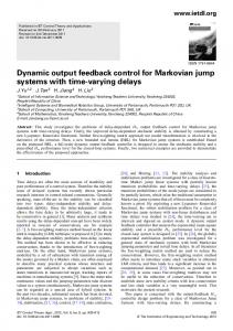
es 3
As shown in Fig. 5, The quadrotor is equipped with a CMUcam5 Pixy on-board computer vision system [19] and a open-source Pixhawk autopilot [20].
0.1 0 -0.1
0.6 0.4 0.2 0 0
0.6 0.4 0.2 0 -0.2
20 40 time (sec)
es4 (mm)
A. Experimental Platform
es1 (mm)
V. E XPERIMENTAL E VALUATION
20 40 time (sec)
0
20 40 time (sec)
0
20 40 time (sec)
0.05 0 -0.05 -0.1
Fig. 6. Time evolution of image moment feature errors es Fig. 5. The built quadrotor UAV.
can be seen that these error signals reach the steady state
0
0
20 40 time (sec)
0.1 0.05 0
0
#10-3
0 -2
20 40 time (sec)
20 40 time (sec)
0
20 40 time (sec)
Fig. 8. Time evolution of height subsystem estimates
ϑl11 , ϑl21 , ϑl22 , ϑl23 are increasing. This is because the right sides of expressions (10) and (11) contain terms of square of error signals. Due to existing noise the error signals can not be zero exactly, the value of estimate of ϑi will continuously increase. This issue can be addressed by adding a projection operator [21] without changing the stability of the closedloop. The time evolution of outer-loop inputs is shown in Fig. 10. It can be seen that after about 35 seconds, the values of φm and θm become larger. This is due to the growing value of ϑi , which correspondingly increase the control gains in (9). The large gains usually increase the sensitivity of the closedloop to system noise. This can be solved by bounding the value of estimate ϑi through the projection operator. Fig. 11 shows the trajectory of image points in the field of view and Fig. 12 shows the trajectory of the quadrotor. Symbol “∗“ means the starting point and symbol “◦“ means the ending point of the vehicle. As one can see, the vehicle starts from a height around 1.5 m and a certain distance from the origin
#l21 #l22
0
0.02
5
0 -0.02
20 40 time (sec)
#10
-5
0 -5
0
20 40 time (sec)
0
20 40 time (sec)
?m (rad)
Fig. 9. Time evolution of lateral subsystem estimates
0.06 0.04 0.02 0 -0.02 0
20 time (sec)
40
0
20 time (sec)
40
0
20 time (sec)
40
0.04 0.02 0 -0.02
-0.01 -0.02
0
#10 -5
-5
0
#h22
#h21
2
20 40 time (sec)
20 40 time (sec)
0
20 40 time (sec)
uh (ms)
0
0
3m (rad)
#h12
#h11
-0.1
0 -0.02 -0.04
5
0
#l13
after around 20 seconds. Through the vertical axis of Fig. 6 and 7, it can be seen that these oscillations are within very small range. For image moment feature errors, the oscillation magnitude are within 0.2 for es1 and es2 , and 0.2 for es3 . For position and yaw angle errors, the oscillation range is within 0.1 m and 0.1 rad respectively. Fig. 8 and 9 illustrate the trajectory of estimated parameters for height and lateral subsystems respectively. We can observe that the estimates of
0
0
-0.05
20 40 time (sec)
0
20 40 time (sec)
0.05
0
#10 -3
-1 0
Fig. 7. Time evolution of position and yaw errors et
-0.05
1
0
20 40 time (sec)
#l12
0 -0.2 -0.4 -0.6
0.05
#l23
20 40 time (sec)
Am (rad)
et3 (m)
0
0 -0.1 -0.2
#l11
et2 (m)
et1 (m)
0.05 0 -0.05
0.5 0.4 0.3
Fig. 10. Time evolution of outer-loop inputs φm , θm , uh
point. Finally, it is nearly hovering above the desired location within a range less than 10 cm. VI. C ONCLUSION Utilizing a minimum sensor set of an inertial measurement unit and an vision sensor, an adaptive output feedback dynamic IBVS law is proposed to control the relative position and attitude between the quadrotor and a planar horizontal target. The origin of the closed-loop system is proven to be asymptotically stable. Compared to previous work, the proposed law is further simplified. Similarly, the proposed control law removes the requirement of an estimate of depth, disturbance, known mass, and thrust coefficient, and thus is robust to the slowly varying aerodynamic thrust constant.
200
150
100
50
0 0
50
100
150
200
250
300
Fig. 11. Trajectory of image points
3D view 2
Front view
2 1 1.5
0 -0.5 2
0
0.5
Side view
1 1 0.5
0 0.5 0 -0.5 Top view 0.5
0 -0.5
0 0 0 0.5 -0.5
0.5 -0.5 -0.5
0
0.5
Fig. 12. Trajectory of the aerial vehicle in 3-D
The method is also robust to measurement bias in roll and pitch angles, and therefore has the capability of eliminating nonzero steady state errors. Both simulation and experimental results are presented to demonstrate the performance of the proposed approach. Future work will utilize the feedforward control to address the issue of limited camera FoV. It is also planned on visual servoing of a moving target. ACKNOWLEDGMENTS This work is supported by Air Traffic Management Research Institute (ATMRI) in Singapore under the ASBU project (Research Grant No. NTU-ATMRI 2014-D1-LOW). R EFERENCES [1] F. Chaumette and S. Hutchinson, “Visual servo control part I: Basic approaches,” IEEE Robot. Autom. Mag., vol. 13, no. 4, pp. 82–90, 2006.
[2] B. Espiau, “Effect of camera calibration errors on visual servoing in robotics,” in Experimental Robotics III, ser. Lecture Notes in Control and Information Sciences, T. Yoshikawa and F. Miyazaki, Eds. Berlin: Springer, 1994, vol. 200, pp. 182–192. [3] H. Xie and A. Lynch, “State transformation based dynamic visual servoing for an unmanned aerial vehicle,” Int. J. Control, vol. 89, no. 5, pp. 892–908, 2016. [4] R. Mahony, P. Corke, and T. Hamel, “Dynamic image-based visual servo control using centroid and optic flow features,” J. Dyn. Syst-T. ASME, vol. 130, pp. 011 005–01–011 005–12, 2007. [5] F. L. Bras, R. Mahony, T. Hamel, and P. Binetti, “Dynamic imagebased visual servo control for an aerial robot: Theory and experiments,” Int. J. Optomechatronics, vol. 2, no. 3, pp. 296–325, 2008. [6] T. Hamel and R. Mahony, “Visual servoing of an under-actuated dynamic rigid-body system: an image-based approach,” IEEE Trans. Robot. Autom., vol. 18, no. 2, pp. 187–198, 2002. [7] B. Heriss´e, T. Hamel, R. Mahony, and F.-X. Russotto, “Landing a VTOL unmanned aerial vehicle on a moving platform using optical flow,” IEEE Trans. Robot., vol. 28, no. 1, pp. 77–89, 2012. [8] R. Mebarki and B. Siciliano, “Velocity-free image-based control of unmanned aerial vehicles,” in Proceedings of the 2013 IEEE/ASME International Conference on Advanced Intelligent Mechatronics, July 2013, pp. 1522–1527. [9] R. Mebarki, V. Lippiello, and B. Siciliano, “Nonlinear visual control of unmanned aerial vehicles in GPS-denied environments,” IEEE Trans. Robot., vol. 31, no. 4, pp. 1004–1017, 2015. [10] F. Le Bras, T. Hamel, R. Mahony, and A. Treil, “Output feedback observation and control for visual servoing of VTOL UAVs,” Int. J. Robust. Nonlin., vol. 21, no. 9, pp. 1008–1030, 2011. [11] H. Jabbari Asl, G. Oriolo, and H. Bolandi, “Output feedback imagebased visual servoing control of an underactuated unmanned aerial vehicle,” P. I. Mech. Eng. I.-J. Sys., vol. 228, no. 7, pp. 435–448, 2014. [12] H. J. Asl and J. Yoon, “Robust image-based control of the quadrotor unmanned aerial vehicle,” Nonlinear Dynamics, vol. 85, no. 3, pp. 2035–2048, 2016. [13] A. Abdessameud and F. Janabi-Sharifi, “Image-based tracking control of VTOL unmanned aerial vehicles,” Automatica, vol. 53, pp. 111–119, 2015. [14] H. Xie and K. H. Low, “Dynamic visual servoing of a rotary-wing unmanned aerial vehicle without velocity measurement,” in AIAA Guidance, Navigation, and Control Conference, Grapevine, Texas, Jan. 2017. [15] H. Xie, G. Fink, A. F. Lynch, and M. Jagersand, “Adaptive visual servoing of UAVs using a virtual camera,” IEEE Trans. Aerosp. Electron. Syst., vol. 52, no. 5, pp. 2529–2538, 2016. [16] G. Fink, H. Xie, A. F. Lynch, and M. Jagersand, “Nonlinear dynamic image-based visual servoing of a quadrotor,” J. Unmanned Veh. Syst., vol. 3, no. 1, pp. 1–21, 2015. [17] M. Krstic, P. V. Kokotovic, and I. Kanellakopoulos, Nonlinear and Adaptive Control Design, 1st ed. New York: John Wiley & Sons, 1995. [18] H. Xie, A. F. Lynch, and M. Jagersand, “Dynamic IBVS of a rotary wing UAV using line features,” Robotica, vol. 34, no. 9, pp. 2009– 2026, 2016. [19] Pixy CMUcam5. Accessed 5 June 2015. [Online]. Available: http://www.cmucam.org/projects/cmucam5/wiki [20] Pixhawk autopilot. Accessed 1 July 2016. [Online]. Available: http://pixhawk.org [21] R. Marino and P. Tomei, “Robust adaptive state-feedback tracking for nonlinear systems,” IEEE Trans. Automat. Contr., vol. 43, no. 1, pp. 84–89, 1998.