Dynamic Power Management for UML Modeled Applications on Multiprocessor SoC Petri Kukkala*a , Tero Arpinenb , Mikko Set¨al¨ab , Marko H¨annik¨ainenb and Timo D. H¨am¨al¨ainenb a
Nokia Technology Platforms, P.O. Box 1000, FI-33721 Tampere, Finland;
b Tampere
University of Technology, Institute of Digital and Computer Systems, P.O. Box 553, FI-33101 Tampere, Finland ABSTRACT
The paper presents a novel scheme of dynamic power management for UML modeled applications that are executed on a multiprocessor System-on-Chip (SoC) in a distributed manner. The UML models for both application and architecture are designed according to a well-defined UML profile for embedded system design, called TUTProfile. Application processes are considered as elementary units of distributed execution, and their mapping on a multiprocessor SoC can be dynamically changed at run-time. Our approach on the dynamic power management balances utilized processor resources against current workload at runtime by (1) observing the processor and workload statistics, (2) re-evaluating the amount of required resources (i.e. the number of active processors), and (3) re-mapping the application processes to the minimum set of active processors. The inactive processors are set to a power-save state by using clock-gating. The approach integrates the well-known power management techniques tightly with the UML based design of embedded systems in a novel way. We evaluated the dynamic power management with a WLAN terminal implemented on a multiprocessor SoC on Altera Stratix II FPGA containing up to five Nios II processors and dedicated hardware accelerators. Measurements proved up to 21% savings in the power consumption of the whole FPGA board. Keywords: UML 2.0, Dynamic Power Management, Multiprocessor SoC, FPGA, WLAN
1. INTRODUCTION Parallelization is one of the key factors when optimizing embedded time bounded applications. For example, communication protocols exploit efficiently their inherent parallelism.1 However, during idle or low workload periods, a large number of parallel processors are executing applications even though most of the processors do not introduce any significant benefits, but still consume full power.2 In embedded systems, capacity management is required to find a balance between increased parallelism and consumed resources. The motivation for this is to reduce power consumption, and to release reserved resources for other applications. With capacity management, one can adapt the resource usage of an application to its real needs at a certain moment. Thus, the number of processors and mapping of applications cannot be fixed throughout the execution. The capacity management places two major tasks. We must determine the ideal resources for certain applications and their workload. In practice, this task is always performed at runtime, because the time-variant workload of a system is very hard to predict. Further, the execution of a given application has to adapt to the varying resources, which can be performed at design and compilation time (static) as well as at runtime (dynamic).3 Using the dynamic adaptation, the capacity management can map and schedule the applications at runtime,4 and may apply task-level5 and system-level6 approaches for power-aware computing. The deallocated resources can be set to a power-save state using dynamic power management.7 In this paper, we present a novel scheme of dynamic power management for UML modeled applications that are executed in a distributed manner on a multiprocessor System-on-Chip (SoC).8 The design of both application * E-mail:
[email protected]
and architecture exploits Koski design flow, which uses a UML-based design methodology, and comprises a set of methods and tools for extensive design automation. Our approach on the dynamic power management balances utilized processor resources against current workload at runtime. The power management observes the processor statistics (utilization in this case), and evaluates the amount of required resources, i.e. the number of active processors. An application is remapped to the new set of active processors, still continuing with the full functionality. The mappings on different number of processors can be defined in UML at design time, or evaluated at run-time. The inactive processors are frozen using clock-gating to set them to a power-save state. The novelty of our approach is in the tight integration of the well-known power management techniques with the UML based design of embedded systems. Further, the approach guarantees that the full functionality of a given application is maintained also in a power-save state – in a reduced, but always adequate, performance. This is very feasible feature with a variety of systems, such as communications and video encoding, on which the workload is often highly dependent on traffic and the desired frame rate. We evaluated the dynamic power management with a Wireless Local Area Network (WLAN) terminal, which executes a Medium Access Control (MAC) protocol in a distributed manner. The WLAN terminal is implemented on multiprocessor SoC on a single Altera Stratix II FPGA. The utilized multiprocessor SoC contains up to five Nios II processors and dedicated hardware accelerators. We performed measurements to evaluate the power consumption and method overhead. Further, we evaluated the suitability of the test case application with the proposed scheme of dynamic power management to see how the workload of the test case application influences the utilization and power consumption in practice. The paper is organized as follows. First, the Koski design flow is presented shortly in Chapter 2. The used multiprocessor SoC platform is described in Chapter 3. The dynamic power manager is presented in Chapter 4. The test case setup is presented in Chapter 5, and the measurements in Chapter 6. Finally, Chapter 7 concludes the paper.
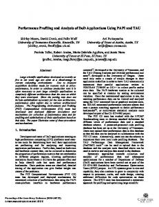
2. UML IN SYSTEM MODELING In Koski, the design flow is fully-automated and governed by UML models. The UML models are designed according to a well-defined UML profile for embedded system design, called TUT-Profile.9 The profile introduces a set of UML stereotypes, which categorize and parameterize model elements to enable automation in the analysis and implementation. The TUT-Profile divides UML modeling into the design of application model, architecture model and mapping model. The application is modeled independently of an architecture. An application model defines both the functionality and structure of an application. In TUT-Profile, application process is an elementary unit of execution, which is implemented as an asynchronously communicating Extended Finite State Machine (EFSM) using UML statecharts. Each process contains local process context, i.e. state information and internal variables. The application processes are executed on a multiprocessor SoC in a distributed manner. Correspondingly, the architecture is modeled independently of an application. An architecture model describes the used hardware components including processing elements and communication architectures. Processing elements can be general purpose processors as well as dedicated hardware accelerators, and they execute the application processes as defined in the mapping model. Koski enables the fully automated implementation of a multiprocessor SoC on FPGA according to the UML models. It comprises commercial design tools (Telelogic Tau G2, Altera Quartus II) and self-made tools. According to the application and mapping models, Koski builds distinct processor executables for each processor enabling the application to be executed a distributed manner on a multiprocessor SoC. Using the architecture model, Koski synthesizes the hardware configuration for FPGA. When an application is executed, performance characteristics can be collected on FPGA and observed on a workstation using an execution monitor as presented in Fig. 1. The monitor shows the processors implemented on FPGA, application processes executed on each processors, and the utilization of each processor. Further, any platform or application specific statistics can be measured on FPGA, and the monitor can visualize them in a
graph form. For example, we could observe dynamic memory consumption and communication activity as well as application throughput and delays.
Figure 1. Execution monitor shows the mapping of application processes and the utilization of each processor in real-time.
3. MULTIPROCESSOR SOC PLATFORM We have implemented the multiprocessor SoC platform on an Altera Stratix II EP2S60 FPGA.10 The current implementation contains up to five Nios II processor modules and dedicated hardware modules, such as hardware accelerators and interfaces to external devices. With a larger FPGA device, such as Stratix II EP2S180,11 up to 15 processor modules could be used. The clock frequency of the platform is 50 MHz. The coarse-grain Intellectual Property (IP) blocks are connected using a Heterogeneous IP Block Interconnection (HIBI) on-chip communication architecture.12 Each module has a HIBI wrapper that connects the module with HIBI. The structure of the multiprocessor platform on FPGA is presented in Fig. 2. The processor modules are self-contained having local memories; there is no shared memory in the architecture. Each processor module contains Nios II processor core, timer units, cache and memory. Further, each NIOS II processor executes a local copy of eCos Real-time Operating System (RTOS).13 One of the processor modules is a control processor, which has access to the Ethernet and RS-232 controllers on the FPGA board. The rest of the processor modules are application processors, which execute UML modeled applications in a distributed manner. The control processor implements a TCP/IP stack and provides this service to the application processors. Further, the control processor is used for debugging purposes and platform management.
Figure 2. Multiprocessor SoC platform on FPGA.
The platform contains also a radio interface module, which implements a full hardware interface to a WLAN radio on the FPGA board. The WLAN radio is Intersil HW1151-EVAL MACless radio transceiver implementing the physical layer of 802.11b (not MAC layer).
4. DYNAMIC POWER MANAGER The dynamic power manager has three main components, which are utilization observer, process remapper, and clock manager. All these are implemented as software that is executed on the control processor. Further, the clock manager controls a clock-gating circuitry that is implemented on the FPGA logic.
4.1. Utilization Observer The main task of the utilization observer is to decide on the required number of active application processors for the current workload. The decision is made according to the average utilization of the active application processors. Each active application processor collects its utilization statistics continuously. The processor utilization is calculated by measuring the time spent in the idle thread of RTOS. The utilization statistics are sent to the utilization observer on the control processor at controllable intervals of time. In this study, the utilization statistics are sent once a second. The behavior of the utilization observer is based on the predefined threshold values on the average utilization of the active application processors. If utilization crosses the upper (U T ILmax ) or lower threshold value (U T ILmin ) for a certain period of time, the utilization observer increases or decreases the number of active application processors, respectively. The current implementation of the utilization observer decides on the required resources using the utilization statistics only. We could use other platform and application specific statistics also. For example, the activity of communication architecture and different delays in application level would be useful parameters.
4.2. Process Remapper The process remapper resolves the mapping of application processes according to the number of active application processors. The used remapping algorithm balances the utilization of each active application processor. The algorithm assumes that all processes have equal workloads, which enables simpler implementation, but causes some uncertainty in remapping decisions. The algorithm is presented in Fig. 3, and it works as follows. First, the algorithm randomly selects a process from the processor that has the highest utilization at the moment. Second, the algorithm remaps the selected process to the processor currently having the lowest utilization. Third, the utilization of each processor is estimated using the new mapping. If the difference between the highest and lowest utilizations is above a set threshold value (U T ILdif f ), the algorithm iterates and goes back to the first step. The new iteration is carried out with the re-estimated processor utilizations. The processes that are already remapped are not allowed to be remapped again to prevent the ping-pong effect. The iterations are continued until a well-balanced mapping is found. When the algorithm has finished its work, the process remapper sends the new mapping to the application processors, which suspend the execution of an application and start the remapping processes. Each application processor has the code for all application processes, which simplifies the process remapping. Thus, we only have to move the context of each application process to a new target processor and activate the process on the processor. When the remapping is finished, the application processors resume their execution. The process remapper informs the clock manager about the activity state of each processor, i.e. which processors are active and execute processes, and which are inactive and execute no processes. The runtime environment automatically suspends the execution of the application processes for the process remapping. Thus, from the application point of view, the execution seems to be continuous. The time of the suspension is expected to be so short that no harm is caused for the applications. This issue is recalled below when discussing the measurements and method overhead.
Figure 3. Algorithm for the remapping of application processes.
4.3. Clock Manager The dynamic power manager uses clock-gating to set application processors to power-save state. Clock-gating was chosen due to three reasons. First, clock-gating is conceptually simple and requires only a small amount of additional hardware. Second, clock-gating preserves the state of a processor enabling very short wake-up recovery time and only a small performance overhead. Third, clock-gating is the only technique of dynamic power management that can be generally used with today’s commercial FPGAs, unlike partial supply shutdown, power-gating, and dynamic voltage and frequency scaling.14
4.4. Clock-Gating Circuitry The clock manager controls the clock-gating circuitry that includes a dedicated clock gate for each processor module. The clock gates freeze the clock signals of the inactive processor modules including the processor cores, caches and memories. All frozen components preserve their states and continue their execution immediately after having a running clock. The size of the circuitry on FPGA is very small, only 33 logic cells.
5. TEST CASE SETUP The evaluation of the dynamic power manager was performed with a WLAN MAC protocol (TUTMAC) as a test case application. TUTMAC is a dynamic reservation Time Division Multiple Access (TDMA) MAC protocol for TUTWLAN.15 TUTMAC solved the problems of scalability, Quality of Service (QoS) and security present in standard WLANs. Several configurations have been developed for different purposes and platforms. Here we consider one configuration of the TUTMAC protocol. The protocol contains functions for Cyclic Redundancy Check (CRC) and encryption. CRC is performed for headers with CRC-8 algorithm, and for payload data with CRC-32 algorithm. The encryption is performed for payload data using an Advanced Encryption System (AES) algorithm. The algorithm encrypts payload data in 128-bit blocks, and uses an encryption key of the same size. The main functional components and protocol functions are presented in Fig. 4.
Figure 4. Main functional components and protocol functions of the TUTMAC protocol.
The protocol functions are performed for every packet sent and received by a terminal. Thus, their performance becomes significant, especially, when the data throughput increases. Further, the radio channel access has to maintain accurate frame synchronization in the TDMA scheduling, which set tight real-time requirements. To guarantee a certain performance (throughput, latency) and accuracy (TDMA scheduling) for the protocol, tight real-time constraints are addressed to the protocol processing. Depending on the implementation, the algorithms may also need hardware acceleration to achieve adequate delays for data. In this work, we use a full software implementation.
6. MEASUREMENTS First, we evaluated the power consumption of clock-gated multiprocessor platform to find out how much clockgating can decrease the power consumption on FPGA. Second, we evaluated the method overhead to reveal the cost of dynamic power management. Third, we considered the dynamic power management and application execution as a whole to see how the workload of the test case application influences the utilization and power consumption in practice.
6.1. Power Consumption The power measurements were performed from the main power supply of the FPGA board. This approach was taken because we were unable to isolate the FPGA chip from the board. It is difficult break down the power consumption of the FGPA chip and other devices on the board. Thus, we consider the power consumption of the whole FPGA board, which corresponds the board-level (or system-level) situation, not only the chip-level. We measured the power consumption with 1–4 active application processors, which executed the TUTMAC protocol in a distributed manner. The results are presented in Table 1. If we freeze three application processors, i.e. TUTMAC is executed on a single application processor, we can save up to 984 mW compared to four active application processors. This corresponds up to 21.7% of the total FGPA board power consumption. The measurements revealed that the dynamic power management with clock-gating on FPGA has definite influence even on the board-level power consumption in FPGA systems. Table 1. Average power consumption of the FPGA board.
Table 2. Delay of the process remapping is dependent on the number of involved application processors. Remapping within one processor is not defined.
According to the presented results, we can state that our approach has significance on FPGA systems. Further, we can assume that presented methods would result significant advantages in ASIC implementations also.
6.2. Method Overhead The method overhead was evaluated to determine the cost of power management in terms of execution time. Two separate cases are considered. We consider utilization observing to find out the cost of measuring and processing the utilization statistics. Further, we consider process remapping to reveal the performance loss when the dynamic power manager decides on changing the number of active application processors. 6.2.1. Utilization observing The cost of utilization observing determines the computation overhead caused by measuring the utilization statistics on each application processor and the execution of the utilization observer on the control processor. The utilization statistics is gathered and the utilization observer is executed periodically with one second intervals. This frequency is a good basis as the overhead remains clearly insignificant (< 0.001%), and thus, it does not disturb the execution of an application at all. 6.2.2. Process remapping The cost of process remapping determines the computation overhead in the remapping of application processes. This cost is paid always when the utilization observer decides to change the mapping. During the remapping, the execution of an application is suspended, which makes it a very critical operation in a real-time system. The measurements showed that the number of processors involved in remapping was the only dominant factor in the delay of remapping. Thus, the number of remapped processes and the amount of transferred data are negligible. The delays of process remapping with different numbers of involved processors is presented in Table 2.
6.3. Application Case Study The TUTMAC protocol causes varying workload on the platform depending on data throughput as presented in Fig. 5. We sent data with certain throughput rates over TUTMAC and measured the utilization of active application processors. Measurements with different numbers of active application processors emulated different power-save states. The mapping of TUTMAC to different numbers of active application processors8 is as follows. On one processor, all the main functional components of TUTMAC were mapped to a single processor. On two, three and four processors, the reception data processing, transmission data processing and AES encryption are mapped to own processors. This kind of mapping strategy was chosen because it is intuitive to distribute the main functional components of an application. This is reasonable due to two reasons. This minimizes IPC communication as we assume that the communication inside each main component is more active than between the main components. Further, we can assume that the main components have high parallelism due to their independence. In TUTMAC, the transmission and reception data processing and TDMA scheduler can be executed in parallel without constant dependence, because they handle packets that are in different phases of processing.
Figure 5. Average utilization of active application processors according to the varying throughput over TUTMAC. With only one application processor, TUTMAC was unable to achieve the highest throughput (500 kb/s).
Figure 6. Power consumption of the FPGA board changes according to the varying throughput when we use the dynamic power management. U T ILmin = 30%, U T ILmax = 60%, and U T ILdif f = 28%-units.
The presented average utilization shows that with low throughput rates there are plenty of unnecessary resources. Thus, it is reasonable to set certain processors to a power-save state to decrease power consumption. If throughput (and utilization) increases, we may unfreeze processors to get more computing power. Fig. 6 presents the power consumption of the FPGA board according to the varying throughput. Without dynamic power management the power consumption is constant regardless of throughput.
7. CONCLUSIONS This paper presented a novel approach for the dynamic power management of UML modeled applications that are executed in a distributed manner on a multiprocessor SoC. The presented method exploits runtime process remapping and power management using clock-gating. Measurements on FPGA proved 5 to 21% savings in the power consumption of the whole FPGA board. The
method overhead was measured to be insignificant, and that it does not disturb the execution of an application at all. Also, the WLAN terminal was discovered to be very suitable for the proposed scheme as with low throughput we achieved reduced power consumption. This proof of concept provided very promising results with the board-level power consumption, even though, FPGA is a very challenging device for power-aware computing. Unlike many ASIC technologies, standard FPGAs provide very limited possibilities in using more advanced power management techniques, such as dynamic voltage and frequency scaling, and power-gating. Especially the latter, could have a perfect match with the presented approach and provide significant savings in the power consumption. The future work with the dynamic power management will include the development of more sophisticated methods in runtime resource allocation and process remapping as well as architecture exploration. Further, the general capacity management and dynamic power management techniques will be improved.
REFERENCES 1. S. Leue and P. A. Oechslin, “On parallelizing and optimizing the implementation of communication protocol,” IEEE/ACM Transactions on Networking 4, pp. 55–70, Feb. 1996. 2. M. J. Irwin, L. Benini, N. Vijaykrishnan, and M. Kandemir, Multiprocessor Systems-on-Chip, ch. Techniques for Designing Energy-Aware MPSoCs, pp. 21–47. Morgan Kaufmann, 2004. 3. S. Sriram and S. S. Bhattacharyya, Embedded Multiprocessors: Scheduling and Synchronization, Marcel Dekker, 2000. 4. P. Yang and F. Catthoor, “Dynamic mapping and ordering tasks of embedded real-time systems on multiprocessor platforms,” in Lecture Notes in Computer Science, 3199, pp. 167–181, Springer-Verlag, 2004. 5. J. Khan and R. Vemuri, “Battery-efficient task execution on reconfigurable computing platforms with multiple processing units,” in Proceedings of the 19th IEEE International Parallel and Distributed Processing Symposium, 4, p. 155b, 2005. 6. T. L. Martin, D. P. Siewiorek, A. Smailagic, M. Bosworth, M. Ettus, and J. Warren, “A case study of a system-level approach to power-aware computing,” ACM Transactions on Embedded Computing Systems 2, pp. 255–276, Aug. 2003. 7. L. Benini, A. Bogliolo, and G. D. Micheli, “A survey of design techniques for system-level dynamic power management,” IEEE Transactions on VLSI Systems 8, pp. 299–316, June 2000. 8. M. Set¨ al¨ a, P. Kukkala, T. Arpinen, M. H¨ annik¨ ainen, and T. D. H¨ am¨al¨ ainen, “Automated distribution of UML 2.0 designed applications to a configurable multiprocessor platform,” in Proceedings of the Embedded Computer Systems: Architectures, MOdeling, and Simulation, 2006. 9. P. Kukkala, J. Riihim¨ aki, M. H¨ annik¨ ainen, T. D. H¨ am¨al¨ ainen, and K. Kronl¨ of, “UML 2.0 profile for embedded system design,” in Proceedings of the Design, Automation and Test in Europe, 2, pp. 710–715, Mar. 2005. 10. T. Arpinen, P. Kukkala, E. Salminen, M. H¨ annik¨ ainen, and T. D. H¨ am¨al¨ ainen, “Multiprocessor platform with RTOS for distributed execution of UML 2.0 designed applications,” in Proceedings of the Design, Automation and Test in Europe, pp. 1324–1329, Mar. 2006. 11. Altera homepage, Dec. 2006. http://www.altera.com. 12. E. Salminen, T. Kangas, T. D. H¨ am¨al¨ ainen, J. Riihim¨ aki, V. Lahtinen, and K. Kuusilinna, “HIBI communication network for system-on-chip,” Journal of VLSI Signal Processing 43, pp. 185–205, June 2006. 13. A. Massa, Embedded Software Development with eCos, Prentice Hall Professional Technical Reference, 2002. 14. V. Degalahal and T. Tuan, “Methodology for high level estimation of FPGA power consumption,” in Proceedings of the Asia and South Pacific Design Automation Conference, 1, pp. 657–660, 2005. 15. M. H¨ annik¨ ainen, T. Lavikko, P. Kukkala, and T. D. H¨ am¨al¨ ainen, “TUTWLAN - QoS supporting wireless network,” Telecommunication Systems - Modelling, Analysis, Design and Management 23(3,4), pp. 297–333, 2003.