PETROCHEMICALS and GAS PROCESSING
Dynamic simulation of a demethaniser column An implicit approach-based method for calculating distillation column dynamics has been used to model time-dependent effects of independent disturbances with a demethaniser column. Startup and shutdown sequences can be tested in this way M Sadrameli M Shakeri J Towfighi Chemical Engineering Department, Modares University
D
ynamic simulation has been applied to the second 50-tray demethaniser column at the Arak olefin plant in Iran, in which methane, hydrogen and carbon monooxide are separated from the heavier components of the cracked gas. The model is based on the implicit approach, where the time dependent variations of inventory, temperatures, liquid and vapour flows and compositions are superimposed at each time step on the steady-state solution. The implicit method, rather than the explicit, is used to solve the non-linear differential equations resulting from the heat and mass balances. This is because, for a relatively large-enough integration step using the implicit method, the numerical solution may become unstable even if the response of the model equations is dynamically stable. For these purposes, the implicit method does not incur the same stability limitations as the explicit method. The results of the computer programs have been compared with the plant data and good agreement has been obtained. Thermal steam cracking of hydrocarbons in tubular furnaces produces a considerable part of the world ethylene production. Global ethylene demand is projected to reach 136 million tons/year by 2010. The Middle East and East Asia will be the fastest growing regions. Polyethylene is the driving force behind ethylene consumption and this end-use pattern is not expected to change significantly. Gas-advantaged countries, such as those in the Middle East, will have a considerable competitive advantage due to low ethane feedstock costs. These feedstock costs will be the driving force behind new ethylene production capacity in the Middle East. Derivatives based on low cost ethylene will therefore be able to compete effectively in both East Asian and European markets. The feedstocks for steam cracking units range from light paraffinic hydrocarbon gases to various petroleum frac-
tions and residues. The properties of these feedstocks are documented in various publications and technical journals. The thermal cracking reactions are principally bond-breaking, and a substantial amount of energy is needed to drive the reaction towards olefin production. The simplest paraffin and the most widely used feedstock for producing ethylene is ethane, such as at the Arak olefin facility. The cracking of ethane is highly endothermic, so it is favoured at higher temperature and lower pressures. Cracking ethane can be visualised as a free radical dehydrogenation reaction, where hydrogen is a coproduct. An ethylene unit can be considered to consist of two sections. The first is the hot section, where thermal cracking of hydrocarbons occurs in tubular reactors at very high temperatures. Steam is added to the feedstock to reduce the partial pressure of the hydrocarbons in the tubular coils. A free radical mechanism is known to be involved in the primary decomposition of saturated hydrocarbons to olefins, methane and hydrogen. Ethane, which is one of the dominant feedstocks for ethylene manufacture, can yield over 85% of the theoretical possible yield of ethylene, when processed through modern pyrolysis furnaces. Significant quantities of methane are also produced. Traces of diolefins, aromatics, heavier olefins and paraffins are also detected in the reactor effluent. The second section is the cold section where the cracked gas is cooled and separated into products in the distillation columns. One of the most important stages of the separation process is the demethanisation column, which is discussed later in this article. All ethylene or olefins manufacturing processes incorporate a great number of unit operations involving catalytic and non-catalytic reactions, absorption and adsorption, fractionation (demethanisation and others), heat exchange and compression arranged in a complex
111 P T Q SPRING 2003
w w w. e p t q . c o m
array to achieve the production of high purity ethylene and other important olefins, such as propylene. The typical plant contains hundreds of important pieces of equipment. For certain services, a single piece of equipment cannot be economically manufactured with sufficient capacity and therefore multiple pieces (for example, two demethanisers) and their supporting systems must be employed. Thermal steam cracking olefins plants employ extreme temperatures ranging from over 860ºC at the outlet of the pyrolysis furnaces to –170ºC in the cryogenic hydrogen-methane separation system. These extreme temperatures call for the application of a multitude of materials of construction, which could include molybdenum alloy for the methanator, which is exposed to high hydrogen partial pressures at elevated pressures. The complexity of the process and the large number of different pieces of equipment require an extensive and complex automation control system. The typical plant may contain thousands of measuring points for temperature, pressure, levels, flows and compositions. Hundreds of control loops are also involved. Systems have been developed that call for the sharp separation of the C3 and heavier components, from the pyrolysis gas as the first fractionation step. Although thermodynamic theory declares all paths to the pure products are equivalent, most licensors of ethylene process technology appear to prefer demethanisation as the first sharp fractionation step, which is why dynamic simulation of the Arak plant’s second demethaniser has been performed. In addition, specialised modular simulation programs are also applied to determine the mass and energy balances for the refrigeration cascade and the steam system, which has been discussed in previous publications. Other software-based programs have been developed to perform the process design calculations for various types of
PETROCHEMICALS and GAS PROCESSING
Products characteristics from column T-302
Feed characteristics in column T-302 Stream Number
310
323
Stream phase Vapour Liquid Temperature, °C –25.6 –62.13 Pressure (bar) 31.95 31.65 Flow rate (kg/hr) 8264 16573 Flow rate (kmole/hr) 356.9 631.2
Stream Number
324
325
Liquid –97.98 31.57 10525 475.9
Liquid –125.96 31.51 4424 254.88
Table 1
Phase Temperature, °C Pressure (bar) Flow rate (kg/hr) Flow rate (kmole/hr)
310
323
324
316
320
Liquid –5.59 31.77 27596 948.2
Vapour –96.49 31.07 8031 513.1
Liquid –96.49 31.07 4159 257.4
Vapour –94.24 31.27 19660 1232.8
Liquid –5.59 31.77 4159 257.4
Table 2
equipment including the pyrolysis heaters, fractionating trays and heat exchangers.
Demethaniser Cryogenic operations in an olefins plant, such as the Arak facility, involves the successive chilling of the pyrolysis gas in heat exchange with boiling refrigerant and with cold process streams that have been vaporised and/or reheated. The pyrolysis gas can be sent to a high-pressure demethaniser, which accomplishes the removal of methane from the condensate. Ethylene refrigerant boiling in the reflux condenser at about atmospheric pressure controls the dew point temperature of the overhead product.
The ethylene contained in the overhead product is usually recovered either through condensation and recycling to the main compressor or through condensation with refrigeration generated by a turboexpander. However, only condensates are usually sent to the demethaniser in most cases, where complete separation of methane is achieved from ethylene and heavier components. Condensing propylene refrigerant supplies the necessary heat to the reboiler, and vaporising ethylene condenses reflux and some of the overhead prod-
uct. The overhead product therefore consists mostly of methane with a small amount of hydrogen, which enters the tower dissolved in the condensates. Dynamic simulation is a process engineering design tool that predicts how a process and its controls respond to various upsets as a function of time. It also can be used to evaluate equipment configurations and control schemes and to determine a design’s reliability and safety before capital is committed to a project. Dynamic simulation models used for process design are not based on transfer functions, as found in many operator-training simulators, but on fundamental engineering principles and actual physical equations governing the process. It also provides controller-tuning parameters for use during startup. In many cases, accurate controller settings can prevent expensive shutdown and accelerate plant start-up. A new method for the dynamic simulation of distillation columns can be used to model time-dependent effects of independent disturbances for the demethaniser process. The model is based on an implicit approach, where the time dependent variations of inventory, temperatures, liquid and vapour flows and compositions are superim-
posed at each time step on the steadystate solution. As previously mentioned, dynamic simulation was performed on the second demethaniser column with 50 trays in which methane, hydrogen and carbon monooxide are separated from the heavier components of the cracked gas. The implicit method is used to solve the non-linear differential equations resulting from the heat and mass balances.
Process description The olefin plant’s 50-tray second demethaniser column (T-302) has four feeds. The first feed, which is the top stream of the first demethaniser column, is fed to tray 28. Streams 323 from vessel V-302 enter tray 34, and finally streams 324 and 325 each are divided into two streams, which are fed to trays 42, 40, 46 and 48 respectively. The top products of the demethaniser partial condenser consist of streams 316, 318 and 319 from which stream 319 is recycled to the tower. Tables 1 and 2, respectively, show the feed and products characteristics of column T-302.
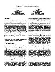
Steady state simulation A schematic diagram of a complex distillation column with two feeds and
V2
D
F-1
F1 L1
FX1
W1 (liquid)
VF1
F2
F
W2 (vapour)
N B
Figure 1 Complex multifeed distillation column with two feeds
Figure 2 Feed tray inlet and outlet
112 P T Q SPRING 2003
PETROCHEMICALS and GAS PROCESSING
Comparison of simulation results for steady state conditions Stage
PROII T, °C
1C 2 4 6 8 10 15 20 25 27R
–48.8 –31.4 –25.4 –24.7 –24.2 –22.1 –7.5 –7.1 –6.0 –0.1
Simulation T, °C –48.8 –31.6 –25.3 –24.6 –24.0 –22.0 –7.4 –7.0 –5.9 –0.3
PROII Simulation V, kmole/hr V, kmole/hr 189.8 681.6 706.4 707.7 704.6 690.1 1006.1 1014.1 1006.8 953.4
189.8 681.6 706.7 709.7 708.7 704.8 966.4 969.6 956.1 896.4
PROII Simulation L, kmole/hr L, kmole/hr 371.8 389.2 398.1 396.9 390.2 1202.4 1330.4 1334.1 1312.9 320.04
371.8 384.1 399.5 399.6 397.7 1189.6 1288.6 1289.1 1258.6 320.04
Table 3 two-side stream is shown in Figure 1,, while Figure 2 represents the inlet and outlet for the feed tray. The input data for a distillation column are usually composed of column pressure, number of trays, flow rates, compositions, and properties of input feeds, positions of entering feeds and products, reflux ratio and type and flow rate of condenser. The model includes equations for the enthalpy and mass balances and equilibrium conditions. The number of equations are: (N+2)(2c+3) with (N+2)(2c+3)+3 variables. Since the number of parameters is
more than the number of equations, three variables, usually D, L1 and column pressure, P, must therefore be specified. Numerical techniques have been used for the static simulation of distillation columns, based on the iterative techniques of Lewis and Matheson and Thiele-Geddes that have been used since 1963. Both the Lewis Matheson and ThieleGeddes methods have been used long before the availability of digital computers. It should be noted that these methods suffer from numerical difficulties
113 P T Q SPRING 2003
that can prevent convergence in certain cases. The stage-to-stage calculation used in the Lewis Matheson method proceeds from the top down and from the bottom of the column up, and may be subject to large truncation-error buildup. The Thiele-Geddes method avoids that difficulty, but numerical instabilities arise as soon as the stage-to-stage calculation crosses a feed stage. Then, a different term appears in the equations, which may result in a serious loss of significant digits, making the Thiele-Geddes method basically unsuited for multiple-feed columns. Because of all these numerical difficulties, neither of these methods is commonly implemented in modern computer algorithms. Nevertheless, their methodology is still very instructive. In the first method the condenser and reboiler mole fractions were considered independent, while in the second technique, the temperatures of each stage were considered independent. In the solution of non-linear differential equations with iterative techniques, the convergence is not only dependent on the independent variables, but also on the sequence of equation solution. Holland investigated the sequence of the equation solution and suggested that for the
PETROCHEMICALS and GAS PROCESSING
Conditions of demethaniser column T-302
Comparison of results with plant data Column, T302 Temperature, °C Pressure, Bar Flow rate, kg/hr Reboiler duty, MMkCal/hr
Simulation Overhead –93.9 – 8075.7
Simulation Bottom –6.64 31.5 –
Plant data Overhead –96.0 – 8400
Plant data Bottom –5.6 28.8 –
–
1.68
–
1.32
Feed flow rate at boiling temperature: 100 kgmole/hr Number of components: 3 Compositions: 60% C3H8, 20% C4H10, 20% C6H14 Feed temperature: –62.13 Condenser flow rate (liquid): 50 kmole/hr Condenser vapour in: 150 kmole/hr Theoretical number of trays: 5 Feed tray: 4 Condenser and Reboiler types: Total Reboiler type: Total Column pressure: 300 Psia Unsteady condition (different feed composition): C3H8: 10%, C4H10: 40%, C6H14: 50%
Table 4 convergency, using the Theta method is necessary.
Calculation algorithm A sum of Tj’s and vapour flow rates, Vj’s are assumed as a first guess. The sum of liquid flow rates can be calculated from the mass balance equations. By assuming the first stage guess, the temperatures and flow rates of the next stages are calculated. For the evaluation of the software, the simulation results for the steady-state condition have been compared with the PROII process simulation package. The input data are listed as follows: Mass flow rate: 629.8 kgmole/hr Feed composition: 24.196% CH4, 59.523% C2H4, 8.748% C2H6, 6.604% C3H6, 9.29% C3H8 Temperature: –62.13°C Number of trays: 50 Efficiency: 50% Feed tray: 10 Condenser type: Partial Reboiler type: Total The results of the simulation are presented in Table 3. As it shows, there are some discrepancies between the L and V
values, which are caused by the type of equation of state, which is used in the model and in the PROII simulation package (SRK). Table 5 However, with regard to temperature distribution and vapour and liquid flow rate in the column, there is very close agreement (between the results of the two different simulation packages), which proves the accuracy of the simulation programme for the steady state condition. The steady state results of the model are also compared with some of the plant data of the Arak olefin plant. They are listed in Table 4. The difference between the experimental data and simulation results is due to the dramatic change in the feedstock in comparison with the design case.
Non-linear behaviour Historically, beginning in the late 1940s, dynamic simulation of distillation has been linked to analogue computation. In the last 20 to 30 years, digital computers, with their increased speed and capability, have become the machines of
choice for process unit dynamic simulations. Over the years, specialised simulation software has been developed and is extensively marketed by organisations specialising in process automation. In theory, these simulation languages relieve the engineer of knowing anything about numerical integration. Therefore, these packages make it easier for the plant engineer to set up and solve problems that involve processrelated delays, non-linear behaviour and the interaction among different control loops. This is particularly the case with heat and mass transfer occurring in a real distillation or fractionation column such as demethanisers typically used in olefins plants. Here, the demethaniser operation is translated into a quantitative mathematical model. Due to the very large number of equations needed for the rigorous description of the “system”,
1.00
2.1 1.9
Qr 0.98
1.5
Mole fraction
Duty, MMkCal/hr
1.7
1.3 1.1
Methane in distillate
0.96 0.9
Qc
0.7 0.5 1,500 1,550 1,600 1,650 1,700 1,750 1,800 1,850 1,900
0.94 1,500
Feed flow rate, Kmol/hr
1,550 1,600 1,650 1,700 1,750 1,800 1,850 1,900 Feed flow rate, Kmol/hr
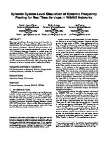
Figure 3 Effect of feed flow rate variation on condenser and reboiler duty
Figure 4 Effect of feed flow rate on the purity of the condenser product
114 P T Q SPRING 2003
PETROCHEMICALS and GAS PROCESSING the calculations are, of course, made with the use of a computer that incorporates some integration methodology. Therefore, the simulation (in this case) can mimic the non-linear behaviour of the system. Mathematically, dynamic simulation has used two distinct methods of solution: explicit (Euler method) and implicit. Briefly, one of the simplest explicit methods (Euler method: where the state variables are calculated explicitly at each integration step from the values resulting from the previous step) numerically integrates, one-by-one, differential equations that characterise distillation at each time increment, using values of the last increment’s variables for the integration. The Euler method is the simplest for the solution of ordinary differential equations because it assumes that the derivative functions are constant over a small integration interval. Thus the changes in liquid flow on a tray are considered to be independent of liquid-flow changes on the tray above until the end of the time interval. The integration interval, ³T, affects the accuracy of the numerical integration of the differential equations and the computer time required to perform the computations. This time delay introduces errors, which are often unacceptable in the presence of significant disturbances. For the enthalpy, vapour pressure, and Kvalue calculation, thermodynamic correlation of SRK has been used. For the dynamic condition the feed composition has been altered to 10% C3H8, 40% C4H10, 50% C6H14. Some of the results of the simulation including flow rate distributions are shown in Figures 3 and 4. For the evaluation of the dynamic model the results of the computer program have been compared with a similar separation column in the literature data. The conditions of the column at steady state are listed in Table 5.
Azad University, during the time this article was being prepared for publication. He graduated from Sharif University of Technology, Tehran in 1995. His postgraduate and professional areas of interest include dynamic simulation and modelling of refinery and petrochemical processes. J Towfighi is an associate professor of chemical engineering at Tarbiat Modares University and a graduate of Shiraz University, Iran. He holds an MSc and PhD in chemical engineering from Leeds University and his research interests include heat recovery, heat transfer, modelling and simulation of petrochemical processes, especially olefin technology. He is presently head of the chemical engineering division in the department and consultant of energy conservation projects in oil and energy ministries.
M Sadrameli is an associate professor of chemical engineering at Tarbiat Modares University, Tehran. He graduated from Sharif University of Technology, Tehran, and holds MSc and PhD degrees in chemical engineering from Leeds University, UK. His research interests are heat recovery, heat transfer, modelling and simulation of petrochemical processes, particularly with regard to olefin technology. He is presently head of the chemical engineering division in the department and consultant of energy conservation projects in oil and energy ministries. Email:
[email protected] M Shakeri was a postgraduate student of the chemical engineering department,
115 P T Q SPRING 2003