Purdue University
Purdue e-Pubs International Refrigeration and Air Conditioning Conference
School of Mechanical Engineering
1998
Dynamic Simulation of Multi-Compressor Food Retail Refrigeration Systems Y. T. Ge Brunel University
S. A. Tassou Brunel University
D. Datta Brunel University
K. Y. Chan Brunel University
Follow this and additional works at: http://docs.lib.purdue.edu/iracc Ge, Y. T.; Tassou, S. A.; Datta, D.; and Chan, K. Y., "Dynamic Simulation of Multi-Compressor Food Retail Refrigeration Systems" (1998). International Refrigeration and Air Conditioning Conference. Paper 419. http://docs.lib.purdue.edu/iracc/419
This document has been made available through Purdue e-Pubs, a service of the Purdue University Libraries. Please contact
[email protected] for additional information. Complete proceedings may be acquired in print and on CD-ROM directly from the Ray W. Herrick Laboratories at https://engineering.purdue.edu/ Herrick/Events/orderlit.html
DYNAMIC SIMULATION OF MULTI- COMPR ESSOR FOOD RETAIL REFRIGERATION SYSTEMS Y. T. Ge~ S. A. Tassou, D. Datta and K. Y. Chan Department of Mechanical Engineering Brunei University Uxbridge, Middlesex, UB8 3PH UK
ABASTRACT This paper provides results of experimental investigations on the effect of on/off control parameters on the efficiency and stability of the control of multi-compressor refrigeration systems in retail food stores. The paper also reports on a simulation model that is being developed to enable the investigation of alternative control strategies and design options for supermarket refrigeration systems. The model is based on the TRNSYS simulation environme nt and considers the geometric characteristics of the components, controls and frosting on the evaporator coils. It can be employed for the investigation and comparison of alternative system control strategies such as, on/off and PID controls, and design options. The usefulness of the model is illustrated by comparing the performance of an on/off controlled multi-compressor refrigeration system with that of a system employing variable speed control on one of the compressors.
INTRODU CTION Refrigeration is a major user of energy in the UK, accounting for around 17% of total electrical energy consumption [I]. It is estimated that supermarket refrigeration nation-wide, is responsible for the consumptio n of 6 9.2 x 10 kWh costing in excess of £480 million. A large proportion of this energy can be saved through better system component integration and control. Most current supermarket refrigeration systems employ multiple compressors connected in parallel and piped to common suction and discharge manifolds. This arrangeme nt allows for capacity control, by means of on/off switching of the compressors in response to the desired suction pressure setpoint [2]. On-off control is widely employed, due to its reliability and low cost. However, frequent on/off switching of the compressors is not desirable because short cycling results in abrupt changes in suction pressure and imposes severe stresses on the compressor [3]. This increases wear and tear of the compressor components and may finally lead to compressor failure. To avoid the disadvantages of on/off control and achieve better system efficiency more sophisticated control strategies should be investigated and utilized. The application of microprocessor-based systems to the control of refrigeration plant in order to provide accurate temperature control of display cabinets has greatly improved in recent years. So much so, that the implement ation of control strategies can be undertaken with ease. A number of strategies have evolved but in the majority of cases they still rely on the on/off switching ofthe compressors. Better refrigeration system control and higher energy efficiencies can be achieved if compressor on/off control is replaced by variable speed control to closely match the variation in load using PID or more sophisticat ed control strategies based on predictive or ·intelligent' schemes. Full-scale experimentation on alternative control strategies can be disruptive and very expensive and the use of system simulation techniques provides an ideal vehicle for the investigation of alternative control strategies and design options for supermarket refrigeration systems. This paper presents results of simulation studies in the search for improved controls for multi-compressor supermarket refrigeration systems. The simulation results have been validated on a small scale experimental test rig in the laboratory.
253
EXPERI MENTA L REFRIG ERATIO N SYSTEM in the laboratory. All validation experiments have been perfonned on a mini-supennarket refrigeration system The instrumental pack. The system consists of two refrigerated display cabinets served by a mini multi-compressor r system humidifie and unit handling display cabinet is situated an environmental chamber, which is fitted with an air to provide humidity and space temperature control. semi-hennetic compressors. The mini compressor pack is comprised of three unequal capacity DWM or pack and provide compress the above level high at mounted are rs Two Searle MDS twin fan air-cooled condense independently, switched being fan each with parallel in piped are s heat rejection to the ambient. The condenser flow rate mass its and R22 is employed t refrigeran The pressure. g condensin the which gives a five-stage control of ors is recorded using a is measured using a Coriolis mass flow meter. The power consumption of the compress 'Prime' series 500 power transducer. g or monitoring The control system is comprised of a central network 'Supervisor', which is capable of controllin switches controller The network. each on rs two networks of up to 32 controllers or pressure/temperature transduce requires controller the up Setting line. suction the in compressors on or off in response to the rise or fall of pressure delay. time a and skip stage a al, differenti pressure a the selection of four parameters, the target suction pressure, which logs pressures, The perfonnance of the system is monitored by a computer-based data logging system, test rig and data logging temperatures, flow rates, and power consumption at regular intervals. More details on the system have been reported by Chan and Tassou [4].
MODEL DESCRI PTION TRNSYS simulation The model developed for the above laboratory refrigeration system is based on the d component models develope on based environment. TRNSYS provides the capability to construct system models and a specification of the interconnecting piping. the compressors, The model is organised functionally into two major sections. The first section combines the low side section, second The unit. high-side d interrelate an into routines condensers, and thennal expansion valve the desired until sections two these between iteratively proceed ns calculatio unit, contains the evaporator model. The simulate can two sections, overall thennal balance is obtained. A control subroutine, which couples together these r are evaporato and r different control schemes and operating strategies. The supply air parameters for the condense Input s. condition space and time dependent to facilitate the simulation of the effect of the variation of ambient parameters to the system model include: • • • • • •
the level of evaporator exit superheat (or quality), the level of required condenser sub-cooling (or quality), time dependent condenser and evaporator inlet air parameters, dimensions of components and interconnecting piping control scheme for the system starting and stopping times and time step for the simulation .
of parameters need to be To increase the speed of simulation and facilitate convergence, some initial estimates provided as follows: • the refrigerant temperature at the evaporator inlet, • the refrigerant saturated temperature at the condenser inlet, • input control functions for compressors and condenser fans. are independent of the These above three estimates are used as starting points for the iterations. The fmal results can be employed. solution initial estimates, but good initial estimates result in shorter running times. Two methods of
254
One relies on the refrigerant flow balance across the compressor and the expansion d~vice and requires detai~ed modelling of the expansion valve whereas the other relies on the achievement of the reqmred degree of superheatmg and subcooling irrespective of the type of expansion device employed. Outputs from the model include: • the instantaneous suction and condensing pressures • the cooling capacity and compressor power consumption of the system • the state of the refrigerant (pressures and temperatures) at various points in the cycle.
Compres sor model Since the compressor is the heart of the refrigeration system and the primary user of electrical power, accurate compressor modelling is important to good system performance prediction. However, a complex compressor model requires detailed hardware design parameters, which are not system specific and not easy to obtain from the manufacturers. In the present study, a fairly simple compressor model has been employed which is based on loss and efficiency terms. This model has been calibrated using data from experimental results from compressor tests in the laboratory.
Heat exchange r models
• •
The air-to-refrigerant condenser and evaporator models have been developed based on the: effectiveness vs. Ntu correlation for heat transfer of a dry coil, a modified version of the enthalpy different approach when there is dehumidification.
The two heat exchanger models are similar apart from the dehumidification algorithm employed for the evaporator modeL The calculation methods used assume that the heat exchangers consist of equivalent, parallel refrigerant circuits with unmixed flow on both the air and refrigerant sides. For each circuit, the refrigerant-side calculations are separated into computations for the superheated and two-phase regions for the evaporator and for the superheated, two-phase, and sub-cooled regions for condenser. As a part of the whole system simulation for supermarket energy, the heat exchanger models are founded based on lump method. In this case, the heat transfer for the liquid, vapor, and two-phase refrigeran t regions of the heat exchanger are computed using effectiveness vs. Ntu correlation, except for the two refrigeran t regions of evaporator with dehumidification and frosting [5][6]. Most supermarket refrigeration systems operate under frost conditions for the majority of time so modeling of frost formation is an important consideration in an overall system simulation modeL Frost formation on evaporator coils has a number of influences on the performance of refrigeration systems which include: increase in the total thermal resistance of the coil, decrease of the air flow rate, and eventual reduction of the operating efficiency of the system. The thermal resistance offrost layer and airflow rate are both dependent on the frost thickness, the density of the frost layer, and the system running time. These variables make the performance of the coil time dependent. The requirement for periodical defrosting necessitates the on/off cycling of the compress ors alongside the cycling performed to maintain the suction pressure constant during normal operation. To obtain, therefore, realistic system simulation results the dynamic frosting process on the evaporator coil should be taken into account in the evaporator modeL The present model utilizes a semi-empirical correlation developed by Malhamm ar [7] [8] [9] to model the effect of frost formation on system performance.
Control model To achieve the required evaporating temperature and stability in system operation, the suction and discharge pressures of multi-compressor supermarket refrigeration systems are normally controlled at pre-set values by cycling the compressors and the condenser fans on and off in response to changes in the suction and discharge pressure respectively.
255
control strategy employed in the control In the model a control subroutine has been developed which emulates the of standard supermarket refrigeration systems.
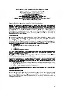
Thermo dynami c properti es software package REFPROP [10]. The refrigerant properties are calculated using subroutines from the NIST to five component-mixtures of these REFPROP can calculate the properties of a large number of pure fluids and up fluids. Model validati on model predictions were made to Comparisons between measurements with on/off control and corresponding determine the accuracy and limitations of the quasi-steady state model. and discharge pressures. It can be Figures 1 and 2 present a comparison between the actual and simulated suction suction and discharge pressures the in variation overall seen that the model is able to trace quite accurately the tion of Figure 2 reveals that examina Close fans. er condens arising from the on/off switching of the compressors and from the model, the actual obtained that to close very is pressure even though the average experimental discharge This discrepancy requires . response model the than faster is g switchin response of the discharge pressure from fan further investigation. 18,-- ------ ------ ------ ----
4,-------------------------~
3.8 '15 _3.6 ~:::~.._.. 3.4
0
5 3.2
~
1/)
a.
Ill
~,e. 14
U)
...
a.
0 ~
Q)
Q)
~
3
§ ~ 2.8
~~ lil
; E 2.6 (.) 0 u 2.4
J5
16
~""L:'
2
~
.c::: 0 u
--Simu lation I . Test 2.2 I. . =~~~ ~ 2+-----~--~= 1200 1000 800 600
i5
12
I 10
E ::::s
U)
§
0 ~
~
1
0.8
u
a. 0.6
a..
0.4 0.2
~ ~
0 600
1
•
.
600
Test
_j
800
1000
1200
lime (s)
Figure 2. Comparison of simulation with test for discharge pressure of compressor 7,----~-------------------,
1.6
a....
I
•::.-:_-::.._---..s""•m.J=Ja,.,-ti~=-=n" ['
6+------~~~====~
Figure 1. Comparison of simulation with test for suction pressure of compressor
1.4 0 § "j' 1.2
I
8
lime (s)
:;::~
:
...........,..
-
6
0
-,
z.'i's
·c:; 6 ~
~
~04 coo ~ 3
"
C'JO
c a. ::: g! 2
8 u
~--· ~1mulat1on --Tes t
800
1000
Q) - - S1mulati0ri 1 .1 --Tes t _j
0+------+-----=~====~ 1200 1000 800 600 lime (s)
1200
Time (s)
Figure 4. Comparison of simulation with test for cooling capacity of evaporator
Figure 3. Comparison of simulation with test for power consumption of compressor
256
Figure 3 presents a comparison between the power consumption obtained from the experiments and that predicted by the model. It can be seen that the model predicts quite well the maximum compresso r power consumption as well as the variation of the power arising from compressor cycling. There is a small difference between the time that one of the compressors remains switched off between cycling and this could be due to a number of reasons such as underestimation of the effect of frosting on the response of the evaporator. This is also evident from the discrepancy between the experimental and model response for the cooling capacity of the evaporator illustrated in Figure 4. The developed model can be used to investigate the effect of different control strategies on the primary control variable which is the suction pressure and the overall energy consumption of the system. A possible strategy is the application of variable speed control on one ofthe compressors. The simulation results for such a strategy are shown in Figures 5 to 7. Figure 5 presents the variation of suction pressure which as can be seen is much more uniform than the suction pressure achieved with on/off control (Figure 1). The variable speed control also results in a lower compressor power consumption as illustrated in Figure 6. Figure 7 shows that a variable speed system will produce a lower but much more uniform cooling at the evaporator which will result in a much more stable operation and reduced frost accumulation rates .
4
~
3.8 ::I rn.-... rn .... 3.6 QJ ro "-.0 3.4 a.L.. 0 3.2 (/)
c
!!! rn 3 ~~ ·t: 0. 2.8 ...... ~ E 2.6 0
oc ..... 2.4 :;:: 0 (,)
2.2. 2 600
(,) ::I
Cf.l
800
1000
Time (s)
1200
Figure 5. Simulated refrigerant suction pressure with variable speed control
......
0 c.-... 0 5:
Z..ll:::
o.-
E .... ::I 0 rn
:Z
(,)
0.
§
~
~0 ~
a_
0.4
0.2 0.5 0 .J------ +------ -+----- -1 600 800 1000 1200
0+-------+-------~----~
600
Time (s)
800
1000
1200
Time (s)
Figure 6. Power consumption of compressor with variable speed control
Figure 7. Cooling capacity of evaporator with variable speed control CONCLUSIONS
This paper presented a model for the simulation of multi-compressor supermarket refrigeration systems based on the TRNSYS simulation environment. The model has been validated using experimental results from the laboratory and has shown to perform reasonably well. Control subroutines have been used to simulate the control philosophy of conventional on/off control systems and the flexibility and usefulness of the model has been illustrated by demonstrating the effect of implementing variable speed control on one of the compressors. The model will be developed further to allow the seasonal simulation and facilitate comparison between alternative refrigeratio n and environmental control systems for retail food stores.
257
REFER NCES 1.
2.
3.
4.
t Design and Operation of Energy Efficiency Office, Department of The Environment; Energy Efficien cy office, ETSU, Harwell , Refrigeration Compressors, Good Practice Programme, Guide 59, Energy Efficien Oxfordsshire, OX11 ORA, (1993) Design and Laboratory Testing Tocano, W.M.; Oven, M.J.; Walker; D.H.; Vineyard, E.A. and Cooper, Jr W.L.; E Transaction, Paper No. ASHRA System, of an Unequal Parallel Multi-compressor Supermarket Refrigeration T0-82-10, No.4, 1084-1100, (1982). Piping/Air Conditioning; 135Zubair, S.M. and Babel, V.; Compressor Capacity Modulation Scheme, Heating/ 144; January (1989). Multi-compressor Refrigeration Chan K.Y. and Tassou S. A.; Efficiency and Stability Issues in the Control of Utilisation of Energy and Water Packs, 1st International Conference of Energy and the Environment Efficient Resources; 669-675; October 12-14, 1977, Limassol, Cyprus.
5.
ents for Plate-fm-tube Heat McQuiston F.C.; Correlation of Heat, Mass and Momentum Transfer Coeffici 84. Transfer Surface with Staggered Tubes, ASHRAE Trans. Pare 1,294-301,(1978)
6.
Side, ASHARE Trans. Part 1, McQuiaton F.C.; Finned Tube Heat Exchangers: State of the Art for The Air 1077-1085,(1981) 87.
7.
Dry, Wet, and Frosted fliUled Oskarsson S.P; Krakow K.I. and Lin S.; Evaporator Model for Operation with 373-380, (1990). Partl, Vol.96, Trans. £ ASHAR Theory, Flow Surface Part I: Heat Transfer and Fluid
8.
Dry, Wet, and Frosted Finned Oskarsson S.P; Krakow K.I. and Lin S.; Evaporator Model for Operation with Part1, 381-392, (1990). Surface Part II: Evaporator Models and Verification, ASHAR£ Trans. Vol.96,
9.
of Coil Geometry and Fan Type Krakow K.l. ,Lin S. and Oskarsson S.P; A Method for Determining the Effects (1990). on Evaporator Frosting, ASHARE Trans. Vol.96, Partl, 393-399
Properties of Refrigerants and 10. NIST (US National Institute of Standards and Technology), Thermodynamic (1996). USA Refrigerant Mixtures, Version 5.1, NIST,
258