Dynamic Stator Current Sharing in Quadruple Three-Phase Induction Motor Drives A. Tani, G. Serra, M. Mengoni, L. Zarri, G. Rini, D. Casadei Dept. of Electrical, Electronic, and Information Engineering “Guglielmo Marconi” Bologna University 40136 Bologna, Italy
[email protected] Abstract—In this paper, a field oriented control scheme for torque and rotor flux regulation of a quadruple three-phase induction machine is presented. Each three-phase stator winding is independently supplied by a conventional three-phase inverter. The presented motor drive can be utilized in both medium and high power systems. Furthermore, owing to the intrinsic redundant structure, it can be employed for applications requiring a high degree of reliability, such as more electric aircraft. A specific machine model is developed by introducing a proper space vector transformation, suitable for the particular stator winding arrangement of the machine. Furthermore, by exploiting the degrees of freedom of the system, a technique for current sharing management among the four three-phase stator windings is presented. It allows the power flows of the machine to be controlled in a very flexible way. The modulation strategy of the four three-phase inverters is based on the principle of threephase decomposition. The effectiveness of the presented control scheme is verified by means of numerical simulations. Keywords — Fault tolerant motor drives; multiphase drives; multiple space vectors; variable speed drives; current sharing capability.
I.
INTRODUCTION
Multi-phase motor drives have many advantages compared with their three-phase counterparts. In particular, the load power can be split among multiple phases, leading to Voltage Source Inverters (VSIs) having switching devices with limited power and current rating. Furthermore, the degrees of freedom due to the higher number of phases of the drive can be successfully exploited in different ways, such as increasing the electrical machine torque density, developing multi-motor drives, and improving the fault tolerant capability [1], [2]. Nowadays, multiphase drives are considered as a viable approach for high-power applications and can be employed in systems in which a high level of reliability is required. Among the multiphase drives, the multiple three-phase ones are particularly attractive, since they exploit the wellknown three-phase technology for the conversion structure. Dual, triple and quadruple three-phase machines have been employed in several applications [3]-[6]. Owing to their redundant structure, multiple three-phase drives ensure high fault tolerant capability, which is appreciated in some critical applications, such as More Electric Aircraft (MEA). The MEA technology is based on the idea of replacing hydraulic and
978-1-4799-0224-8/13/$31.00 ©2013 IEEE
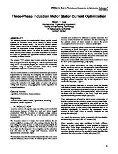
pneumatic actuators with their corresponding electromagnetic counterparts [7]. In particular, the aeronautic propulsion system can be improved, according to the More Electric Engine (MEE) philosophy, adopting an electric multiphase starter-generator embedded within the main aircraft engine [8]. This multiphase machine can be used as a motor for the starting and as generator during the flight. The key advantages of MEE are the removal of the hydraulic pumps and of the pneumatic starting system, and the optimization of the operation of the aircraft motor. In this paper, a quadruple three-phase induction motor drive is presented. In the machine, four three-phase stator windings with isolated neutral points, supplied independently by four two-level three-phase VSIs with separated dc sources, are arranged in the stator slots with a spatial shift of 15° electrical degrees. A schematic draw of the induction motor drive is illustrated in Fig. 1. The four VSIs can be supplied by a single dc source. The description of the quadruple threephase machine is not trivial, due to the magnetic coupling among the four three-phase windings. Therefore, a suitable machine model is derived by exploiting the potentialities of a specific space vector transformation. The proposed transformation can be considered a generalization of the one presented in [9] for a dual three-phase machine. A conventional Field Oriented Control (FOC) scheme is adopted for torque and rotor flux regulation, whereas the additional degrees of freedom of the multiphase drive are utilized for the management of the stator current sharing among the four three-phase stator windings. This feature allows a flexible power flow control to be obtained. A similar approach has been used in [10] for a dual three-phase induction machine. Note that, the fault operating conditions due to the stop of one or more inverters, can be simply accomplished with a particular choice of the stator current
A
C
Vdc
Vdc
12-Phase Vdc
Vdc
B
D
Fig. 1. Structure of the quadruple three-phase induction motor drive.
5173
sharing coefficients. The definition of the modulation strategy for the four three-phase VSIs is not so straightforward. Some solutions, based on Vector Space Decomposition, have been proposed in [9], [11], but they are valid for dual three-phase machines, only in particular operating conditions, and cannot be easily generalized. In this paper, the principle of the threephase decomposition of multiphase systems [12] is adopted. In this way, the well-known modulation strategies available for three-phase VSIs can be utilized. The effectiveness of the proposed quadruple three-phase induction motor drive, with stator current sharing capability, is verified by means of simulation results. II.
QUADRUPLE THREE-PHASE INDUCTION MACHINE
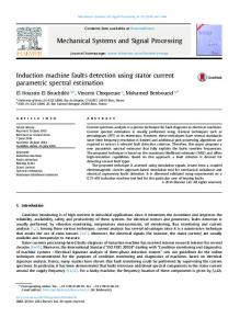
The quadruple three-phase induction machine is equipped with a squirrel cage rotor. Four three-phase windings, named A, B, C, and D, spatially shifted of 15° electrical degrees, are arranged in the stator slots. Each three-phase winding is separately star-connected. The positions of the magnetic axes of the twelve stator windings are illustrated in Fig. 2. A. Machine Model The machine model can be developed by starting from the analysis of the air gap magnetic field produced by the stator currents. Under the assumptions usually adopted for the analysis of ac machines, the spatial distribution of the stator magnetic field can be expressed, in a stator reference frame, in terms of three-phase stator current space vectors in the following compact form: hS (θ S ,t ) =
[(
[
+
[ ℜ [i
]
[( [( [(
)
] ]
)
)
(1)
]
where, NS is the number of series-connected conductors per phase, δ the air gap length, p the number of pairs of poles, ℜe the real part operator, KwSρ the ρ-th winding coefficient, θS a stationary angular coordinate in electrical radians whose origin is aligned with the magnetic axis of phase A1, whereas iSA , iSB , iSC , and iSD are the three-phase stator current space vectors (see Appendix). The symbol “*” identifies the complex conjugate quantities, and α=exp(jπ/12). Besides the fundamental component, (1) takes also into account the fifth, the seventh and the eleventh spatial harmonic of the stator magnetic field, and is expressed in terms of the instantaneous values of the stator currents. Note that the third and the ninth spatial harmonic are null, since they can be generated only by the zero-sequence components of the stator currents, which are zero owing to the star connection of each three-phase windings. The analysis of (1) suggests the definition of four new space vectors (multiple space vectors), whose direct and inverse transformations are illustrated in Appendix. The adopted multiple space vectors, specifically defined for
[
]
(2)
]
6 N S K wS11 − j 11θS e S11 e 11π δ p As can be seen, the stator current space vectors iS1 , iS 5 , iS 7 , and iS11 independently generate the first, the fifth, the seventh and the eleventh spatial harmonic components of the magnetic field in the air gap, respectively. In the following, sinusoidal distributed stator windings are assumed ( K wS 5 = K wS 7 = K wS11 = 0 ), and then, only the space vector iS1 produces air gap magnetic field. According to (2), and by means of tedious manipulations, it can be demonstrated that the mathematical model of the quadruple three-phase induction machine, expressed in terms of multiple space vectors (see (A5)-(A8) in Appendix) in a stationary reference frame, can be written as follows: dϕ (3) vS1 = RS iS1 + S1 , dt −
ϕS1 = LS1 iS1 + M1 iR1 , 0 = RR i R1 − j ω ϕR1 +
]
)
]
6 N S K wS 5 6 N S K wS 7 ℜ e iS 5 e − j 5 θ S − ℜ e iS 7 e − j 7 θ S − 5πδ p 7 πδ p
3 N S K wS1 ℜe iSA + α iSB + α 2 iSC + α 3 iSD e − j θS + 2πδ p
3 N S K wS 5 * * * * e − j 5 θS − ℜe iSA + α 5 iSB + α10 iSC + α15 iSD 10 π δ p 3 N S K wS 7 − ℜe iSA + α 7 iSB + α14 iSC + α 21 iSD e − j 7 θS − 14 π δ p 3 N S K wS11 * * * * − ℜe iSA + α11 iSB + α 22 iSC + α 9 iSD e − j11θS 22 π δ p +
quadruple three-phase machines, allow (1) to be rewritten as 6 N S K wS1 hS (θ S ,t ) = ℜe iS1 e − j θS + πδ p
(4)
d ϕR1 , dt
(5)
ϕR1 = M1 iS1 + LR1 iR1 ,
(6)
T = 6 p M1 iS1⋅ j iR1 ,
(7)
d iS 5 , (8) dt di (9) vS 7 = RS iS 7 + LSl 7 S 7 , dt di (10) vS 11 = RS iS 11 + LSl11 S11 , dt where v Sρ is the stator voltage vector in the αρ-βρ plane, iR1 , ϕS1 , ϕR1 are the rotor current vector, the stator flux vector, and rotor flux vector, respectively, in the α1-β1 plane, ω is the vS 5 = RS iS 5 + LSl 5
A2 B2
120°
C2
D1 C1
θS
B1
D2
15° A1
A3
B3
C3
D3
Fig. 2. Spatial position of the magnetic axes of the twelve stator windings.
5174
rotor speed in electrical radians, and T is the electromagnetic torque. Furthermore, LS1, LR1, and M1 are respectively the stator, the rotor, and the mutual inductances of α1-β1 plane, whereas LSl 5 , LSl 7 , and LSl11 are the stator leakage inductances of α5-β5, α7-β7, and α11-β11 planes. Four decoupled sets of equations have been found. The first one, i.e., (3)-(7), concerns the variables of the α1-β1 plane, namely the variables involved in the electromagnetic conversion process and then in torque and air-gap flux generation. The second one, the third one, and the fourth one, represented by (8), (9) and (10), are related to the variables of α5-β5, α7-β7, and α11-β11 planes (auxiliary variables), respectively. As can be seen, the control of torque and flux is achieved by acting on the space vector v S1 in the α1-β1 plane. However, also the space vectors v S 5 , v S 7 , and vS11 , in the other α-β planes, must be taken contemporarily under control, since they define the current sharing among the four three-phase stator windings, as demonstrated in Section III. III.
STATOR CURRENT SHARING CONTROL STRATEGY
In this Section, a strategy for the control of stator current sharing is presented. Since machine equations (3)-(7) are similar to those of a three-phase induction machine, a conventional FOC scheme can be adopted to control torque and rotor flux. Therefore, the stator current vector iS1 depends on the drive operating condition, i.e., torque reference, rotor flux reference, and rotor speed. On the contrary, the auxiliary stator current vectors iS 5 , iS 7 , and iS11 can be considered as degrees of freedom, and can be exploited in order to manage the current sharing among the four three-phase stator windings. According to (A5), the space vector iS1 of the stator current can be expressed as
[
]
1 (11) iSA + iSB α + iSC α 2 + iSD α 3 . 4 In order to minimize the magnitude of iSA , iSB , iSC , and iSD , the four contributions in the right hand of (11) must be in phase, leading to iSA = 4 K A iS1 , (12) iS 1 =
iSB = 4 K B iS1 α −1 ,
(13)
iSC = 4 K C iS1 α −2 ,
(14)
iSD = 4 K D iS1 α −3 ,
(15)
reference frame, give the instantaneous values of the auxiliary stator current vectors, according to the required current sharing. It should be noted that, in the particular case of KA=KB=KC=KD=1/4, i.e., balanced stator current sharing, all the auxiliary stator current vectors are null. It can be demonstrated that, when the degree of unbalance is small, the current sharing coefficients can be considered as instantaneous power sharing coefficients, with good accuracy. IV.
CONTROL SCHEME
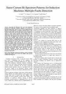
The block diagram of the control scheme ensuring a decoupled regulation of torque, rotor flux and stator current sharing is shown in Fig. 3. A. Torque and Rotor Flux Control According to the well-known FOC principle, torque and rotor flux control is achieved by acting on the q and d components of the stator current, in a synchronous reference frame S+ having the d axis aligned with the rotor flux ϕ R1 . The angle θ is the argument of the estimated rotor flux. The PI current regulators PI(c) and PI(d), which are adopted for the current tracking, calculate the d and q components of the reference voltage vector vS1,ref , respectively. The corresponding α-β components v S 1α ,ref , and v S 1β ,ref are obtained through a suitable rotation. B. Auxiliary Stator Current Control In order to achieve a zero steady-state tracking error, the control of the auxiliary stator current vectors must be implemented in two different synchronous reference frames, as explained in the following. Equation (18) shows that the current vector iS 7 is proportional to iS1 , and then, in steady-state conditions, iS 7 rotates synchronously with ϕ R1 . On the contrary, (17) and (19) emphasize that the current vectors iS 5 and iS11 are proportional to iS*1 , and then they rotate synchronously with ϕ*R1 . As a consequence, the PI current regulators for iS 7 , PI(g) and PI(h), are implemented in the reference frame S + synchronous with ϕ R1 , whereas the PI current regulators for iS 5 and iS11 , PI(e), PI(f), PI(i) and PI(l), are implemented in the reference frame S −, which is synchronous with ϕ*R1 (see Fig. 3). A diagram illustrating the three reference frames involved in the control strategy is shown in Fig. 4. Equation (17) and (19) can be rewritten in the reference frame S − synchronous to ϕ*R1 , whereas (18) can be rewritten in the reference frame S + synchronous to ϕ R1 . The resulting d-q equations are as follows:
where KA, KB, KC and KD are the current sharing coefficients, which must satisfy the following constraint: K A + K B + KC + K D = 1 . (16) Taking the transformations (A6)-(A8), and (12)-(15) into account, leads to the following relationships:
iS 5d = (K A − K C ) iS1d + (K B − K D ) iS1q ,
(20)
iS 5q = (K B − K D ) iS1d + (K C − K A ) iS1q ,
(21)
iS 7 d = (K A − K C ) iS1d + (K D − K B ) iS1q ,
(22)
iS 5 = (K A + j K B − K C − j K D ) iS*1 ,
iS 7 q = (K B − K D ) iS1d + (K A − K C ) iS1q ,
(23)
(17)
i S 7 = (K A + j K B − K C − j K D ) i S 1 ,
iS11d = (K A − K B + K C − K D ) iS1d ,
(24)
(18)
iS11q = (− K A + K B − K C + K D ) iS1q .
(25)
iS11 = (K A − K B + K C − K D ) iS*1 . (19) The relationships (17)-(19), valid in the stationary
The relationships (20)-(25) allow determining the reference values of the d-q components of the auxiliary stator
5175
ϕ R ,ref ωref
ϕR PI (a)
+ +
PI (b)
- ω
iS 1d ,ref -
iS 1d
PI (c)
+
iS 1q ,ref
+
PI (d)
-
iS 5 d ,ref -
KB KD
Eqs. (20)-(25)
iS 1d
PI (e)
vS 5α ,ref
vSBα ,ref
vS 5 q ,ref e − j θ vS 5β ,ref
vSBβ ,ref
vS 5 d ,ref
θ
iS 7 d PI (g)
+
PI (h)
vS 7 d ,ref
PWM (A)
vS 7β ,ref
vSC β ,ref
vS 11α ,ref
vSDα ,ref
vS 11q ,ref e − j θ vS 11β ,ref
vSDβ ,ref
e jθ
B
A 12-Phase
vSCα ,ref
vS 7 q ,ref
PWM (B)
Eqs. (26)-(29) vS 7 α ,ref
- iS 7 q
iS 11d ,ref -
PWM (C)
C
D
θ
iS 11d PI (i)
+
iS 11q ,ref
+
vSAβ ,ref
e jθ
- iS 5q
iS 7 q ,ref
+
iS 1q
vS 1β ,ref
vS 1q ,ref
θ
PI (f)
iS 7 d ,ref -
KC
vSAα ,ref
iS 1q
+
+
vS 1α ,ref
iS 5 d
iS 5 q ,ref
KA
vS 1d ,ref
PI (l)
vS 11d ,ref
- iS11q
PWM (D)
θ
Fig. 3. Block diagram of the control scheme.
contrary, the control principle of the inverters exploits the three-phase space vector representation of the three-phase quantities of each three-phase stator winding. The reference values of the three-phase stator voltage vectors, according with the inverse transformations (A9)(A12), can be obtained as follows:
β1 - β5 - β7 - β11 q1 – q7
q5 – q11
ϕR1
S+
d 1 – d7
θ θ α1 - α5 - α7 - α11
S−
d5 – d11
vSA = vS1 + vS* 5 + vS 7 + vS*11 ,
(26)
vSB = vS1 α 23 + vS* 5 α 5 + vS 7 α17 + vS*11 α11 ,
(27)
vSC = vS1 α 22 + vS* 5 α10 + vS 7 α10 + vS*11 α 22 ,
(28)
vSD = vS1 α 21 + vS* 5 α15 + vS 7 α 3 + vS*11 α 9 .
(29)
The well-known modulation strategies for three-phase VSIs (SVM or carrier-based PWM) can be adopted. Fig. 4. Diagram of the reference frames involved in the control strategy.
current vectors, and are used in the block diagram of Fig. 3. The PI current regulators PI(e)-PI(l), calculate the d and q components of the reference voltage vectors vS 5,ref , vS 7 ,ref , and v S11,ref . The corresponding α-β components are obtained through a suitable rotation of the vectors. C. Modulation Strategy of the Four Three-Phase Inverters The modulation strategy of the three-phase VSIs is based on the concept of three-phase decomposition. In other words, the control principle of the quadruple three-phase machine is based on the multiple space vector representation of all the twelve-phase quantities of the stator windings, whereas, on the
V.
SIMULATION RESULTS
To emphasize the effectiveness of the presented control scheme, some numerical simulations have been carried out by using Matlab Simulink. The parameters of the simulated induction machine are shown in Tab. I. The input DC voltage of the four three-phase VSIs is 215 V, whereas the switching period is 100 µs. The Space Vector PWM technique is implemented for the control of each three-phase VSI. The simulated operating condition is described in the following. The induction machine operates at constant speed (3000 rpm) and the rotor flux reference is maintained constant at the rated value (0.092 Wb). The torque reference has a
5176
Prated IS, rated VS,rated fS,rated p
= 100 = 113 = 150 = 200 = 2
kW Arms Vrms Hz (pairs)
= = = = =
5.7 6.1 2.67 2.71 2.59
mΩ mΩ mH mH mH
Torque (Nm)
50 0.5
0.6
0.7
0.8
Time (s)
0.9
1
1.1
0.9
1
1.1
S1q
(A)
150
Current i
100 50 0 0.4
0.5
0.6
0.7
0.8
Time (s)
Rotor flux (Wb)
Fig. 6. Waveform of the q component of the stator current vector i S1 . 0.1
0.05
0 0.4
0.5
0.6
0.7
0.8
0.9
Time (s)
1
1.1
20
iS5d
10
a)
,i
S5d S5q
(A)
Fig. 7. Waveform of the rotor flux magnitude.
Currents i
-10
(A)
0
20
-20 0.4
iS5q 0.5
0.6
0.7
0.8
0.9
Time (s)
1
1.1
iS7q
10
b)
LSl5 = 43.4 µH LSl7 = 41.7 µH LSl11 = 77.7 µH
0 -10 -20 0.4
iS7d 0.5
0.6
0.7
0.8
0.9
Time (s)
20
1
1.1
iS11d
10
c)
,i
S11d S11q
(A)
Currents i
,i
INDUCTION MACHINE PARAMETERS
RS RR LS1 LR1 M1
100
Fig. 5. Waveform of the electromagnetic torque.
CONCLUSION
In this paper, a motor drive for medium and high power applications, based on a quadruple three-phase induction machine, has been presented. Four two-level VSIs independently supply the three-phase stator windings. The machine model has been achieved by introducing a proper multiple space vector transformation, suitable for the particular stator winding arrangement. Exploiting the inherent degrees of freedom of the multiphase drive, a technique for current sharing management among the four three-phase stator windings has been presented. Since, the current sharing coefficients can be regarded as power sharing coefficients, the proposed control algorithm allows total motor power to be split among the four dc sources, in a flexible way, with three degrees of freedom. The three-phase decomposition method has been employed in order to establish the modulation strategy of the four three-phase VSIs. The stator current sharing capability of the proposed quadruple three-phase induction motor drive has been emphasized by means of simulation results. A system prototype is under development, TABLE I.
150
0 0.4
Currents i
VI.
200
S7d S7q
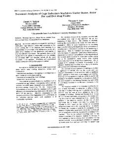
staircase waveform, with the following values: 160 Nm (rated value) from 0.4 s to 0.5 s, 80 Nm from 0.5 s to 0.9 s, and 120 Nm from 0.9 s to 1.1 s. The values of the current sharing coefficients are KA=KB=KC=KD=1/4 (balanced current sharing) from 0.4 s to 0.7 s, whereas, from 0.7 s to 1.1 s, they are KA=0.325, KB=0.275, KC=0.225, and KD=0.175. The simulation results are shown in Figs. 5-10. The waveform of the torque is illustrated in Fig. 5, whereas the behavior of the current iS1q is emphasized in Fig. 6. They confirm the good behavior of the torque control in balanced (t < 0.7 s) as well as unbalanced (t > 0.7 s) stator current sharing conditions. The high frequency torque ripple is due to the switching effects of the VSIs. As can be seen in Fig. 7, the rotor flux magnitude matches the reference value. The waveforms of the d-q components of the auxiliary stator currents are shown in Fig. 8. As expected, in balanced sharing condition all the auxiliary currents are zero. On the contrary, in unbalanced sharing condition, the auxiliary currents assume non-zero values, which depend on iS1d and iS1q, according to (20)-(25). The waveforms of the stator currents iSA1, iSB1, iSC1 and iSD1 (one for each three-phase stator winding) are shown in Fig. 9. They emphasize the stator current sharing capability of the proposed motor drive. In fact, in balanced sharing condition, the amplitudes of the currents are the same, whereas, in unbalanced sharing condition, the amplitudes are different, in agreement with the values of the sharing coefficients. The filtered values (low pass filter with time constant τ = 500 µs) of the instantaneous stator power of the four three-phase windings are illustrated in Fig. 10. These waveforms confirm that the current sharing coefficients can be regarded as power sharing coefficients.
0 -10 -20 0.4
iS11q 0.5
0.6
0.7
0.8
Time (s)
0.9
1
1.1
Fig. 8. Waveforms of the d-q components of the auxiliary stator currents.
and some experimental results will be presented in a future work. APPENDIX A. Three-Phase Space Vectors The behavior of the quadruple three-phase induction machine can be described in terms of four three-phase space vectors, one for each three-phase stator winding. The wellknown linear transformations are 2 (A1) x A = x A1 + x A2 α 8 + x A3 α16 , 3 2 (A2) xB = xB1 + xB 2 α 8 + x B 3 α16 , 3
[ [
5177
] ]
Current iSA1 (A)
200
a)
0 -100 -200 0.4
0.5
0.6
Current iSB1 (A)
200
0.7
0.8
0.9
Time (s)
1
1.1
b)
0 -100 0.5
0.6
0.7
0.8
0.9
Time (s)
1
1.1
Current iSC1 (A)
200
-100 0.5
0.6
0.7
0.8
0.9
Time (s)
1
1.1
Current iSD1 (A)
[1]
100
d)
0 -100 0.5
0.6
0.7
0.8
0.9
Time (s)
1
1.1
PSA, PSB, PSC, PSD (W)
Fig. 9. Waveforms of some stator currents. a) Current iSA1, b) current iSB1, c) current iSC1, and d) current iSD1. 15000
PSA
PSB
10000 5000
PSD
PSC 0.5
0.6
0.7
0.8
Time (s)
0.9
1
1.1
Fig. 10. Filtered values (time constant τ = 500 µs) of the instantaneous stator powers of the four three-phase windings.
[
]
(A3)
[
]
(A4)
xC =
2 xC1 + xC 2 α 8 + xC 3 α16 , 3
xD =
2 x D1 + xD 2 α 8 + xD 3 α16 . 3
The zero-sequence components are null due to the four isolated neutral points. B. Multiple Space Vectors A more useful model of the quadruple three-phase induction machine can be found by introducing four specific space vectors (multiple space vectors), which are defined according to the arrangement of the stator windings in the slots. The linear transformations are the following. 1 (A5) y1 = x A + x B α + xC α 2 + xD α 3 , 4 1 (A6) y5 = x*A + x*B α 5 + xC* α10 + x*D α15 , 4
* xC = y1 α 22 + y5* α10 + y7 α10 + y11 α 22 ,
(A11)
* xD = y1 α 21 + y5* α15 + y7 α 3 + y11 α9 .
(A12)
[
]
[
]
E. Levi, R. Bojoi, F. Profumo, H.A. Toliyat, S. Williamson, “Multiphase induction motor drives – a technology status review,” IET Electr. Power Appl., vol. 1, no. 4, pp. 489-516, July 2007. [2] E. Levi, “Multiphase electric machines for variable-speed applications,” IEEE Trans. on Ind. Electron., vol. 55, no. 5, pp. 1893-1909, May 2008. [3] H.S. Che, M.J. Duran, W.P. Hew, N.A. Rahim, E. Levi, M. Jones, “DClink voltage balancing of six-phase wind energy systems with seriesconnected machine-side converters and NPC grid-side converter,” Proc. of IECON 2012, pp. 3541-3546, 25-28 Oct. 2012, Montreal, QC, Canada. [4] A. Tessarolo, C. Bassi, “Stator harmonic currents in VSI-fed synchronous motors with multiple three-phase armature windings,” IEEE Trans. on Energy Conversion, vol. 25, no. 4, december 2010, pp. 974-982. [5] A. Tessarolo, G. Zocco, C. Tonello, “Design and testing of a 45-MW 100-Hz quadruple-star synchronous motor for a liquefied natural gas turbo-compressor drive,” IEEE Trans. on Ind. Applicat., vol. 47, no. 3, may/june 2011, pp. 1210-1219. [6] F. Scuiller, J.F. Charpentier, E. Semail, “Multi-star multi-phase winding for a high power naval propulsion machine with low ripple torques and high fault tolerant ability,” Proc. of Vehicle Power and Propulsion Conference, pp. 1-5, 1-3 Sept. 2010, Lille, France. [7] W. Cao, B.C. Mecrow, G.J. Atkinson, J.W. Bennett, D.J. Atkinson, “Overview of electric motor technologies used for More Electric Aircraft (MEA),“ IEEE Trans. on Ind. Electron., vol. 59, no. 9, september 2012, pp. 3523-3531. [8] A. Cavagnino, Zijian Li, A. Tenconi, S. Vaschetto, “Integrated generator for More Electric Engine: design and testing of a scaled size prototype,” Proc. of ECCE 2012, pp. 542-549, 15-20 Sept. 2012, Raleigh, NC, USA. [9] Y. Zhao, T.A. Lipo, “Space vector PWM control of dual three-phase induction machine using vector space decomposition,” IEEE Trans. on Ind. Applicat., vol. 31, no. 5, sept./opt. 1995, pp. 1100-1109. [10] G. Grandi, A. Tani, P. Sanjeevikumar, D. Ostojic, “Multi-phase multilevel AC motor drive based on four three-phase two-level inverters,” Proc. of SPEEDAM 2010, pp. 1768-1775, 14 - 16 June, 2010, Pisa, Italy. [11] K. Marouani, L. Baghli, D. Hadiouche, A. Kheloui, A. Rezzoug, “A new PWM strategy based on a 24-sector vector space decomposition for a six-phase VSI-fed dual stator induction motor,” IEEE Trans. on Ind. Electron., vol. 55, no. 5, may 2008, pp. 1910-1920. [12] G. Grandi, G. Serra, A. Tani, “Space vector modulation of nine-phase voltage source inverters based on three-phase decomposition,” Proc. of EPE 2007, pp. 1-12, 2-5 Sept. 2007, Aalborg, Denmark.
5178
Powered by TCPDF (www.tcpdf.org)
(A10)
REFERENCES
200
0 0.4
* xB = y1 α 23 + y5* α 5 + y7 α17 + y11 α11 ,
This work has been developed in the frame of PRIN2009 project “High Reliability Multi-Phase Electric Drives for the More Electric Aircraft” co-funded by the Italian Ministry of Research (MIUR).
c)
0
-200 0.4
(A9)
ACKNOWLEDGMENT
100
-200 0.4
] ]
* x A = y1 + y5* + y7 + y11 ,
100
-200 0.4
[ [
1 (A7) x A + x B α 7 + xC α14 + x D α 21 , 4 1 (A8) y11 = x*A + x*B α11 + xC* α 22 + x*D α 9 , 4 where the symbol “*” identifies the complex conjugate. The corresponding inverse transformations are y7 =
100