Nov 5, 1981 - Abstract-The steady-state and dynamic performance of a stator voltage-controlled currentsource inverter (CSI) induction motor drive are ...
219
IEEE TRANSACTIONS ON INDUSTRY APPLICATIONS, VOL. IA-18, NO. 3, MAY/JUNE 1982
The Stator Voltage-Controlled Current Source Inverter Induction Motor Drive MOHAMED A. ABBAS,
MEMBER, IEEE, AND
DONALD W. NOVOTNY,
Abstract-The steady-state and dynamic performance of a stator voltage-controlled current source inverter (CSI) induction motor drive are presented. Commutation effects are neglected and the analytical results are based on the fundamental component. A synchronously rotating reference frame linearized model in terms of a set of nondimensional parameters, based on the rotor transient time constant, is developed. It is shown that the control scheme is capable of stabilizing the drive over a region identical to the statically stable region of a conventional voltage-fed induction motor. A simple approximate expression for the drive dominant poles under no-load conditions and graphical representations of the drive dynamics under load conditions are presented. The effect of parameter variations on the drive dynamic response can be evaluated from these results. An analog simulation of the drive is developed, and the results confirm the small signal analysis of the drive system. In addition the steadystate results of the analog simulation are compared with experimental results, as well as with corresponding values obtained from a stator referred equivalent circuit. The comparison indicates good correspondence under load conditions and the limitation of applying the equivalent circuit for no-load conditions without proper recognition of the system losses.
INTRODUCTION THE ADVANTAGES of current source inverter (CSI) drives over voltage source inverter (VSI) drives (regeneration capability without the need for additional converters, simple commutation circuitry, and inherent short circuit current limiting) have increased the application of this drive in various industrial applications. However the instability of the drive, when it is operated as an open loop system, in most of its operational regions, has been a problem and requires a control scheme to stabilize the drive. A simple stator terminal voltage control that has been successfully adopted in industry is presented in this paper. This scheme eliminates the need for a tachometer to keep approximately constant volts per hertz and forces the system to behave statically as a voltage-driven induction motor as well as stabilizing the drive over the entire statically stable region. This paper presents a synchronously rotating reference frame linearized model for the drive in terms of the same Paper IPCSD 81-38, approved by the Industrial Drives Committee of the IEEE Industry Applications Society for presentation at the 1981 Industry Applications Society Annual Meeting, Philadelphia, PA, October 5-9. Manuscript released for publication November 5, 1981. M. A. Abbas is with Gould, Inc., Gould Laboratories, 40 Gould Center, Rolling Meadows, IL 60008. D. W. Novotny is with the Department of Electrical Engineering, University of Wisconsin-Madison, 1415 Johnson Drive, Madison, WI 53706.
SENIOR MEMBER, IEEE
nondimensional parameters that have been used in the analysis of VSI induction motor drives [1]-[3]. The use of these nondimensional parameters reduces the number of parameters needed to analyze the drive dynamics from twelve to six. All but two of the parameters are constant over a wide range of motor ratings. The result of this small signal analysis is very useful in determining the effect of the parameters on the drive dynamics. The drive is also simulated on an analog computer to verify the effectiveness of the control scheme and the validity of the linearized model. A comparison between the analytical and measured results in the steady state indicates the limitations of the stator referred equivalent circuit that was previously presented by the authors [4] . SYSTEM DESCRIPTION Fig. 1 shows a functional block diagram representing the drive. The three phase ac input is rectified by a phase-controlled six-pulse rectifier which could be replaced by a diode bridge rectifier if the input power factor is of major importance. In this case a chopper between the rectifier and the dc link has to be provided and the regeneration capability of the drive will be sacrificed. The inverter switches the dc link current from one phase to the other according to the firing sequence of the inverter semiconductor-controlled rectifiers (SCR's). The inverter frequency is determined by the output of the voltage to frequency converter (VFC). The motor terminal voltage is rectified by a six-diode bridge rectifier, filtered, and compared with the speed command. The output of the comparator determines the required change in the firing angle of the rectifier SCR's. If the drive voltage is chopper controlled, the comparator output signal will determine the duty cycle. In this analysis the following assumptions are utilized.
1) The motor is an ideal three-phase induction motor. 2) Thyristor voltage drop is neglected. 3) The commutation interval is assumed to be negligible compared to the conduction interval.
4) The voltage feedback loop is represented by a simple gain without any significant time delay.
5) The current regulator normally used to control the CSI
current is assumed to be an ideal regulator represented by a simple linear gain factor. 6) The analysis is based on the fundamental component
only.
0093-9994/82/0500-0219$00.75 © 1982 IEEE
220
IEEE TRANSACTIONS ON INDUSTRY APPLICATIONS. VOL. 2
3-ph.
Input
± F ig. I.
Peetif ier
-F Fioter
I TV )
IA-1S.
NO. 3,
~~~~Rs
MlAY/JUNE 19'2
XQe'
X,r
v
d
Xm
Rr/S
ier
Functional block diagram of the drive.
STEADY-STATE CHARACTERISTICS In a previous paper by the authors [41, a fundamental component stator referred equivalent circuit for the CSI fed induction machine was presented. This equivalent circuit accurately represents the transfer relations of an ideal CSI and provides a simple and powerful tool to analyze the drive. Fig. 2 shows this equivalent circuit and its relation to the
command and feedback signals. The variable capacitor is always in series resonance with the motor reactance, and thus, represents the capability of the inverter to supply the reactive power required by the motor. It has been reported [41 -[61 that an open loop voltageexcited CSI induction motor drive has a torque speed characteristic that combines the properties of both cuLrrent- and voltage-excited induction motors. Fig. 3 illustrates the steadystate torque-speed characteristic for such an open loop drive. The portion of the characteristic at high speed is similar to the high speed characteristic of a constant current driven induction motor while the rest of the characteristic is similar to that of a voltage-driven induction motor. The equivalent circuit shown in Fig. 2 (without the feedback loop) provides a simple explanation of this unusual characteristic. The initial torque peak, at very small slip, is a result of the large motor current caused by the inverter equivalent capacitive reactance canceling the large motor inductive reactance. At zero slip, only the motor stator resistance and dc link resistance limit the motor current. The torque imiinimumi corresponds to minimum motor current which exists for a slip equal to (Rr/Xr). For slip values greater than this value the motor current again increases, leading to the second torque peak. Implementing the voltage control loop regulates the inotor voltage and overcomes the effects of the inverter equivalent capacitive reactance. The resulting steady-state torque-speed characteristic is clearly the samie as for any machine driven from a fixed voltage source. Thie variable motor voltage resulting from the equivalent series capacitance of the CSI can be viewed as a motivation for implementing the voltage control loop, although the loop also leads to important dynamic performance improvements as will be shown.
DYNAMIC MODEL To facilitate development of a linearized model, the system is represented in a synchronously rotating reference frame. Selecting the reference angle of the rotating frame such that
Speed
co mmand Fundamental component referred to stator equivalent circuit.
fig. 2.
'A
t/
TO RQUE (PU)
Fig. 3.
Torque-speed characteristic for voltage excited CSI with and without voltage feedback loop.
the inverter output current is entirely in the -y-axis yields the
simplest model since the 6-axis stator current is identically zero. However the 6-axis induced voltage must be evaluated since it represents a portion of the motor terminal voltage
and thus enters the system equations via the voltage feedback loop. Physically the 6-axis induced voltage represents the unconstrained voltage which exists on the open motor phase during each conduction mode of the inverter. In the steady state it is the quadrature comuponent of the motor voltage represented by the equivalent inverter capacitive reactance in Fig. 2.
221
ABBAS AND NOVOTNY: INDUCTION MOTOR DRIVE
The inclusion of the V6 , in the model does not increase the order of the system; the CSI current constraint still reduced the system to a fourth order system. The derivation of the equations is given in the Appendix; the resulting matrix equation is R
akvc
0
0
LTLi
-Wm ~0
O
Rr
-OLr
OLr
R,
0
0
O
O
0
Linearized Model The system equations (1) are nonlinear differential equations, and in order to apply the conventional techniques of linear control system theory, they will be linearized about a steady-state operating point. If the speed command or shaft load is allowed to perturb from their steady-state values, corresponding perturbations will take place in the system variables. After perturbation the forcing functions and state variables become
i
it i'6r
0
r
_X#_
Vsmax
+
ELM M Lr +
0
0
0 0
0
0
[ys]
Lr
0
ilYr
-J 0 0
16
i5r
=I6ro±a+
C
=
(1)
L+
-2akc
33Vsmax smax o
2akc
V-SOLs M±+ 3Vs max o V0soM
smax o
0
Lr 0
0 Lr
0
0
0
(V7soRs
+
oLsL5V6so)-R
0 0 -I
2akc
-2akc
nI6 ro
sm ax
F=
o
'soLr
LrI
0
0
Rr
nMI,so
0
rbsO(LS7Yso ±MIyro) ro
-(LrIyro + MI7yso)
-MI6roV-ysol
±MIro ° °
1
I'Aiys /izyr, Ai6r, A U = [,AVC,' ACO A TLI T.
XF =
r]
M V750 + coM ra
3 V~~a oM06SO3 Vs~x
-WsoLr
-2akc
(3)
VysoM 0
Rr
0
3V
(2)
=r= 'ro + LAr.
where
2akc
3 Vs max o M
iyr =Iyro+Aiyr TL = TLO + ATL
= GXi + Fii
=LS +a2Ld.
2akc
wo + Aw,
Vco + IAvc
rJ
n4
where R =RS+ a2Rd, L
68r,
Vc
Substituting (2) into (A6), eliminating the steady-state solution and assuming small perturbations, such that the product of the perturbed variables can be neglected, the system linearized model becomes
r
0-
AVsmax,
Vsmax o +
0
-LrI ro MISO + LrLyro 0
IEEE TRANSACTIONS ON INDUSTRY APPLICATIONS, VOL. lIA-18, NO. 3. MAYIJUNE 1982
Nondimnensional Paranieters The linearized system equationls show that 1 2 parameters and variables (RS, Ls, Rd. Ld, R, L..Mw, w . J, i12 and Vco) are required to describe the drive. Using the nondimensional parameters which have proven very successful in reducing the number of parameters and variables required to describe the voltage source driven induction inachine [ 11, [21, [71, [8] reduces the number of parameters to only six. In addition most of these parameters are nearly constant [2] for a wide range of machine ratings, which allows generalization of the results. The nondimensional parameters that have been used in voltage source driven induction machines are based on the rotor transient time constant and summarized below: *
Rs
Tr?
=-r
Rr
M2
1-
*
ratio of transient tinme constants
-
Ts'
leakage parameter
-
LsLr
nondimensional stator frequency Tr'
IlToTr'
ratio of transient and electrochemical time constants
where
L1
rotor transient time constant
LI Rs Rs
stator transient time constant
LLs
TS Tm
L2 Rr
Lr Ry
=-
under no-load conditions.
nIo
/
a
x=-- +-
/
2 21\
a
2
4KaLrw-
2a2o ±(2) LS(avao+~
(5)
Since Lr/LS can be made equal to unity by an appropriate choice of turn ratio and a2a 2 < 02. (5) can be approxinmated
electromechanical tiIne constant
S
[XJ-AI =0O
No-Load Conzditionz The eigenvalue loci are very simple for zero load since at zero slip frequency the fourth order characteristic eqLuationi can be factored into two second order equations; one of theim yields two' real eigenvalues independent of K while the other yields the following expression for the dominant eigenval Ues
Jwso T171 X-T,'p nondimensional eigenvalue L
DYNAMIC CHARACTERISTICS The nondimensional parameters can be used to derive the system nondimensional state matrix A. Since the eigenvalues of the state matrix A are the poles of the system, they determine the local asymptotic stability of the drive. Solving the system characteristic equation
the drive will be locally asymptotic stable if, and only if, all of the eigenvalues hiave strictly negative real parts. Fig. 4 shows typical eigenvalue loci for low and hiigh speed with K as a varying parameter and both inverter frequency and slip frequency as constants.
ciso = xso Tr' nondimensional slip frequency
Tr
The dynamics of the drive can be described in termiis of am, Guil, 1. co0. WSO, and K. Note that in contrast to the CSI case, in the VSI driveni induction mlotor inicluding the dc link filter increases the order of the system by adding one more state variable, while the symlmetr-y of the mlotor voltage equations is retained.
det
too0- WoTr'
T='-
L 4L
as
total leakage inductance
P =d/dt. Using these parameters, voltage source-fed induction motor dynamics can be conmpletely represented by the five parameters a, a, C, w,3, and k, instead of the ten conventional parameters Rs, Rr, Ls, L,, M, J, n, V, c, and cos. In the system shown in Fig. I there are two additional parameters describing the dc filter and they are always combined with the stator paraineters. Therefore the system order has not changed, but one additional nondimensional parameter and one modified paramieter are needed to describe the dynamics of the drive in terms of six nondimensional paranmeters instead of the twelve conventional parameters. Defining cra,l L
x whiich
-can
I 2
N
ai -4ukr
be further
a
xn.t-2
a
+
2
1
(6)
approximated
to
a
for K
lmilftfi4u .;u MIMI t[Rit"mtn-m
1Vi,4 4M If liftfla
I
18000
I
;T
RPM
11
-
178.57 FNM
+100%
1
-10%
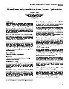
Fig. 7. Analog traces for 60 Hz CSI excitation, free acceleration, and rated torque step, and -10 percent rated load torque step (inertia = 0.2641 kg-m2).
A study of the effect of the dc link inductance on the Analog Simulation dynamics of the drive under load conditions has shown that The inverter representation is based on the simplified increasing the dc link inductance moves the dominant eigen- simulation of a CSI that was developed by Bose and Lipo [9] values very slightly to the right, except for large machines where all commutation details are omitted. The induction (large K) and high speed where they move slightly to the left. motor is represented in the stationary (fixed in the stator) However the influence is a second order effect and is normally reference frame [101, where the number of amplifiers renot significant. quired to transform the variables is minimum. The details ANALOG SIMULATION AND EXPERIMENTAL RESULTS of the induction machine analog computer representation To obtain a second evaluation of the effect of the voltage are given in [10] while the representation of the inverter and feedback on the drive dynamic performance and the accuracy dc link is given in [9]. The simulation of the feedback loop of the equivalent circuit of Fig. 2, the drive was simulated on was carried out in exactly the same way as in the small signal analysis of the Appendix. Figs. 7 and 8 are samples of the an analog computer and experimental measurements were analog traces at 60 Hz inverter frequency. In this simulation a terminal performed on a commercial CSI drive with stator the inverter frequency was adjusted for 60 Hz and the refervoltage feedback loop.
226
IEEE TRANSACTIONS ON INDUSTRY APPLICATIONS, VOL. IA-18, NO. 3, MAY/JUNE 1982 "1 - CRz 1Xa Ir -.-
.X s e
-w
V
V
-1800 RPM
-71.43 NM
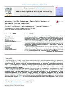
Fig. 8.
Analog traces for 60 Hz CSI excitation and full load steadystate condition.
ence voltage was suddenly applied to the drive. In Fig. 7 the
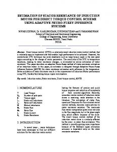
laboratory. The drive is rated at 10 hp and uses a stator voltage feedback loop. The input coverter of the drive is a six-diode bridge rectifier. Therefore a chopper is used to control the dc link voltage. Figs. 9(a) and (b) shows photographs of stator phase voltage, current, and inverter dc voltage for 60 Hz at rated absolute slip.
current, stator phase voltage and current, rotor speed, and electromagnetic torque at rated load.
Comparison Between the Results Both steady-state and dynamic results are compared. For the steady state a comparison between the analog simulation, experimental tests, and the application of the equivalent circuit of Fig. 2 is presented. A comparison of the dynamic response for both analog simulation and small signal analysis based on the dominant transient mode is presented.
machine was allowed to accelerate freely to the steady-state no-load speed, then a fully load torque was applied and after reaching steady state, 10 percent of the load torque was suddenly removed. This trace shows clearly how the drive behaves similar to the conventionally voltage-fed induction machine. Fig. 8 shows traces of the inverter dc voltage, dc link
Experimental Results The experimental results were obtained from a commercial CSI induction motor drive at the University of Wisconsin drive
227
ABBAS AND NOVOTNY: INDUCTION MOTOR DRIVE TABLE II DOMINANT POLE FREQUENCY OF OSCILLATION Frequency of oscillation (Hz) _-
____________
___
No load K
0.4375 1.4 2.573
Fig. 9. Experimental waveforms for 60 Hz rated absolute slip operation. (a) 100 V/cm, 20 A/cm, 5 ms/cm. Inverter output phase voltage and current. (b) 100 V/cm. 2 ms/cm. Inverter input dc voltage. TABLE I
COMPARISON OF THE STEADY-STATE RESULTS AT 60 Hz Load
Condition
Variable speed (rpm)
No Load
Vph (trms) VI
Iph
(rns)
Idc
speed (rpm)
Vph VI Full Load
I
(rms)
ph (rts)
Idc
Tee
Equivalent Circuit Calculations 1800
Analog Simulation Result 1800
Test Measurement
1797
5.8 11.23
127.3 44 12.08
122.4 184.0
14.4
14.8
10
1764 127 232.8
1764 129.6
128.05
19.37 24.84 29.37
268.0
21.3 26.25 27.9
9
1764 122.4 272
17.8 21
22.5
Analog simulation 1.94 3.5
5.0
,-------_
_-_--____-_-__-_--__-__-__
Rated absolute slip
Small
Analog simulation
2. 3.65
3.5 5.8 7.0
signal
4.97
Small
signal 3.37 5.47 6.78
absolute slip. The table shows that the dominant poles oscillate with approximately the same frequency, which verifies the correspondence of the linearized model with the analog simulation and illustrates the effectiveness of the voltage feedback loop to expand the dynamically stable region of the drive to cover the entire statically stable region. ADEQUACY OF THE MODEL Although the results clearly indicate the importance of the leakage parameter in determining the dynamics of the drive under both no-load and full-load conditions, it has to be recognized that other factors that have not been considered in this analysis may also contribute significantly and have to be taken into account in order to make an optimum design. In [11] equations which determine the approximate rating of the inverter components are given. These expressions indicate that for the same commutation capacitance, an increase in the leakage parameter will increase the voltage rating of all inverter components. These voltage ratings can be reduced by increasing the commutation capacitance, and consequently, increasing the commutation time (requiring more time for the current to transfer from phase to phase). However this capacitance increase will decrease the- maximum inverter output frequency. Therefore a compromise must be made or additional circuitry (a voltage clamping circuit) must be added. In this model the effect of commutation was neglected. This approximation is acceptable for low speed drives where the commutation period is small compared to 1/6f. However at high speed the ratio of the commutation period to 1/6f increases and the time delay caused by this commutation process cannot be neglected. In addition, increasing the commutation capacitor to reduce the voltage ratings of the inverter components, as suggested above, will further increase the commutation time delay. As is well-known in control systems, a time delay reduces the system damping and may cause instability. Accordingly, to make this model accurate for any range of frequency, the commutation process has to be represented. Work is under way at the University of Wisconsin-Madison to carry out a more complete analysis.
Steady-State Comparison Comparing the analog simulation traces with experimental results indicates that the main difference is the voltage spikes imposed on the phase voltage in the analog simulation trace. The magnitude is much higher than the measured values as a result of assuming ideal switches and the absence of a voltage clamping circuit in the analog simulation. Table I summarizes the steady-state results obtained from the equivalent circuit, analog simulation, and test measurements. The results show very good correlation for load conditions, while the correlation is poor for no-load conditions, especially for the inverter voltage. The reason is the dependence of the inverter voltage on the machine power factor. In both the equivalent circuit and the analog simulation, it is assumed that the induction machine is an ideal machine. For example, there are no losses other than the stator copper losses at no-load, which is not true in practical machines. In addition, the inverter is represented by ideal switches. Therefore all voltage drops across the inverter SCR's and commutation circuits are neglected. The difference between the calculated value and the analog simulation results is due CONCLUSION to considering only the fundamental component in developThe analysis, analog simulation, and experimental results ing the equivalent circuit plus the reflection of the voltage in this paper demonstrate the effectiveness of stator voltage spikes on the dc side in the analog simulation. feedback control of a CSI-fed induction machine in producing a stable variable speed motor drive. In particular the results Dynamic Response Comparison show the following. Table II presents the dominant pole frequency of oscillation for both analog simulation and small analysis as a func1) The drive steady-state characteristics are identical to a voltage-fed machine, and the system is dynamically tion of the nondimensional gain K at no-load and at rated
IEEE TRANSACTIONS ON IND)USTRY APPLICATIONS. VOL. IA-18, NO. 3. MAY/JUNE 1982
2 Q2
stable for motor operation throughlout the statically stable region. 2) There is excellent correspondence between the small signal model and the more complete analog simulation. This confirnms that the small signal analysis is a correct representation of the normal idealized machine model, and except for higher order effects (saturation, deep bar effect, inverter losses, etc.). it can be used to study system performance with confidence. 3) Experimental confirmation of the steady-state results of the analog simulation and the equivalent circuit shows excellent correspondence except at light load, where inverter and machine losses are dominant. 4) The most important results of the smiall signal analysis are as follows. a) Worst damping occurs at no-load, where for the typical case of KA > o/4, the dominant eigenvalues are given by the simple closed form expression: x
a =
1)
±
JN/go,
L[-- L+
K`/
(real time)
5) The high operating frequency instability often reported in systems of this type is not predicted by the model of the paper. There is reason to believe this instability is associated with commutation delay which is neglected in the present analysis. Subscripts c
d 1 L m 0
r s
,yr, 6r ys, S6s
Variables a c
Command. DC link quantity. Leakage. Load. Stator to rotor mutual. Steady-state quantity. Rotor quantity. Stator quantity. Rotor variables in synchronous frame. Stator variables in synchronous frame.
Error signal.
Instantaneous.
i 1 Ai
dc component, and perturbation
current. J Rotor monment of inertia. Input rectifier gain. k Inductance. L M Stator to rotor mutual inductance. Number of pole pairs. n7 Referred to stator per phase resistance. R S Per Lunit slip. T. AT Torque and perturbation torque. v, V, A.v Instantaneous, dc cotmiponent, and perturbation voltage. w, Au Instantaneous and perturbation speed. APPENDIX DERIVATION OF THE DRIVE EQUATIONS The induction motor can be described in a rotating reference frame in matrix form [1 as
synclhronously
[vs-J .
Thus machines with small a have poor damping, and there is a conflict between the need for low leakage to minimize voltage spikes and high a to improve damping. Note that the damping is essentially independent of operating frequency, stator resistance, and dc link inductance and resistance. b) Under full-load conditions, the dominant eigenvalues exhibit performance similar to a voltage-fed machine. There is a specific frequency at whiich mrlinimum damping exists which can be estimated from Figs. 5 and 6. In general, larger values of a and smaller values of a yield better damping. The influence of dc link inductance depends on machine rating and operating frequency but is typically a small effect.
NOMENCLATURE
e
u5^,
±Lsp pLs NP
Mp
MP
Rs Mpsp
Rr +LrP
Mp
(-)-Ar)Lr
-WM
Mp
-(W
cr)Lr
Rr LrP
FieYs
Ibis
(Al)
Iiyr
L'brJ
and the torque balance equation is
TL
+J
nidt=r-
d
nM(i6s
yrl-ys i r).
(A2)
A proper choice of the initial reference angle allows all the stator current to be placed in one axis which yields the simplist representation of the inverter current constraint and eliminates the 6-axis equation except for the effect of v6, on the feedback equations. From Fig. 10 the output voltage of the input rectifier can be written as
Vd
=
ke
=
k(vc- CVs m ax) =(Rd +LdP)id + VI1
(A3)
Using the inverter ratio
UVs = id VI iy s
_ a-r/3j
yields Inverter ratio. DC to ac rectifier ratio.
v-=av1 =ak(vc-cvsmax) -a2(Rd ±Ldp)iYs.
(A4)
229
ABBAS AND NOVOTNY: INDUCTION MOTOR DRIVE
Vc
Rect. Fig. 10. Block diagram of closed loop system.
The amplitude of the phase voltage is related to v s by the relation Vsmax =
(A5)
V6s2).
3
and
ay,
substituting (A4) and (AS) in (Al), eliminating the 6-axis equation, combining the result with equation (A2) and rearranging yields
akvcl L
-RS +
Rr
=
coM
O
L TL J
02Rd -coM
ackV
+
+
CLr Rr O
L
-WL_ O
0 ° °
[i
i;r is r
W,rris r
-COAMty, + L r Iyr) -nMis r ilyS 0
Lr
0
0
Lr
0
0
0
nJ n
M 0
_0
[1
Pi'
LZ:rr
[8]
[9]
[11]
(_Vz2 + -,S2
0
[7]
[10]
OJ _WOrJ
+La2Ld M Ls
[6] N. Sato, M. Ishida, and N. Sawaki, "Some characteristics of
.
induction motor driven by current source inverter," in Conf. Rec. IEEE/IA Int. Semiconductor Power Converter 1977, pp. 477-482. A. R. Miles and D. W. Novotny, "TransfeF functions of the slipcontrolled induction machine," IEEE Trans. Ind. Appl, vol. IA-15, pp. 54-62, Jan./Feb. 1979. D. W. Novotny, "Steady state performance of inverter driven induction machines by means of time domain complex variables," IEEE Trans. Power App. Syst., vol. PAS-95, pp. 927-935, May/ June 1976. B. Bose and T. A. Lipo, "Control and simulation of a current-fed linear induction machine," IEEE Trans. Ind. Appl., vol. IA-15, pp. 591-600, Nov./Dec. 1979. P. C. Krause and C. H. Thomas, "Simulation of symmetrical induction machinery," IEEE Trans. Power App. Syst., vol. PAS84, pp. 1038-1053, Nov. 1965. M. Showleh, W. A. Maslowski, and V. Stefanovic; "An exact modeling and design of current source inverters," in Conf. Rec. 1979, 14th Annu. Meet. IEEE Ind. Appl. Soc., pp. 439-459.
Mohamned A. Abbas (S'79-M'80) received the B.E.E. degree from the Higher Industrial Institute of Cairo, Egypt, in 1964, the M.S.E.E. degree from the Polytechnic Institute of New York in 1976, and the Ph.D. degree in electrical engineering from the University of WisconsinMadison in 1980. He joined the power electronics group of Corporate Research and Development, Gould Inc., in Rolling Meadows, IL in 1980.
(A6)
ACKNOWLEDGMENT The authors wish to express their appreciation to the Graham Transmissions Company of Menomonee Fall, WI, for providing the current source inverter drive used in the experimental part of this research.
Donald W. Novotny (M'62-SM'77) received the B.S. and ifrom the Illinois Institute of Technology, Chicago, in 1956 and 1957, and the Ph.D. degree from the University of Wisconsin, Madison, in M.S.
[1] D. W. Novotny and J. H. Wouterse, "Induction machine transfer functions and dynamic response by means of complex time variables," IEEE Trans. Power App. Syst., vol. PAS-95, pp. 13251335, July/Aug. 1976. [2] R. Stern and D. W. Novotny, "A simplified approach to the determination of induction machine dynamic response," IEEE Trans. Power App. Syst., vol. PAS-97, pp. 1430-1439, July/Aug. 1978. [3] A. R. Miles, "Slip and volts/Hz control of induction machines," Ph.D dissertation, University of Wisconsin, Madison, 1978. [4] M. Abbas and D. W. Novotny, "Stator referred equivalent circuits for inverter driven electric machines," in Conf. Rec. 1978, 13th Annu. Meet. IEEE Ind. Appl. Soc., pp. 828-835. [5] N. Sawaki and N. Sato, "Steady state and stability analysis of induction motor driven by current source inverter," IEEE Trans. Ind. Appl., vol. IA-13, pp. 244-253, May/June 1977.
in
electrical
engineering
1961.
Since 1961 he has been at
REFERENCES
degrees
the
University
a
member of the faculty
of Wisconsin-Madison
where
he is currently Professor and Director of the Wisconsin Electric Machines and Power Electronics Consortium (WEMPEC). He served as Chairman of the Electrical and Computer Engineering Department from 1976 to 1980 and as an Associate Director of the University-Industry Research Program from 1972 to 1974, and from 1980 to the present. He has been active as a consultant to many organizations including Marathon Electric Company, Borg Warner Corporation, Barber Coleman Company, Otis Elevator Corporation, Allen Bradley Company, Eaton Corporation, and the Wisconsin Department of Natural Resources. He has also been a Visiting Professor at Montana State University and the Technical University of Eindhoven, Eindhoven, Netherlands and a Fulbright Lecturer at the University of Ghent, Ghent, Belgium. His teaching and research interests include electric machines, variable frequency drive systems, and power electronic control of industrial systems. Dr. Novotny is a member of the American Society for Engineering Education, Sigma Xi, Eta Kappa Nu, and Tau Beta Pi, and is a Registered Professional Engineer in the State of Wisconsin.