Dynamically Scheduling the Trace Produced During Program Execution into VLIW Instructions Alberto Ferreira de Souza 1 and Peter Rounce Department of Computer Science University College London Gower Street, London WC1E 6BT - UK
[email protected],
[email protected]
Abstract VLIW machines possibly provide the most direct way to exploit instruction level parallelism; however, they cannot be used to emulate current general-purpose instruction set architectures. Programs scheduled for a particular implementation of a VLIW model cannot be guaranteed to be binary compatible with other implementations of the same machine model with different number of functional-units. This paper describes an architecture, named dynamically trace scheduled VLIW (DTSVLIW), which can be used to implement machines that execute code of current RISC or CISC instruction set architectures in a VLIW fashion, with backward code compatibility. Some preliminary performance measurements of the DTSVLIW, obtained with an execution-driven simulator running the SPECint95 benchmark suite, are also presented.
1. Introduction Very Long Instruction Word (VLIW) machines can execute several scalar operations in a single clock cycle [1]. They have long instructions (hundreds to thousands of bits), with fields to control each of their many functional units. These long instructions are fetched from memory, one per processor clock cycle, and issued to functional units that operate in parallel. In VLIW machines, the compiler has complete responsibility for creating a package of operations that can be simultaneously issued. The hardware does not dynamically make any decisions about multiple operation issue, and thus the VLIW hardware is simple and fast. However, the assumptions built into the object code by the compiler about this hardware prevent object code compatibility between different implementations of the same VLIW instruction set architecture (ISA). VLIW processors with different levels of parallelism require recompilation of the source code. This problem, known as the VLIW object code compatibility problem, has made VLIW machines of limited commercial interest [7]. Furthermore, it is not
1
Sponsored by CAPES (Brazilian Government Agency).
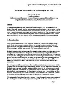
possible to implement current RISC or CISC generalpurpose machines as a standard VLIW architecture. This paper presents an architecture, implementing a concept first proposed by Nair and Hopkins [9], that has the potential to overcome the VLIW drawbacks and preserve its advantages. This architecture, named dynamically trace scheduled VLIW (DTSVLIW) [2], has two execution engines: the Scheduler Engine and the VLIW Engine, and two instruction caches: the Instruction Cache and the VLIW Cache. A block diagram of the DTSVLIW architecture is shown in Figure 1. The Scheduler Engine fetches instructions from the Instruction Cache and executes them singly the first time using simple pipelined hardware. In addition, it dynamically schedules the trace produced during execution into VLIW instructions, placing them as blocks of VLIW instructions in the VLIW Cache. If the same code is executed again, it is fetched by the VLIW Engine from this cache and executed in VLIW fashion. In a DTSVLIW machine, the Scheduler Engine provides for object-code compatibility, and the VLIW Engine provides VLIW performance and simplicity. In order to evaluate the DTSVLIW architecture, a parametric simulator has been implemented and executiondriven simulation performed using the SPEC95 benchmark suite. Experimental results presented here show that the DTSVLIW executes VLIW instructions on almost 90% of the cycles on average and achieves significant Instruction Level Parallelism (ILP). This paper is organised as follows. In the next section, related work is discussed. The DTSVLIW machine is fully described in Section 3. In Section 4, the experimental methodology and the results of the experiments carried out to evaluate the DTSVLIW architecture are presented. Section 5 contains the conclusions and proposals for future work.
2. Related Work Existing techniques to get over the VLIW code compatibility problem can be divided into software [3, 4, 5, 6] and hardware [7, 8, 9] techniques. The simplest software technique is off-line recompilation of source programs. The drawbacks of this approach are that it is awkward to use
and the source code may not always be available. Binary translation [3] is a variant of this technique that can be performed without the source code, but is also awkward to use. Alternatively, interpreters can be used to emulate different architectures at run-time; however, this approach usually suffers from poor performance. Binary translation and emulation can be combined [4]. Dynamic Rescheduling, proposed by Conte and Sathaye [5], is another software technique. When a program is invoked in a system that implements dynamic rescheduling, the operating system reschedules the first program page and saves it in a new page, which is compatible with the system hardware. This process is repeated each time a new page fault occurs. Ebcioglu and Altman [6], with their DAISY machine, extended the concept of dynamic rescheduling to dynamic compilation, in order to use a generic ISA. Dynamic rescheduling and dynamic compilation rely on the ability of the operating system to translate code rapidly and on the reusability of this code. However, since it is implemented in software, the cost of the translation is high. Rau [7] presented a new type of VLIW machine, named dynamically scheduled VLIW (DSVLIW), which tackles the software compatibility problem at the hardware level. A DSVLIW machine splits each instruction member of a long instruction (the term used in this paper to refer to a VLIW instruction) into two components: phase1 and phase2. The phase1 component is the original instruction with its destination renamed, while phase2 is a copy instruction copying the phase2 result to the original destination. Both instruction components can be issued simultaneously to functional units’ reservation stations. Once execution of phase1 finishes, the reservation station with phase2 receives the result. The execution of each original instruction is completed after the execution of phase2, which can be done in just one more cycle. Despite the ability to implement a family of VLIW machines with different functional units’ latency and the same ISA, the DSVLIW concept cannot be used to implement an existent sequential ISA. In addition, it requires dynamic scheduling hardware in the main data path of the machine, which can have a negative effect on the clock period. Franklin and Smotherman [8] proposed the use of a fill unit [10] to compact a dynamic stream of scalar instructions into long instructions: the fill unit accepts decoded instructions from the machine decoder, compacts them into a long instruction, and saves the long instruction in the shadow cache. At the same time, the fill unit sends the long instruction to the functional units for execution. Fetch accesses that hit in the shadow cache provide long instructions directly to the functional units. The fill unit does not rename registers, resulting in a reduction in the capacity to deal with output data dependencies, and works within a window of only one long instruction. For these reasons it cannot exploit ILP extensively. Nair and Hopkins [9] suggested a VLIW based architecture named DIF (Dynamic Instruction Formatting), which is an improvement of the Franklin and Smotherman proposal. The DIF architecture incorporates two engines: the VLIW Engine and the primary engine. The latter is a
simple processor, less aggressive in exploiting parallelism, which executes instructions when first fetched. Simultaneously with the execution of a code sequence, this engine reformats the code, generating groups of long instructions as opposed to a single long instruction. Groups are saved in a special cache – the DIF Cache. Following accesses to the same sequence will hit the DIF Cache and the long instructions fetched will be executed for the VLIW Engine. The DTSVLIW architecture is similar to the DIF and was developed shortly after it, but without knowledge of its existence. This was beneficial because permitted a significantly different implementation. The differences between then are detailed in Section 3.12. The DTSVLIW long instruction resembles the tree instruction introduced by Nakatani and Ebcioglu [11]. However, the DTSVLIW long instruction is particularly suitable for a VLIW machine that executes scheduled trace code, while the tree instruction was proposed to hold VLIW code produced by VLIW compilers. The DTSVLIW long instruction can be viewed as a special case of the tree instruction, although it has not been derived from this approach. A core scheduling operation performed by the DTSVLIW, the move up operation (see Section 3.2), is similar to the move-op with renaming operation of the enhanced pipeline percolation scheduling technique [11]. However, their application is different, reflecting their From Memory
Instruction Cache
VLIW Cache Fetch Unit
Scheduler Engine
To/From Memory
Primary Processor
VLIW Engine
Scheduler Unit Scheduling List
Data Cache
different purposes: move-op was designed for scheduling during compile time, and move up was designed for scheduling during execution time. The move-op operation is applied in a sequential fashion by the compiler; in contrast, the move up operation is applied here in a pipelined parallel fashion by the hardware. Figure 1: The Dynamically Trace Scheduled VLIW Machine.
3. A DTSVLIW Machine In this section, an implementation of the DTSVLIW architecture is presented. This implementation executes SPARC Version 7 ISA [12] code.
3.1 The Scheduler Engine The Scheduler Engine is composed of the Primary Processor plus the Scheduler Unit (Figure 1). The Primary Processor is a simple pipelined processor that is capable of executing all instructions defined in the SPARC ISA. When
an instruction completes execution, the Primary Processor sends it to the Scheduler Unit. The Scheduler Unit implements in hardware a simplified version of the First Come First Served (FCFS) algorithm, which historically has been used to statically schedule microcode [13]. We have chosen this algorithm for three reasons. First, it operates with one instruction at a time and considers instructions in the strict order that they appear during program execution, which perfectly fits the DTSVLIW mode of operation. Second, the FCFS algorithm produces optimum or nearoptimum scheduling [13]. Finally, the FCFS algorithm is easy to implement in hardware in a pipelined fashion in the form it is presented here (see Section 3.5). for (sum = 0, i = 0; i < x; i++) { sum = a[i] + sum; }
1: 2: 3: 4: loop: 5: 6: 7: 8: 9: 10:
(a)
or sethi or or ld add add subcc ble or
r0, 0, r9 hi(56), r8 r8, 8, r11 r0, 0, r10 [r10+r11], r8 r9, r8, r9 r10, 4, r10 r10, 4*x-1, r0 loop r0, 0, r0
# r9 = sum # r8 = temp # r11 = *a # r10 = 4*i
#nop
(b) slh-> slt->
or or
r0, 0, r9 r8, 8, r11
sethi hi(56), r8
slh ->
or or ld r8 add
r0, 0, r9 r8, 8, r11 [r10+r11],
sethi hi(56), r8
r9, r8, r9
subcc 1, r0
or or ld r8 add
r0, 0, r9 r8, 8, r11 [r10+r11],
sethi hi(56), r8 add r10, 4, r32 COPY r32, r10
r9, r8, r9
ble
or or ld r8 add
r0, 0, r9 r8, 8, r11 [r10+r11],
sethi hi(56), r8 add r10, 4, r32 COPY r32, r10
r9, r8, r9
ble
slt ->
slh ->
slt -> slh ->
slt ->
add
or
r0, 0, r10
or
r0, 0, r10
r10, 4, r10 r10, 4*x-
subcc 4*x-1, r0
r32,
loop
loop
or
r0, 0, r10
subcc r32, 4*x-1, r0 ld [r10+r11], r8
(c)
Figure 2: Scheduling algorithm running example. (a) C code segment. (b) Assembly language version of the C code (c) Four snapshots of a three instructions wide and four long instructions deep scheduling list, filled with instructions coming from the Primary Processor after 3, 8, 9, and 11 cycles of the completion of the first instruction. The shaded instructions in each snapshot are also candidate instructions.
3.2 The Scheduling Algorithm The implemented version of the FCFS algorithm acts on
a list, the scheduling list. This list has a limited number of elements, each containing one long instruction and a candidate instruction, which holds an instruction for scheduling into the long instruction. A broad overview of the algorithm is that an instruction completing execution by the Primary Processor is placed at the end of the scheduling list on the next clock cycle. On each subsequent cycle it can move up to the next higher element in the list if: it has not reached the head of the list; there is space for it in the next element; there is not a dependency with instructions in next element. Figure 2 shows an example of the algorithm scheduling a simple segment of code that adds all elements of a vector. In Figure 2, slh and slt stand for scheduling list head and tail, respectively, and the destination register of the instructions is the rightmost. The scheduling algorithm ignores the nop instruction. The details of the algorithm’s operation follow. An instruction finishing execution in the Primary Processor in one cycle can be inserted into the list in the next, by placing a copy of it in a candidate instruction and also in a suitable slot of the corresponding long instruction. The copy in the long instruction slot is called the companion instruction and its position in the long instruction (the slot number) is recorded in the candidate instruction. If there is no data, control, or resource dependencies on any instruction in the list’s tail element, the incoming instruction becomes a candidate instruction in the list’s tail element; otherwise, the incoming instruction becomes a candidate instruction in a new tail element added to the list. In Figure 2b, instructions 1 and 2 are inserted in the first way, while instruction 3 is inserted in the second way due to a flow dependency on r8 (there is a flow dependency on instruction i if it reads from any position written by any instruction j before i). On clock cycles following the insertion of an instruction into the end of the list, the instruction and its companion are moved up as far they can go in the list of long instructions. An instruction can move up from long instruction i to long instruction i - 1 if it is not flow dependent on any instruction in the long instruction i - 1 and there is a suitable slot available. If the instruction cannot move up, it is installed in long instruction i by invalidating the candidate instruction and leaving its companion in long instruction i. In Figure 2, instruction 3 is installed in the fourth cycle, while instruction 8 is moved up in the ninth cycle. The candidate instruction in i can be placed in long instruction i - 1 even if there is an output dependency on any instruction in i - 1 (there is an instruction in i - 1 that writes in a storage position written by the candidate instruction in i), or an anti dependency on any instruction in i (there is an instruction in i that reads from a storage position written by the candidate instruction in i), or a control dependency on any instruction in i (there is an conditional branch or indirect branch in i). However, in such cases, the candidate instruction has to be split. The split is done by renaming the candidate instruction’s output that has caused the anti or output dependency, or all outputs if there is a control dependency, and by transforming the companion instruction into a copy
instruction and leaving it permanently in the slot it occupies in long instruction i. This copy instruction performs the copy of the renaming register (or the renaming registers) content to the instruction’s original output (or instruction’s original outputs). In Figure 2, instruction 7 is split in the ninth cycle. When there is no free element for an incoming instruction, the scheduling list is flushed to the VLIW Cache as a block and the incoming instruction is inserted into an empty list as the first instruction of a new block. The list is saved as a block, but on a one long instruction per cycle basis; nevertheless, instructions can be continuously inserted into the new block at the same time as the old block is being saved. This is achieved by making the scheduling list circular, and by using three registers to handle it: the scheduling list head register, the scheduling list tail register, and the output long instruction pointer register. The scheduling list tail register together with the scheduling list head register delimits the active elements of the scheduling list. The output long instruction pointer register is used to flush the list to the VLIW Cache. All three are zeroed after the DTSVLIW is reset. The scheduling list tail register is incremented when new entries are added to the scheduling list. If the number of valid elements in the list exceed the block size (a hardware constant), the list is full. When the list is found full on inserting a new instruction, the content of the scheduling list tail register is copied to the scheduling list head register, which makes the last different from the output long instruction pointer register and the list empty. When the output long instruction pointer and the scheduling list head registers are different at the start of a cycle, the long instruction that is pointed at by the output long instruction pointer is sent to the VLIW Cache and the output long instruction pointer is incremented. These repeats until the output long instruction pointer register becomes equal to the scheduling list head register again and the block has been flushed. As instructions are inserted into the list at the maximum rate of one instruction per clock cycle, one action does not interfere with the other.
3.3 Long Instruction Addresses Generation Each element in the scheduling list contains two stores to hold the current and the next long instruction addresses: the long instruction address store, and the next long instruction address store. Each of these has an address field to hold a SPARC ISA address and a line index field to record the position of the element in the list. When an instruction is inserted into an empty scheduling list, its original memory address is copied to the address field of the element, while the line index field of this long instruction is zeroed. When instruction insertion causes a new element to be added to the list, the long instruction address store of this element receives a copy of the long instruction address store of the previous tail element with the line index field incremented modulo of the scheduling list size. The next long instruction address store of the previous tail element also receives this long instruction
address. The overall effect of this is that the next long instruction address store of the last long instruction of a block points to the first long instruction of the fall-through block, which happens when inserting an instruction in an empty list to create the fall-through block. The content of the long instruction address and next long instruction address stores are not saved into the VLIW Cache; instead, a unique next block address is saved for each block, as detailed next.
3.4 The VLIW Cache The VLIW Cache is a set associative cache with line size equal to one block of long instructions. It is tagged with the SPARC ISA address of the first instruction placed in the block by the Scheduler Unit. In the VLIW Cache, each long instruction can be accessed directly by using addresses in the long instruction address format, with the line index field of the address choosing the specific long instruction in the block. An additional feature associated with each cache line is a next block address (nba) store with the same format as the long instruction address. The nba store prevents redundancy of information in the VLIW Cache. When a long instruction is saved, the address field of its next long instruction address store is saved in the address field of nba and the line index field of its long instruction address store is saved in the line index field of nba. Thus, each nba store ends up with the address field of the next long instruction address store of the last long instruction saved in each block – the address of the fallthrough block – and with the order of the last long instruction of this block (in the nba line index field). The nba value is used in the VLIW Engine fetch, as described next.
3.5 The VLIW Engine The VLIW Engine of the DTSVLIW has a simple fetchexecute-write back pipeline (multicycle instructions can have more than one execute stage) for each functional unit. A decode stage is not necessary as decoded instructions are saved in the VLIW Cache. Its program counter (PC) has the long instruction address format – on a fetch from the VLIW Cache, the line index field of PC is incremented, while its address field is left unchanged. On a long instruction fetch, the nba value associated with the cache line is fetched as well. If the line index field of PC is equal to the line index of nba, then, at the end of the cycle, the content of the address field of nba is copied to the address field of PC and the line index field of PC is zeroed. These actions cause the fetch of the first long instruction of the fall-through block in the following cycle without causing pipeline bubbles. All conditional and indirect branches are resolved in the execute stage of the VLIW Engine. The direction taken by them during the scheduling, recorded in the VLIW Cache, is used during the execution to determine a possible misprediction. If a target is different from that recorded, the current VLIW fetch is annulled and the address field of PC receives the new target with its line index being zeroed,
CRd(i)
Rd(i)
CTd(i)
Td(i)
comparators
COd(i)
Od(i)
op
in out
op
in out
op
in out
…
op
in out
causing a one cycle deep bubble in the VLIW Engine pipeline.
Ad( i) Cd(i) candidate instruction
3.6 DTSVLIW Program Execution Paradigm In a DTSVLIW machine, the VLIW Engine and the Primary Processor never operate at the same time and no machine state has to be transferred between them, as they share the DTSVLIW machine state. This simplifies the design of both, even allowing the VLIW Engine to share register file and data cache’s ports with the Primary Processor. The cost in cycles of swapping between them is equal to the sum of a number of pipeline stages of both processors only (the pipeline stages discarded in one processor plus the pipeline stages refilled in the other). While the Primary Processor is executing the code, the Fetch Unit (Figure 1) issues different addresses to the Instruction Cache and the VLIW Cache. To the Instruction Cache is issued the PC contents. To the VLIW Cache is issued the address of the instruction in the execute stage of the Primary Processor: if this instruction has executed before, there may be a block in the VLIW cache. On a VLIW Cache hit, the VLIW Engine takes over execution. The block being constructed by the Scheduler Unit is flushed to the VLIW Cache – this block is made to point at the hit block. The contents of all but the write back pipeline stage of the Primary Processor are annulled and PC receives the memory address that hit the VLIW Cache. In subsequent cycles, the VLIW Engine controls the PC. On a VLIW Cache miss, the Primary Processor takes over execution, fetching from the last PC value computed by the VLIW Engine. The Fetch Unit does not issue fetches to the VLIW Cache again until an instruction arrives at the execute stage of the Primary Processor. At this point, the Scheduler Unit restarts to schedule a new block, the address of which will be the last address produced by the VLIW Engine when executing the previous block. This connects these blocks forming a block chain. In steady state, the VLIW Cache contains all most frequently executed traces. Figure 3: Scheduler Unit pipeline. Figure 4: Scheduling list. Rd(i), Td(i), Od(i), Ad(i), and Cd(i) stand for resource dependency, true data dependency, output data dependency, anti data dependency, and control dependency on candidate instruction i, respectively. CRd(i), CTd(i) and COd(i) stand for resource dependency, true data dependency and output data dependency on candidate instruction i caused only by the candidate instruction in long instruction i - 1, respectively.
3.7 Scheduler Unit Implementation The Scheduler Unit can be implemented in a pipelined fashion as depicted in Figure 3. One or more pipeline stages can be used for inserting instructions into the scheduling list, each scheduling list entry can be made a pipeline stage, and none, one or more pipeline stages can be used for saving the scheduled long instructions into the VLIW Cache.
long inst. i
scheduling list entry
The checking operations required on the scheduling list on each clock cycle are just comparison operations between each candidate instruction and the instructions in the current and next element of the list. Each check operation is independent. However, the decision to install, split, or move up a candidate instruction may depend on a chain of decisions as long as the scheduling list. Nevertheless, the information necessary to each one can be gathered in a way similar to carry propagation in carrylookahead adders, and the logic required can be made as fast as an and-or gate delay. It can be proved with the help of Figure 4. In Figure 4, the value of CRd(i), CTd(i), COd(i), Rd(i), Td(i), Od(i), Ad(i), and Cd(i) for each element i of the list (0 < i < block size – 1) is available at the beginning of each clock cycle after the comparators delay (xor gate delay). Invalid candidate instructions never produce CRd(i), CTd(i), or COd(i) signals. Valid candidate instructions could influence the Rd(i), Td(i), Od(i), and Ad(i) signal values; for this reason, their companion position is used for disabling the comparators associated with the slot where the companion instruction is. CRd(i) is also disabled if there is more than one slot available in i - 1 for candidate instruction i. Let us analyse the installing case first. A valid candidate instruction must be installed on true dependencies or resource dependencies. So, if Td(i) is true there is an instruction already installed in long instruction i - 1 causing a true dependency on the candidate instruction i. In this case, the candidate instruction in i must be installed. If only CTd(i) is true one cannot tell whether or not the candidate instruction should be installed, because the candidate instruction in i – 1 might move up in this cycle. The same can be said about Rd(i) and CRd(i) signals. Nevertheless, using the position of the candidate instruction in the list, which is recorded in the line index field of the long instruction address store of the long instruction, an install signal can be computed for each candidate instruction in the scheduling list as follows: install signal = (i⊗0)+ (i⊗1).(Td(1)+Rd(1)+CTd(1)+CRd(1))+ (i⊗2).(Td(2)+Rd(2)+{CTd(2)+CRd(2)}.{Td(1)+Rd(1)+CTd(1)+CRd(1)})+ (i⊗3).(Td(3)+Rd(3)+{CTd(3)+CRd(3)}. {Td(2)+Rd(2)+[CTd(2)+CRd(2)].[Td(1)+Rd(1)+CTd(1)+CRd(1)]})
The equation above represents the logic necessary to compute the install signal for a DTSVLIW machine with a block size equals 4. The rule to produce equations for bigger blocks is easily deduced by visual inspection. The operator “⊗” means binary vector comparison: (i⊗x) evaluates to true if i is equal to x. The operator “+” means logic or, and the operator “.” means logic and. When the line index field of the list element containing the candidate instruction i is equal to zero, the first line of the equation evaluates to true and, consequently, the install signal becomes true. This implements the first rule
for installing a candidate instruction, i.e., if the candidate instruction is in the head of the scheduling list it is installed. If i is equal to 1, only the second line of the equation can evaluate as true. In this case, i will be installed if there is an true dependency on any instruction installed in long instruction i - 1 (the head of the list), or there is not a slot available in this long instruction, or there is a true dependency or resource dependency on a valid candidate instruction in this long instruction. For i greater than 1, the information from lower order list elements is added to each equation line as shown. A split signal can be computed for each candidate instruction in the scheduling list of a DTSVLIW machine with a block size equals 4 as follows: split signal = (i⊗1).(Od(1)+Ad(1)+Cd(1)+COd(1))+ (i⊗2).(Od(2)+Ad(2)+Cd(2)+COd(2).{Td(1)+Rd(1)+CTd(1)+CRd(1)}) (i⊗3).(Od(3)+Ad(3)+Cd(3)+COd(3).{Td(2)+Rd(2)+[CTd(2)+CRd(2)]. [Td(1)+Rd(1)+CTd(1)+CRd(1)]})
Again, the rule to produce equations for bigger blocks is easily deduced by visual inspection. It is important to observe that part of this equation comes from the previous one. This is so because an output dependency caused b y COd(i) generates a split signal only if the candidate instruction in element i - 1 of the scheduling list is going to be installed. If the install and the split signals are both true the respective candidate instruction is only installed. If the candidate instruction is not going to be installed or split, it is moved up. The install and split signal generation is the most complex operation performed by the Scheduler Unit, and its complexity is governed by the block size. Since the logic necessary for generating these signals is equivalent in complexity to the logic for an adder and a block of 32 long instructions is a large block, the Scheduler Unit design does not pose constraints on the cycle time of a 32-bit or more DTSVLIW machine.
3.8 Control-Transfer Ins tructions Handling During scheduling, one or more control-transfer instructions can be placed in a single long instruction, but they cannot move up (their order is preserved). Control dependencies are caused only by conditional and indirect branch (subroutine return is a special case of this) and they do not impede scheduling beyond basic blocks. Instructions can cross basic block limits imposed by conditional and indirect branches via splitting. The VLIW Engine can only execute instructions placed in a long instruction that already has conditional or indirect branches if these branches follow the direction observed during scheduling. A tag system is used to make this possible. When such a branch is placed it establishes a branch tag. New instructions placed in the same long instruction receive this tag. If a new conditional or indirect branch is placed in the same long instruction, it receives the old tag and establishes a new one for following instructions. During execution, the VLIW Engine evaluates
the conditional and indirect branches of the long instructions and validates their tags. Only instructions with valid tags have their results written in the machine state. Speculative execution is implemented by splitting instructions and moving up their first part past conditional or indirect branches, leaving the copy part behind. If a conditional or indirect branch does not follow the same direction during execution the copy part of the split instruction will not be executed, not committing the corresponding instruction. To avoid the generation of exceptions from not-committed instructions, exception information is saved in the renaming registers and considered only at the execution of the copy instructions. Conditional branch instructions read the conditional code register (the flags), which is written by many different instructions. Output and anti data dependencies caused by this register are tackled as other dependencies of these kinds. The VLIW Engine has many conditional code registers; therefore, instruction splitting can be used to avoid these dependencies.
3.9 Specifics of Instruction Handling No-operation and Unconditional branch instructions are ignored and not placed in the scheduling list. Load and store instructions can be split and moved up by the scheduling algorithm without restrictions with the following dependency testing: memory addresses are compared with addresses of other load/store instructions, but only registers of other instructions. Memory renaming registers provide for the renaming of memory positions. Load/store address aliasing is discussed in Section 3.10. Save and restore instructions, which deal with the register windows of the SPARC ISA [12], are scheduled as any other integer instruction. To make it possible, the value of the cwp (current window pointer) register, which is used for computing the address of the physical integer registers, accompany the instructions to the scheduling list and VLIW Cache. Non-schedulable instructions are a number of instructions of the SPARC ISA that are not executable by the VLIW Engine, but must always be executed by the Primary Processor because they are too complex for the VLIW Engine handle. When such an instruction is sent to the Scheduling Unit, it flushes the scheduling list to the VLIW cache. Thus trap, return from trap, co-processor handling, and load/store instructions that perform I/O operations or provide support for cache coherence and multiprocessing are non-schedulable instructions. Multicycle instructions require more than one cycle for their execution and are scheduled in a particular way by the Scheduler Unit. The scheduling of multicycle instructions is not described here due to space constraints but has been publis hed elsewhere [14].
3.10 Memory Aliasing Detection Memory aliasing [1] can occur, as the memory address observed during scheduling is not necessarily the same
during VLIW execution. To detect memory aliasing and generate memory aliasing exceptions during VLIW execution, load and store instructions receive two extra fields when they are scheduled: the order and the cross bit fields. The order field receives the load/store insertion order, which is copied from the load/store order counter. This counter is zeroed every time the scheduling list is found empty and is incremented every time a load/store is inserted into the scheduling list. The cross bit field is set in the load/store when it is placed in a long instruction containing a store or a memory copy instruction generated from a store split. The VLIW Engine keeps a store list and a load list. During VLIW execution, loads and stores with cross bit set have their addresses and order fields stored in these lists. Load instructions executed in VLIW mode have their addresses associatively compared with the store addresses in their long instruction and all store addresses in the store list. On an address match, if the order field of the load is smaller than the order field of the corresponding store, an aliasing exception is signalled. The store instructions executed in VLIW mode have their addresses associatively compared with the load and store addresses in the same long instruction and all load and store addresses in the load and store lists. On an address match, if the order field of the store is smaller than the order field of the corresponding load/store, an aliasing exception is signalled.
3.11 Exception Handling The DTSVLIW implementation presented here uses the Checkpointing exception handling mechanism, proposed by Hwu and Patt [15]. Checkpointing occurs at the beginning of the execution of each block of long instructions, when all registers that make up the SPARC ISA state are saved in shadow registers. Store instructions executed in the block cause the data they overwrite in the Data Cache to be saved in the checkpoint recovery store list. This list contains the address, data overwritten, and data type. If the VLIW Engine detects an exception during the execution of a block, the Scheduler Engine enters a recovery mode of execution. In this mode, registers receive the values stored in the shadow registers, each entry of the checkpoint recovery store list is written back into the Data Cache, and the load and store lists are emptied. If the exception detected is an aliasing exception, the VLIW Cache entry containing the block that caused the exception is invalidated. Execution is then resumed. For an aliasing exception, execution resumes in normal trace mode and the block that has caused it is scheduled in a way that prevents new aliasing exceptions: data dependencies keep load/stores in a new order inside the block, different from before. For other exceptions, execution resumes in exception mode until the exception repeats, from which point the operating system handles the exception. In exception mode only the Primary Processor operates. The scheme described for dealing with store
instructions is not the only one that would work with the DTSVLIW. An alternative scheme make the stores write into a data store list as oppose to the Data Cache, and the checkpoint recovery store list is not used. The data store list contains the address, data, data type, and the order field of store instructions. This list works as a queue for incoming store data. Nevertheless, the order field can be used to transfer this data to the Data Cache in order, which can be useful when using the DTSVLIW for applications requiring intensive in order memory or I/O writing – in the previous scheme the Primary Processor has to handle in order data store. Data is only transferred from the data store list after the block containing the respective store instructions have finished without exceptions. In case of an exception, data generated in the block where the exception is detected is annulled. Load instructions read from the Data Cache and from the data store list at the same time, and use the last data stored in the list on a list hit. This scheme has not been used as it is much harder to implement in a simulator, and its advantages need to be identified through further research.
3.12 Differences Between DTSVLIW and DIF The DTSVLIW architecture differs from the DIF architecture in the organisation of the cache used by the VLIW Engine, in its scheduling algorithm, in its register renaming, and in the VLIW Engine register access mechanism. The unit of communication between the DIF cache and its VLIW Engine is an entire block of long instructions, whereas the DTSVLIW machine accesses one long instruction per VLIW Cache access. It is believed that this should simplify the VLIW Cache implementation. A DIF machine schedules instructions using a hardware table, which has as many entries as resources in the machine and records the earlier long instruction in which each resource is available. Its proposed scheduler implements the greedy algorithm, by checking all resources necessary for each new instruction against this table, and scheduling the instruction in the earliest long instruction possible. The DTSVLIW uses a simplified pipelined version of the First Come First Served Algorithm, which operates over a list of long instructions. An instruction has only to be checked for dependencies against other instructions in its current and next position in the list, as opposed to all resources available in the machine. A DIF machine has a number of instances of each ISA register and extra bits are added to each register specifier to specify the register being used during VLIW execution. A register-mapping table is used to access the current ISA register set. Register renaming is implemented by specifying the extra bits during scheduling and by copying the new register mapping (the exit map) to the table every time the execution leaves a block. Each exit point of a block (all branches and the final VLIW instruction) has to carry its own exit map, consuming a significant amount of DIF Cache space. The DTSVLIW splits instructions with the purpose of renaming registers to overcome data and control dependencies. The copy instructions generated are
simpler to handle than mapping tables and do not use extra VLIW Cache space. The DIF VLIW Engine accesses its register file differently to the DTSVLIW. It has to translate each register specifier to access the register file during VLIW execution because of its renaming mechanism – this translation is in the data path of the DIF VLIW Engine. A DTSVLIW machine does not have to do this as it accesses the register file directly. Table 1: Fixed Parameters
provide this number due to copy instructions and instructions executed speculatively. The simulator receives as input binary executable programs generated by the gcc compiler and faithfully models the execution performed by the DTSVLIW machine described. Model parameters that are invariant for simulations are shown in Table 1, while the benchmark programs used in the experiments – the SPECint95 benchmark suite – and their input sets are shown in Table 2. Each program was run for 50 million or more instructions each experiment, as counted by the test machine.
•
Primary Processor
four-stage (fetch, decode, execute, and write back) pipeline • no branch prediction hardware • not-taken branches cause a 3 cycle bubble in the pipeline • instructions following a load, requiring the data loaded cause a one-cycle bubble in the pipeline 6 bytes 1 cycle load = store = checkpoint recovery store = unlimited integer = f.p. = memory = flags = unlimited inserting/splitting and moving up/saving = 1/block size/1 stages
Decoded Instruction Size Instruction Latency VLIW Engine List Sizes N. of Renaming Registers Scheduler Unit Pipe
Table 2 Benchmark programs Input
compress gcc go ijpeg m88ksim perl vortex xlisp
400000 e 2231 -O3 jump.i 40 19 null.in vigo.ppm –GO dhry.big primes.pl vortex.in queens 7
4.1 Effect of the Block Size and Geometry Figure 5 shows the effect of the block size (in number of instructions) and block geometry (instructions per long instruction (width) versus long instructions per block (height)) on performance. To ensure the absence of extraneous effects, the experiments leading to the results in this figure were performed with perfect instruction and data caches (no miss penalty), large VLIW Cache (3072-Kbyte), and no next long instruction miss penalty. The numbers in the legend are instructions per long instruction and long instructions per block, respectively. The instruction per cycle performance measurement index used in Figure 5 and 96 1 384 1
4 Instructions per Cycle
Benchmark
Figure 5: Variation of parallelism with the block size and geometry
96 2 384 2
96 4 384 4
96 8 384 8
3.5 3 2.5 2 1.5 1 0.5 0 compress
4. DTSVLIW Experimental Evaluation
44
84
4 16
88
16 4
8 16
16 8
6 5 4 3 2 1 0 gcc
go
ijpeg
m88ksim
perl
m88ksim
perl
16 16
7
compress
ijpeg
throughout this section has been produced dividing the number of instructions necessary to execute the program, as counted by the test machine, by the number of cycles consumed by DTSVLIW execution. As the graph shows, the performance of machines with the same block sizes and different geometry is significantly different. For example, the performance of a machine with 4x8 configuration is lower than the machine with 8x4 configuration for all benchmark programs. The block width and height affect the cost of implementing a DTSVLIW machine in different ways. Large long instructions imply many functional units, data cache ports, and register file ports. Large numbers of long instructions in a block imply many renaming registers, and long load/store and checkpoint recovery store lists. To increase just the width or just the height of the block does not appear to be the best approach to achieve cost/effective performance – a DTSVLIW with 8x8-block geometry performs better than machines with 4x16 and 16x4 geometry in the majority of Instructions per Cycle
Instructions per Cycle
48
go
Benchmark
A simulator of the DTSVLIW has been implemented in C (21K lines of code), and execution-driven simulation performed to produce the results reported here. All results were produced with the simulator running in test mode in order to guarantee correct simulation. Test mode puts two machines to run together: the DTSVLIW and a test machine with the same characteristics of the Primary Processor of the DTSVLIW. The DTSVLIW starts first, and every time an instruction or a block of long instructions is completed, the simulator switches to the test machine, which runs until its PC becomes equal to the DTSVLIW PC. The SPARC ISA state of both machines is compared and, if not equal, an error is signalled and the simulation interrupted. The test mode has been very useful for experimental evaluation, because in this mode it is possible to measure the precise number of instructions necessary for the sequential execution of a program, which the test machine can provide. A DTSVLIW simulator alone cannot 8
gcc
vortex
xlisp
48
4 3.5
96
192
384
768
1536
3072
3 2.5 2 1.5 1 0.5 0 compress
gcc
go
ijpeg
m88ksim
perl
vortex
xlisp
vortex
xlisp
Table 3: Performance and resource consumption of a feasible DTSVLIW machine compress
gcc
go
ijpeg
Instructions per Cycle 2.05 1.69 1.53 2.94 Integer Renaming Registers 13 17 17 12 F. P. Renaming Registers 6 4 1 0 Flag Renaming Registers 8 13 11 7 Memory Renaming Registers 6 6 6 3 Load List Size 6 8 8 4 Store List Size 8 8 9 4 Checkpoint Rec. Store List 16 24 21 10 Size Aliasing Exceptions 0 0 1 0 VLIW Engine Execution 99.95% 65.40% 71.51% 99.97% Cycles benchmarks. The DTSVLIW benefits from this
Figure 6: Variation of the parallelism with the VLIW Cache size
4.2 Effect of VLIW Cache Size The results of Figure 5 represent the highest achievable SPECint95 performance of this DTSVLIW implementation. When the VLIW Cache is smaller the performance is expected to be lower because of premature flushing of useful scheduled blocks by replacement blocks, leading to the need to rebuild flushed blocks, which requires the Primary Processor to run, reducing parallelism. Figure 6 shows the impact of different VLIW Cache sizes (in Kbytes) on the performance of a DTSVLIW machine with 8x8 geometry. The associativity is the same for all sizes and equal to 4. As the graph shows, some benchmark programs do not demand a large VLIW Cache size in order to exploit the performance of the DTSVLIW. The benchmarks compress, ijpeg, and xlisp have small instruction working sets, and thus, they are very insensitive to the VLIW Cache size, achieving the same performance for a wide range of sizes. However, go, which has a large working set, would appear to benefit from a VLIW Cache larger than 3072-Kbyte. Figure 7: Variation of parallelism with VLIW Cache associativity
4.3 Effect of VLIW Cache Associativity Figure 7 shows the effect of the VLIW Cache associativity on the performance of the DTSVLIW. Two cache sizes are presented: 96-Kbyte and 384-Kbyte, and the associativity is varied from 1 to 8. The figure shows that ijpeg is insensitive to the VLIW Cache associativity in
perl
vortex
xlisp
Average
2.61 15 0 9 4 8 7 13
2.58 14 5 9 5 6 8 24
2.20 16 0 9 7 8 8 24
2.28 13 0 9 4 6 7 18
2.24 14.63 2.00 9.38 5.13 6.75 7.38 18.75
1 98.77%
8 0 0 92.99% 79.69% 99.24%
1.25 88.44%
range; however, m88ksim, perl, xlisp, and compress (for the 96-Kbyte cache) benefit from extra associativity. From Figure 6 and Figure 7 it is possible to infer that a two- or four-way set-associative 384-Kbyte cache appears to be a cost/effective solution for a DTSVLIW with 8x8-block geometry. Figure 8: Performance of a feasible DTSVLIW machine
4.4 A Feasible DTSVLIW Implementation As presented here, the DTSVLIW architecture permits straightforward implementation using current VLSI technology if reasonable design parameters are used. So far, the results presented have been produced under ideal assumptions to allow appreciation of individual architecture parameters. The graph in Figure 8 presents the performance of a DTSVLIW machine with a set of parameters closer to an implementation using available technology. These are a 32-Kbyte 4-way set-associative Instructions per Cycle
the SPECint95 large block sizes but not linearly. A 16-fold increase in the number of instructions of a block (from 4x4 to 16x16) does not quite double its performance. The performance of the 16x16 configuration on the ijpeg benchmark is extraordinary and has been investigated. This benchmark spends most of its execution in one loop. With a large enough block size, more than one iteration of the loop can be scheduled into a single VLIW block, allowing instructions from these iterations to be overlapped, extracting much greater parallelism.
m88ksim
3.5
DTSVLIW
DIF
3 2.5 2 1.5 1 0.5 0 compress
gcc
go
ijpeg
m88ksim
perl
Benchmark
Instruction Cache and a 32-Kbyte direct-mapped Data Cache both with 1 cycle access and 8 cycle miss latency. The second level cache is considered to be perfect. The VLIW Cache is a 192-Kbyte 4-way set-associative cache with 1 cycle access. The VLIW Engine has 1 cycle next long instruction miss penalty and ten non-homogeneous functional units: 4 integer, 2 load/store, 2 floating-point, and 2 branch units. All functional units have 1 cycle latency, which is a low latency for load/store and floatingpoint functional units (the SPARC 7 ISA does not have integer divide or multiply, but multiply-step only). However, this latency was used for this experiment because the benchmarks are integer and the Data Cache is direct-mapped. The number of entries of the VLIW Engine lists (load, store, and checkpoint recovery store) and the number of renaming registers were left unlimited, since the present version of the simulator does not put constraints
vortex
xlisp
Instructions per Cycle
4
FU Cost
3.5 3
Inst Cache Cost
2.5
Data Cache Cost
2 Next LI Miss Cost
1.5 1
ILP
0.5 0 compress
gcc
go
ijpeg
m88ksim
perl
vortex
xlisp
Benchmark
on their growth. Nevertheless, the maximum numbers required during the simulation were measured and are shown in Table 3 together with other information. As the graph in Figure 8 shows, the shortage of slots in long instructions, Data Cache misses, and next long instruction misses are the principal contributors to the reduction of this DTSVLIW machine performance. Instruction Cache misses impose low impact on the performance, thus, this cache could be made smaller than described. Table 3 shows that the number of renaming registers are within a range that does not cause significant cycle time increase due to register file size. The lists maintained by the VLIW Engine do not reach unacceptable sizes either, and can be implemented without imposing extra penalty on the cycle time. However, as the number of aliasing exceptions is very low, a cheaper aliasing exception detection and recovery mechanism is advisable. The percentage of valid instructions inserted into the blocks saved in the VLIW Cache was measured. As depicted in Table 3, the Scheduler Unit takes up only 33% of the slots available on average. This results in poor utilisation of the VLIW Cache. The use of multicycle long instructions is a possible way to overcome this problem. An average performance of 2.24 instructions per cycle for a machine with 10 functional units appear to be low; however, experiments with the PowerPC 620, an aggressive superscalar machine with 6 functional units, have shown an average of 1.2 instructions per cycle only [16]. Taking in consideration that a DTSVLIW can be implemented with high-speed clock due to its VLIW-like simplicity, it appears to be worth a DTSVLIW implementation. Simple machines with fast clock have proved to be more powerful than their more complex counterparts [17]. Figure 9: Comparison between DTSVLIW and DIF
4.5 Comparison between DTSVLIW and DIF Figure 9 shows a comparison between a DTSVLIW and a DIF machine. The performance data of the DIF machine and the parameters used for both machines have been collected from [9]. The parameters were: 2 branch units plus four homogeneous functional units; 2-way setassociative Instruction Cache with 128-byte lines and 16 lines per set (4-Kbyte), 2 cycle miss penalty; a directmapped Data Cache with 128 lines each of length 32 bytes (4-Kbyte), and a 2-cycle miss penalty; a two way set associative VLIW Cache with 512x2 blocks; and a block size of 6 long instructions of 6 instructions each. Assuming an instruction size of 6 bytes for both machines, the DTSVLIW VLIW Cache size becomes 216-Kbyte and the DIF VLIW cache size 463-Kbyte. The DIF VLIW cache is bigger due to the DIF register renaming system; for each block exit point (there is one exit point for each branch in the block and one in the end of the block) the DIF machine requires 19-byte for the exit map [9]. The number of renaming registers is different for the same reason. Four instances of each integer and floating point registers were
required in the DIF simulation, or 96 integer and 96 floating point extra registers for renaming, while the maximum number of integer and floating point renaming registers required for the DTSVLIW was 18 and 6. As the graph in Figure 9 shows, the average performance of the two machines is similar: 2.4 instructions per cycle for the DTSVLIW and 2.2 for DIF; a difference of approximately 9% in favour of DTSVLIW. DIF performs better in compress and xlisp, while DTSVLIW performs better in the remaining benchmarks. These results must be seen with caution though, because the experiments carried out with the DIF implementation have used a trace simulator based in the PowerPC ISA, running the benchmarks with possibly different inputs and compiled with different compiler with possibly different compiler flags. Nevertheless, a similar performance between the two machines was expected, since both implement the same concept, although in different ways.
5. Conclusion and Future Work This paper presents an implementation of an architecture named the dynamically trace scheduled VLIW (DTSVLIW). This can be used to implement machines that execute code of current RISC or CISC ISA in a VLIW fashion, delivering instruction level parallelism with backward code compatibility. The architecture takes advantage of the repetitive and localised pattern of instruction fetch addresses in current programs. Using the proposed architecture, the first time that a code segment is executed, it is scheduled into long instructions and saved in a VLIW Cache. In subsequent executions, a VLIW Engine executes it in a VLIW fashion. A DTSVLIW simulator has been implemented, parameterised, and instrumented. The effect of some architectural parameters on its performance has been evaluated using this execution-driven simulator running the SPECint95 benchmark suit. The DTSVLIW performance is basically similar to that of the DIF, but it is achieved with fewer hardware resources: 18 integer and 6 FP renaming registers in the DTSVLIW simulation, 96 integer and 96 FP in the DIF; 216-Kbyte DTSVLIW VLIW Cache, 463-Kbyte DIF VLIW cache. As detailed in Section 3.7, the core logic of the Scheduler Engine is straightforwardly to implement, being comparable to an adder, and as such seems to be much more feasible than that of the DIF. The Primary Processor and the VLIW Engine in the DTSVLIW can have high clock rates. The simplicity of the scheduling algorithm in the DTSVLIW means that a similar high clock rate should be achieved in an implementation of the Scheduler Unit, leading to an overall clocking rate similar to, if not higher than, high clock rate superscalar architectures, but achieving much higher ILP. The DTSVLIW architecture opens several new avenues of research. Next long instruction prediction, new VLIW Cache organisations and new exception handling mechanisms are just a few examples that will be investigated in future work.
6. References
[1] J. A. Fisher, “The VLIW Machine: A Multiprocessor for Compiling Scientific Code,” IEEE Computer, pp. 45-53, July 1984. [2] A. F. de Souza and P. Rounce, “Dynamically Trace Scheduled VLIW Architectures,” Lecture Notes on Computer Science, Vol. 1401, pp. 993-995, April 1998. [3] R. L. Sites, A. Chernoff, M. B. Kirk, M. P. Marks, and S. G. Robinson, “Binary Translation,” Communications of ACM, Vol. 36, pp. 69-81, February 1993. [4] J. Turley, “Alpha Runs x86 Code with fx!32,” Microprocessor Report, Vol. 10, March 1996. [5] T. M. Conte and S. W. Sathaye, “Dynamic Rescheduling: A Technique for Object Code Compatibility in VLIW Architectures,” Proc. of the 28th Ann. Int. Symp. on Microarchitecture, pp. 208-218, 1995. [6] K. Ebcioglu and E. R. Altman, “DAISY: Dynamic Compilation for 100% Architectural Compatibility,” Proc. of the 24th Ann. Int. Symp. on Computer Architecture, pp. 26-37, 1997. [7] B. R. Rau, “Dynamically Scheduled VLIW Processors,” Proc. of the 26th Ann. Int. Symp. on Microarchitecture, pp. 80-92, 1993. [8] M. Franklin and M. Smotherman, “A Fill-Unit Approach to Multiple Instruction Issue,” Proc. of the 27th Ann. Int. Symp. on Microarchitecture, pp. 162-171, December 1994. [9] R. Nair and M. E. Hopkins, “Exploiting Instructions Level Parallelism in Processors by Caching Scheduled Groups,” Proc. of the 24th Ann. Int. Symp. on Computer Architecture, pp. 13-25, 1997. [10] S. Melvin, M. Shebanow, and Y. Patt, “Hardware Support for Large Atomic Units in Dynamic Scheduled Machines,” Proc. of the 21st Ann. Int. Symp. on Microarchitecture, pp. 60-66, 1988. [11] T. Nakatani and K. Ebcioglu, “Making Compaction-Based Parallelization Affordable,” IEEE Transactions on Parallel and Distributed Systems, Vol. 4, No. 9, pp. 1014-1029, 1993. [12] Sun Microsystems, “The Sparc Architecture Manual – Version 7,” Sun Microsystems Inc., 1987. [13] S. Davidson, D. Landskov, B. D. Shriver, and P. W. Mallett, “Some Experiments in Local Microcode Compaction for Horizontal Machines,” IEEE Transactions on Computers, Vol. C-30, No. 7, pp. 460-477, July 1981. [14] A. F. de Souza and P. Rounce, “Effect of Multicycle Instructions on the Integer Performance of the Dynamically Trace Scheduled VLIW Architecture,” to be published in the Proceedings of High-Performance Computing and Networking’ 99 – HPCN’99, 1999. [15] W. W. Hwu, and Y. N. Patt, “Checkpoint Repair for Outof-order Execution Machines,” Proc. of the 14th Ann. Int. Symp. on Computer Architecture, pp. 18-26, 1987. [16] D.A Patterson, and J. L Hennessy, “Computer Architecture: A Quantitative Approach, Second Edition,” Morgan Kaufmann Publishers Inc., 1996. [17] J. E. Smith, and S. Weiss, “PowerPC 601 and Alpha 21064: A Tale of Two RISCs,” IEEE Computer, June 1994.