The MorphoSys Dynamically Reconfigurable System-On-Chip Guangming Lu1, Eliseu M. C. Filho* , Ming-hau Lee1, Hartej Singh1, Nader Bagherzadeh1, Fadi J. Kurdahi1 1
Department of Electrical and Computer Engineering University of California at Irvine Irvine, CA 92715 USA {glu, mlee, hsingh, nader,kurdahi}@ece.uci.edu Phone: (949) 824-5689
*
Department of Systems and Computer Engineering COPPE/Federal University of Rio de Janeiro P.O.BOX 68511 21945-970 Rio de Janeiro, RJ, Brazil
[email protected]
Abstract MorphoSys is a system-on-chip which combines a RISC processor with an array of reconfigurable cells. The important features of MorphoSys are coarse-grain granularity, dynamic reconfigurability and considerable depth of programmability. The first implementation of the MorphoSys architecture, the M1 chip, is currently at an advanced stage and it will operate at 100 MHz. Simulation results indicate significant performance improvements for different classes of applications, as compared to general-purpose processors.
Keywords Reconfigurable computing, Adaptive computing, Parallel processing systems
Submitted to The First NASA/DoD Workshop on Evolvable Hardware March, 1999
1
The MorphoSys Dynamically Reconfigurable System-On-Chip Abstract MorphoSys is a system-on-chip which combines a RISC processor with an array of reconfigurable cells. The important features of MorphoSys are coarse-grain granularity, dynamic reconfigurability and considerable depth of programmability. The first implementation of the MorphoSys architecture, the M1 chip, is currently at an advanced stage and it will operate at 100 MHz. Simulation results indicate significant performance improvements for different classes of applications, as compared to general-purpose processors.
1. Introduction
2. MorphoSys Architecture
General-purpose processors provide a versatile, generic computational hardware for diverse applications. However, due to their generality, they may not meet the computational requirements of many applications. As a consequence, the performance may be inferior to that achieved by a system possessing an architecture more suitable to the application. In contrast, Application-Specific Integrated Circuits (ASICs) implement exactly the functionality needed by a particular application. The architecture of an ASIC exploits intrinsic characteristics of an application’s algorithm that lead to a high performance. However, the direct architecture—algorithm mapping restricts the range of applicability. Reconfigurable systems represent a hybrid approach between general-purpose processors and application-specific designs. They comprise a software programmable processor and a reconfigurable hardware, which can be adapted for different applications. This combination provides a better balance between speed and versatility. Reconfigurable systems can offer considerably higher performance than generalpurpose processors and are, in addition, significantly more flexible than application-specific systems. This paper presents the MorphoSys (Morphoing System) reconfigurable system. With its novel architecture, MorphoSys has shown potential to satisfy the increasing performance demands of applications with inherent data-parallelism, high regularity and computation-intensive nature. Examples of such applications are image processing, pattern recognition, multimedia and data security. The paper is organized as follows. Section 2 gives an overview of the MorphoSys architecture, while Section 3 emphasizes its unique features. Section 4 shows examples of representative applications mapped to MorphoSys. Section 5 discusses the MorphoSys prototype currently under development. Section 6 gives the main conclusions.
The generic architecture of a reconfigurable system [1] comprises a software programmable core processor and a reconfigurable hardware component. The latter typically consists of a collection of interconnected reconfigurable elements. The functionality of the elements and their interconnection are both determined through a special configuration program, called the context. Figure 1 shows the MorphoSys architecture. The main components are: the core processor, also known as TinyRISC; the Reconfigurable Cell Array; the Context Memory; the Frame Buffer; and the DMA controller. The following sections will briefly explain each component. MorphoSys Chip
TinyRISC Code
TinyRISC Data
Memory Controller
TinyRISC Core Processor
Data Cache
Frame Buffer
Memory Controller
Context Segment
Data Segment
DMA Controller
RC Array (8 X 8)
Context Memory
Main
Memory
Figure 1: The MorphoSys architecture.
2.1 TinyRISC Core Processor TinyRISC is a 32-bit, MIPS-like RISC processor, which has four pipeline stages: fetch, decode, execute, and write-back. It has sixteen 32-bit data reg-
2
isters and three functional units: a 32-bit ALU, a 32bit shift unit and a memory unit. To minimize accesses to the external main memory, TinyRISC also includes a 1 KByte data cache memory. By designing our own core processor (instead of using a commercial IP core), we had full flexibility to add the required support for MorphoSys. In addition to typical RISC instructions, TinyRISC’s ISA is augmented with special instructions, called MorphoSys instructions, for controlling the other system components. A special functional unit, the MorphoSys Decoder, decodes the MorphoSys instructions. After receiving a MorphoSys instruction, the MorphoSys Decoder (1) activates the DMA controller to begin a data transfer between the external main memory and the Frame Buffer or Context Memory; or (2) it activates the RC Array by broadcasting configuration context.
2.2 The Reconfigurable Cell Field Programmable Gate Arrays [2] are the most common configurable devices used in reconfigurable systems. FPGAs are well suited to bit-level operations, but they are inefficient for ordinary arithmetic operations. In MorphoSys, the basic configurable element the Reconfigurable Cell (RC) is similar to the datapath found in conventional processors. However, the RC functional model is flexible enough to support bit-level applications. Figure 2 shows the organization of the RC. In the current MorphoSys architecture, there are 64 RCs arranged as an 8 × 8 matrix called the RC Array (see Subsection 2.3).
WI I
XQ
R0
R2
I
L M R T C B VE HE R1
R0
U D L
2.3 The RC Array
R2 R1
R3
R3
Row_col MUXB MUXA
Column Context Context Register
Constant
ALU_OP
Row Context
RF0 RF1 RF2 RF3
M U X
ALU+MULT FLAG
ALU_SFT 31 30 29...28 27 26...23 22...19 18...16 14...12 11...0
Register File
SHIFT
16 32
REG
Constant
MUXB
ALU_OP
ALU_SFT
MUXA
REG_FILE
RS_LS
Write_RF_En Write_EXPR
16 16
Output
VE
16
four registers. The ALU includes a one's counter, which can be used in applications involving binary image processing. The multiplier is implemented using an array multiplier scheme. This allows the multiplier to be configured for operation with either unsigned numbers or 2's complement signed numbers, thus satisfying different application classes. The ALU-Multiplier has four data input ports. Two 16-bit ports receive data from the input multiplexers, one 32-bit port takes data from the output register and a 12-bit port takes an immediate value in the context word. In addition to standard arithmetic and logical operations, the ALU-Multiplier can perform a multiply-accumulate operation in a single cycle. The shift unit is 32 bits wide. The input multiplexers select one of several inputs for the ALU-Multiplier. Multiplexer MUX A selects one input from: (1) four nearest neighbors in the RC Array, (2) other RCs in the same row/column within the same RC Array quadrant (see Subsection 2.3), (3) the operand bus (Subsection 2.4), or (4) the internal register file. Multiplexer MUX B selects one input from: (1) three of the nearest neighbors, (2) the operand bus, or (3) the register file. The control of the RC is modeled after configuration bits in FPGAs. The bits of the context word, stored in the context register, define the functionality of the RC. The context word controls the input multiplexers, the ALU/Multiplier and the shift unit. It also determines the destination of a result, which can be one of the registers and/or the express lane buses (Subsection 2.3). The context word also has an immediate operand field.
16 To_FB
HE
Figure 2: The Reconfigurable Cell (RC).
Each RC comprises an ALU-multiplier, a shift unit, two input multiplexers and a register file with
The RC Array consists of an 8×8 matrix of Reconfigurable Cells. An important feature of the RC Array is its three-layer interconnection network. Figure 3 shows the nearest neighbor layer, which connects the RCs in a two-dimensional mesh. Thus, each RC can access data from any of its row/column neighbors. Figure 3 also depicts the second layer, which provides complete row and column connectivity within a quadrant. Therefore, each RC can access data from any other RC in its row/column in the same quadrant. Figure 4 shows the third layer, which supports inter-quadrant connectivity. It consists of buses called express lanes, which run along the entire length of rows and columns, crossing the quadrant borders. An express lane carries data from any one of the four RCs in a quadrant's row (column) to the RCs in the same row (column) of the adjacent quadrant.
3
Quad0
to/from RC, the other set could load/write data from/to main memory.
Quad1
RC
RC
RC
RC
RC
RC
RC
RC
RC
RC
RC
RC
RC
RC
RC
RC
RC
RC
RC
RC
RC
RC
RC
RC
RC
RC
RC
RC
RC
RC
RC
RC
RC
RC
RC
RC
RC
RC
RC
RC
RC
RC
RC
RC
RC
RC
RC
RC
RC
RC
RC
RC
RC
RC
RC
RC
RC
RC
RC
RC
RC
RC
RC
RC
BANK A(64x8 bytes)
BANK B(64x8 bytes)
64 rows
SET 0
64 rows
Quad2
SET 1
Quad3
BANK B
BANK A
Figure 5. Frame buffer structure
Figure 3: RC Array connectivity. RC
RC
RC
RC
RC
RC
RC
RC
RC
RC
RC
RC
RC
RC
RC
RC
RC
RC
RC
RC
RC
RC
RC
RC
RC
RC
RC
RC
RC
RC
RC
RC
RC
RC
RC
RC
RC
RC
RC
RC
RC
RC
RC
RC
RC
RC
RC
RC
RC
RC
RC
RC
RC
RC
RC
RC
RC
RC
RC
RC
RC
RC
RC
RC
Data operands from the Frame Buffer to the RC Array are transferred through a 128-bit operand bus. The cells along each RC Array row share a 16-bit segment of the operand bus. In this way, eight different operands can be loaded into all cells of a RC Array column in just a single cycle. Experience with application mapping has indicated the need for flexibility in the operand bus. For this reason, the operand bus will be reconfigurable in the next MorphoSys implementation, allowing operation in the two different modes shown in Figure 6. Interleaved mode A0 64 bit data from Bank A
Figure 4: RC Array connectivity.
A0 A1 A2 A3 A4 A5 A6 A7
A0 To Row_0 of RC Array A2 To Row_1 of RC Array A4
To Row_2 of RC Array
To Row_2 of RC Array A5
B2
2.4 Frame Buffer
A6
A3
To Row_3 of RC Array
To Row_3 of RC Array
The Frame Buffer is an internal data memory for the RC Array. As Figure 5 shows, it is physically organized into two sets called Set 0 and Set 1. Each set is further subdivided into two banks, Bank A and Bank B. As each bank has 64 rows of 8 bytes, the entire Frame Buffer has 128 × 16 bytes. Logically, the Frame Buffer can be configured in two different modes. In the separate mode, banks A and B are logically distinct, and each one provides eight 8-bit operands or four 16-bit operands. In the unified mode, banks A and B are considered as a single one (dash-line rectangle in Figure 5), which provides eight 16-bit operands. In the unified mode, once the starting address is given, the Frame Buffer activates two rows and read 8 consecutive bytes. Furthermore, when one set is reading/writing data
B3
A7
A4
B0 To Row_4 of RC Array
To Row_4 of RC Array B1
B4 B0 B1 B2 B3 B4 B5 B6 B7
B2
A5
To Row_5 of RC Array
To Row_5 of RC Array 64 bit data from Bank B
B3
B5
B4
A6 To Row_6 of RC Array
To Row_6 of RC Array
B6
B5
B7
B6 To Row_7 of RC Array
A7
To Row_1 of RC Array
A3
B1 A2
To Row_0 of RC Array
A1
B0 A1
Contiguous mode
To Row_7 of RC Array B7
Figure 6: Operand bus configurations.
In the interleaved mode (the single operation mode in the current implementation), the operand bus carries one byte from both Frame Buffer banks in the order A0,B0,A1,B1,...,A7,B7 where An and Bn denote the nth byte from banks A and B, respectively. Each RC receives two bytes of data, one from each bank. This operation mode is appropriate for some common
4
image processing applications involving 8-bit template matching. In the contiguous mode (planned for the next MorphoSys implementation), the order of data in the operand bus is A0,…,A7,B0,…,B7. In this case, each RC receives two bytes of data from either Bank A or Bank B. Results from the RC Array are written back to the Frame Buffer through a separate 128-bit bus, called the result bus. The physical connection of the result bus to the RC Array is similar to that of the operand bus, i.e., 16-bit bus segments running along the rows. Again, in order to enhance flexibility, the result bus will have two operation modes in the next MorphoSys implementation. These modes are depicted in Figure 7. In the 8-bit mode (the operation mode in the current implementation), each RC in one column provides an 8-bit result, and the resulting 64bit data is written into either Bank A or Bank B. In the 16-bit mode (to be included in the next implementation), the first four RCs in one column of the RC Array provide four 16-bit results that are written to Bank A. The results from the remaining four RCs are written into Bank B. 8b
16 b
0
4 8b
8b 64 b
4
64 b 16 b
8
To Bank A 16 b
C
C
16 b
8b
4
0
0
0
0
0
0
0
0
1
1
1
1
1
1
1
1
15
15
15
15
15
15
15
15
0
0
0
0
0
0
0
0
1
1
1
1
1
1
1
1
15
15
15
15
15
15
15
15
Row_Col
Col Context Ctx(8*32b)
Row Context
Ctx(8*32b)
In_ctx(32b) From DMAC
Load_Ctrl(9bits)
Figure 8: Organization of Context Memory.
The context word from a context set is broadcast to all eight RCs in the corresponding row (column). Thus, all RCs in a row (column) share a context word and perform the same operations. Recall that a context word is stored in the context register within each RC. A context plane is comprised by the corresponding context words within each context set across the Context Memory. As there are 16 context words in a context set, up to 16 context planes can be simultaneously resident in each of the two blocks of Context Memory.
0
0
8b
8
16 b
8b
To Bank A/B
0
16 b
8b
One Cell
4
64 b
2.6 DMA Controller
16 b
8
8
To Bank B 16 b
8b
C
C
Configuration 1: 8-bit mode
Configuration 2: 16-bit mode
Figure 7: The two result bus configurations.
2.5 Context Memory The Context Memory stores the configuration program (context) for the RC Array. As depicted in Figure 8, the Context Memory is logically organized into two context blocks, each block containing eight context sets. Each context set has 16 context words. Context is broadcast on a row or column basis. The context words from one Context Memory block are broadcast along the rows, while context words from the other block are broadcast along the columns. Each block has eight context sets, each one associated with a specific row (column) of the RC Array (a column context block is highlighted in Figure 8).
The DMA controller accepts commands sent out by TinyRISC and handles all data movement between Context Memory/Frame Buffer and the outside memory. It provides three atomic transfer operations: from external memory to Frame Buffer, from external memory to Context Memory and from Frame Buffer to main memory. Since the Frame Buffer has two configurations, the DMA controller generates different Frame Buffer address patterns based on the configuration setting.
2.7 Execution Model The execution model of MorphoSys is based on partitioning applications into sequential and data-parallel tasks. The TinyRISC core processor executes the sequential tasks, whereas the data-parallel tasks are mapped to the RC Array. TinyRISC initiates all data and configuration transfers. The special MorphoSys instructions included in TinyRISC's ISA fall in two categories: DMA instructions and RC Array instructions. DMA
5
To_RC Array
instructions initiate data transfers between main memory and the Frame Buffer, and context loading from main memory into the Context Memory. Recall that the DMA controller performs both data and context transfers. RC Array instructions control the operation of the RC Array, by specifying the context and the broadcast mode. Execution setup begins with TinyRISC requesting configuration load from main memory into Context Memory. Next, it requests Frame Buffer to be loaded with data from main memory. Once context and data are ready, TinyRISC enables RC Array execution through one of several special context broadcast instructions. While the RC Array performs computations on data in one Frame Buffer set, fresh data may be loaded in the other set and/or Context Memory may receive new contexts. TinyRISC controls the context broadcast mode and also provides various control/address signals for DMA controller, Context Memory, and Frame Buffer.
3. Distinguishing Features Some important characteristics of MorphoSys are: •
coarse-grain model: each RC contains a complete ALU and multiplier functional units that operate on 16-bit data words;
•
multiple-context support: several contexts can be resident in the Context Memory at once. This allows efficient reconfiguration by simply changing the internally stored operating context;
•
considerable depth of programmability: up to 32 contexts can be simultaneously resident in the Context Memory;
•
dynamic reconfigurability: while the RC Array is executing one of the sixteen contexts in row broadcast mode, the other sixteen contexts for column broadcast can be reloaded in parallel into the Context Memory (or vice-versa). The whole RC Array can be reconfigured in only eight cycles, or 80 ns with a 100 MHz clock;
•
enhanced adaptability: two different context broadcast modes provides a high degree of application mapping flexibility. The RC Array interconnection network also contributes for mapping flexibility: even irregular communication patterns, that otherwise require extensive interconnections, can be handled efficiently (e.g., an
•
eight-point butterfly can be accomplished in only three cycles); efficient data flow: RC Array computations using data in one Frame Buffer set can proceed in parallel with data transfers from/to the other Frame Buffer set. The internal Frame Buffer and DMA controller, and the adoption of wide datapaths, allow high-bandwidth transfers for both data and configuration information.
Compared to other reconfigurable architectures, MorphoSys introduces two-level reconfigurability. These two levels are: 1) Inter-application configurability: configurationat this level changes when switching from one class of applications to another different class of applications, such as image (8 bits) applications to data encryption (16 bits) applications. 2) Functional configurability: this is the typical runtime reconfiguration. It will change RC functionality and connectivity in each clock cycle. The inter-application configurability affects the RC Array and Frame Buffer in the following ways: (1) configuration of the array multiplier in the RC as either unsigned or signed multiplier; (2) configuration of the operand bus as either interleaved bus or contiguous bus; and (3) configuration of the result bus as either 8-bit mode or 16-bit mode.
4. Algorithm Mapping Performance Analysis
and
Image processing is a key component in a wide range of applications. We use DCT/IDT and motion estimation as examples typifying this application area.
4.1 DCT/IDCT Discrete Cosine Transform (DCT) and Inverse Discrete Cosine Transform (IDCT) are part of the JPEG and MPEG standards. MPEG encoders use both DCT and IDCT, whereas IDCT is used in MPEG decoders. Compression is achieved in MPEG through the combination of DCT and quantization. DCT and IDCT fully exploit the features of the MorphoSys architecture, such as row/column broadcasting. In general, a two-dimensional DCT (2-D DCT) is performed on an 8 × 8 pixel matrix, the size in most image and video compressing standards. A 2-D DCT can be achieved by applying one-dimensional DCT
6
350 300 250 200 150 100 50 0
TMS320C80
Pentium MMX
REMARC
V830R/AV
Cycles
MorphoSys
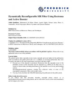
(1-D DCT) to the rows of the pixel matrix, followed by 1-D DCT on the results along the columns. For high throughput, the eight row (column) 1-D DCTs can be computed in parallel. A fast 1-D DCT algorithm [3] operating on an 8-pixel block involves 26 additions and 16 multiplications. When mapping 2-DCT upon an 8 × 8 pixel matrix to MorphoSys, each pixel is mapped to a RC. Coefficients needed for the computation are provided as constants in the context words. To perform eight 1-D DCTs along the rows of the pixel matrix, context is broadcast along the columns of the RC Array. Once the row 1-D DCTs are complete, the next step is to compute 1-D DCTs along the columns. Now, context is broadcast along the rows of the RC Array. As MorphoSys has the ability to broadcast context along both rows and columns of the RC Array, the need of transposing the pixel matrix is eliminated. This is a key aspect to achieve high performance in this application. The operand data bus is wide enough to load eight pixels at a time. Therefore, the entire pixel matrix can be loaded in eight cycles. Once data is in the RC Array, two butterfly operations are performed to compute intermediate variables. Inter-quadrant connectivity provided by the express lanes enables one butterfly operation in three cycles. As the butterfly operations are also performed in parallel, only six cycles are necessary to accomplish the butterfly operations for the whole matrix. The following number of cycles is necessary for a 2-D DCT: 8 cycles are needed for data load; both row and column 1-D DCTs take 12 cycles; 6 cycles are necessary for the butterfly operations; 3 additional cycles are used for data re-arrangement; and 8 cycles are needed for result write back. In the total, MorphoSys requires 37 cycles to complete 2-D DCT on an 8 × 8 pixel matrix. Figure 9 shows the relative performance figures for 2-D DCT on MorphoSys and other systems. PENTIUM MMX is a software implementation written in optimized Pentium assembly code using 64-bit special MMX instructions [4]. REMARC [5] is another reconfigurable system, but specifically targeted to multimedia applications. V830R/AV [6] is a superscalar multimedia processor. TMS320C80 [7] is a commercial digital signal processor. Observe that execution of DCT/IDCT on MorphoSys results in a six times speedup as compared to a Pentium MMXbased system. For the DCT algorithm, MorphoSys yields a throughput better than that achieved by specific hardware designs.
Figure 9. Performance Comparison for DCT/IDCT
4.2 Motion Estimation Motion estimation is widely used in video compression to identify redundancy between frames. The most popular technique for motion estimation is the block-matching algorithm, due to its simple hardware implementation. Among the different block-matching methods, Full Search Block Matching (FSBM) involves the maximum computations. However, FSBM gives an optimal solution with low control overhead. Typically, FSBM is formulated using the mean absolute difference (MAD) criterion as follows: MAD(m, n)= given
N
N
i =1
j =1
∑ ∑ R(i, j) − S(i + m, j + n)
p ≤ m, n ≤ q
where: p and q are the maximum displacements; R(i,j) is the reference block of size N × N pixels at coordinates (i, j); and S(i+m, j+n) is the candidate block within a search area of size (N+p+q)2 pixels in the previous frame. The displacement vector is represented by (m, n), and the motion vector is determined by the least MAD(m, n) among all the (p+q+1)2 possible displacements within the search area. Figure 10 shows the RC Array configuration for FSBM motion estimation with N=16 and p=q=8. For each reference block, three consecutive candidate blocks are calculated simultaneously in the RC Array. As depicted in Figure 10, each RC in the first, fourth, and seventh rows performs the computation:
Pj = ∑ | R(i, j ) − S (i + m, j + n) | 1≤i≤16
7
S(i+m, j+n) R(i, j)
RC operations | R − S | & accumulate
The ASIC architectures have the same processing power (in terms of processing elements) as MorphoSys, though they employ customized hardware units such as parallel adders to enhance performance.
Partial sums accumulate Partial sums accumulate
4. Implementation of MorphoSys
Results to Tiny RISC
| R − S| & accumulate Register (delay element) Register (delay element) | R − S | & accumulate Partial sums accumulate
Figure 10: RC Array Configuration for Motion Estimation.
where Pj is the partial sum. The eight partial sums (Pj) generated in these rows are then passed to the second, third, and eighth rows respectively to perform the computation:
MAD
(m , n ) =
∑
1 ≤ j ≤ 16
P
j
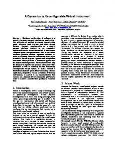
Subsequently, three MAD values corresponding to three candidate blocks are sent to TinyRISC for comparison. After TinyRISC updates the motion vector, the RC array starts block matching for the next three candidate blocks. Based on the computation model shown above, it takes 36 clock cycles to finish the matching with three candidate blocks. There are (8+8+1)2 = 289 candidate blocks in each search area, and simulation results show that a total of 4989 cycles are required to finish the matching of the whole search area and update and motion vector. MorphoSys performance is here compared with two ASIC architectures described in [8] and [9] for matching one 8×8 reference block against its search area of 8 pixels displacement. The result is shown in Figure 11. Cycles 1200 1000 800 600 400 200 0 ASIC[8]
ASIC[9]
MorphoSys
Figure 11: Performance Comparison for Motion Estimation
MorphoSys is tightly-coupled reconfigurable system. The TinyRISC core processor, the RC Array and the other components are integrated into a single chip. The first implementation of MorphoSys is called the M1 chip. M1 is being designed for operation at 100 MHz clock frequency, using a 0.35 µm CMOS technology. The TinyRISC core processor and the DMA controller were modeled using VHDL, and CAD tools were used to perform RTL/layout synthesis from the structural description. The other components were completely custom designed (TinyRISC's data register file and data cache core were also custom designed). The final design was obtained through the integration of both synthesized and custom parts. Table I shows the transistor count for each M1 component. Table I. Transistor count for the M1 chip Component TinyRISC RC Array Context Memory Frame Buffer DMA Controller SRAM Controller Total
Transistors 96,038 1,195,392 105,096 139,106 20,594 1,180 1,557,406
The complete design methodology includes two fundamental procedures: standard cell approach and custom design approach. For the standard cell blocks, the EDIF netlist is generated from VHDL using Synopsys Design Compiler. Then, Mentor Graphics AutoCells is used to generate the layout. The layouts of custom blocks are designed using Magic 6.5. Routing of symmetrical RC Array is done manually using L language. By taking both layouts from AutoCells and Magic, Mentor Graphics MicroPlan and MicroRoute are employed to handle the integration of the individual components. The final layout is illustrated in Figure 12 (uncompacted, no pad ring). Its dimension is 14.5mm by 12.5mm. Post-layout simulation involves three steps. First, test vectors and test results are generated from VHDL. Second, the final layout is extracted and simulated using Lsim. Finally, the above two results are compared.
8
A software development environment for the M1 chip is already available. It comprises: a SUIF-based C compiler for the TinyRISC core processor; an assembler-like parser for context generation; and a GUI tool, called mView, which supports interactive programming and simulation. Using mView, the programmer can specify the functions and the interconnections corresponding to each context for the application. mView then automatically generates the appropriate context file. As a simulation tool, mView reads a context file and displays the RC outputs and interconnection patterns at each cycle of the application execution. The M1 chip is designed to operate on a standard PCI-based board. Through the PCI interface, the host system downloads code and data into the on-board MorphoSys' main memory, and uploads processed data. The design of the M1 board is currently under development. The next implementation of MorphoSys (the M2 chip) will be designed to be an independent system. In this case, the TinyRISC core processor will also perform as an I/O processor.
5. Conclusions This paper introduced the MorphoSys reconfigurable system. Among its important features, we emphasize the powerful configurable elements and the rich, flexible interconnection network. The internal configuration memory allows for multiple resident contexts and dynamic, low latency reconfigurability. An internal data memory and DMA controller allow for high speed data transfers. The performance figures here presented demonstrate the potential of the MorphoSys architecture. For the DCT algorithm, MorphoSys is significantly faster than a software implementation running on high-performance, superscalar general-purpose microprocessors. Moreover, MorphoSys delivers a performance close or better to that provided by some ASICs. In addition to DCT and Motion Estimation, we have also mapped other important applications, e.g., Automatic Target Recognition (ATR) and some encryption algorithms (IDEA, 3-way). MorphoSys behaves similarly for these other applications, exhibiting performance significantly superior to implementations on general-purpose processors and comparable to ASIC implementations. Due to its characteristics, we believe that MorphoSys will have a major impact on adaptive and high-performance computing, addressing the requirements of both current and future applications.
Figure 12. Layout of the M1 chip.
Acknowledgments This research is funded by the Defense and Advanced Research Projects Agency (DARPA) of the Department of Defense under Contract Number F-33615-97-C-1126.
References [1] W. H. Mangione-Smith et al., “Seeking Solutions in Configurable Computing”, IEEE Computer, Dec. 1997, pp. 38-43. [2] S. Brown, J. Rose, “Architecture of FPGAs and CPLDs: A Tutorial”, IEEE Design and Test of Computers, Vol. 13, No. 2, 1996, pp.52-57. [3] W-H Chen, C. H. Smith and S. C. Fralick, “A Fast Computational Algorithm for the Discrete Cosine Transform,” IEEE Trans. on Comm., Vol. COM-25, No. 9, September 1977, pp. 1004-1009. [4] Application Notes for Pentium MMX, found at URL http://developer.intel.com/drg/mmx/appnotes. [5] T. Miyamori, K. Olukotun, “A Quantitative Analysis of Reconfigurable Coprocessors for Multimedia Applications”, Procedings of the IEEE Symposium on Field Programmable Custom Computing Machines, 1998. [6] T. Arai et al., V830R/AV: “Embedded Multimedia Superscalar RISC Processor”, IEEE Micro, Mar./Apr. 1998, pp. 36-47.
9
[7] F. Bonimini et al., “Implementing an MPEG2 Video Decoder Based on TMS320C80 MVP”, SPRA 332, Texas Instruments, Sept. 1996. [8] C. Hsieh, T. Lin, “VLSI Architecture For Block Matching Motion Estimation Algorithm”, IEEE Transaction on CSVT, Vol. 2, June, 1992. [9] K-M Yang, M-T Sun, and L.Wu, “A Family of VLSI Designs for Motion Compensation Block Matching Algorithm”, IEEE Transaction on Circuits and Systems. Vol. 36. No.10, Oct 1989.
10